Note : Les descriptions sont présentées dans la langue officielle dans laquelle elles ont été soumises.
W096/02120 58~ PCTJUS95J08275
S P E C I F I C A T I O N
HEARINf~ .AID DEVICE INCORPORATING
SIGNAh PROCESSING TECHNIQUES
Background of the Invention
!. Field of the Invention
The present invention relates to electronic hearing aid devices for use by the
hearing
impaired and to methods for providing hearing compensation. More particularly,
the present
invention relates to such devices and methods utilizing both analog and
digital signal process-
ing techniques.
2. -The Prior Art
One of the most common complaints of hearing aid users is the inability to
hear in the
presence of noise. As a result, several researchers have opted for acoustic
schemes which
suppress noise to enhance the intelligibility of sound. Examples of this
approach are found in
United States Patents 4,025,721 to Graupe, 4,405,831 to Michaelson, 4,185,168
to Graupe et
al., 4,188,667 to Graupe et al., 4,025,721 to Graupe et al., 4,135,590 to
Gaulder, and
4,759,071 to Heide et al.
1
SUBSTITUTE SHEET (RULE 26)
wo s6iozta° 2 ~ 9 4 5 8 3 P~T~S95~a8275
Other approaches have focussed upon feedback suppression and equalization
(ilnited
States Patents 4,602,337 to Cox, and 5,016,280 to Engebretson), dual
microphone co~gura-
tions (United States Patents 4,622,440 to Slavin and 3,927,279 to Nakamura et
al.), or upon
coupling to the ear in unusual ways (e.g., R',F links, electrical stimulation,
etc.) to improve in-
telligibility. Examples of these approaches. are found in United States
Patents 4,545,082 to
Engebretson, 4,052,572 to Shafer, 4,852,177 to Ambrose, and 4,731,850 to
Levitt.
Still other approaches have opted for digital programming control
implementations
which will accommodate a multitude of compression and filtering schemes.
Examples of such
approaches are found in United States Patents 4,471,171 to Kopke et al. and
5,027,410 to
Williamson. Some approaches, such as that disclosed in United States Patent
5,083,312 to
Newton, utilize heating aid structures wluch allow flexibility by accepting
control signals re-
ceived remotely by the aid.
United States Patent 4,187,413 to lbioser discloses an approach for a digital
hearing
aid which uses an analog-to-digital converter, a digital-to-analog converter,
and implements a
fixed transfer function H(z). However, a review of neuro-psychological models
in the litera-
tore and numerous measurements resulting in Steven's and Fechner's laws (see
S. S. Stevens,
Psychophysics, Wiley 1975; G. T. Fechner, Elemente der Psychophysik, Breitkopf
u. H~rtel,
Leipzig, 1860) conclusively reveal that the response of the ear to input sound
is nonlinear.
Hehce, no fixed transfer function H(z) exists which will fully compensate for
hearing.
United States Patent 4,425,481 to ll~langold, et. al. discloses a programmable
digital
signal processing (DSP) device with features similar or identical to those
commercially avail-
2
SUBSTITUTE SHEET (RULE 26)
WO 96102120 219 4 5 8 3 PCT~895108275
able, but with added digital control in the implementation of a three-band
(lowpass, bandpass,
and highpass) hearing aid. The outputs of the three frequency bands are each
subjected to a
digitally-controlled variable attenuator, a limiter, and a final stage of
digitally-controlled at-
tenuation before being summed to provide an output. Control of attenuation is
apparently so-
complished by switching in response to different acoustic environments.
United States Patents 4,366,349 and 4,419,544 to Adelman describe and trace
the
processing of the human auditory system, but do not reflect an understanding
of the role of the
outer hair cells within the ear as a muscle to amplify the incoming sound and
provide increased
basilar membrane displacement. These references assume that hearing
deterioration makes it
desirable to shift the frequencies and amplitude of the input stimulus,
thereby transferring the
location of the auditory response from a degraded portion of the ear to
another area within the
ear (on the basilar membrane) which has adequate response.
Mead C. Killion, The k-amp hearing aid. an attempt to present high frdelity
for per-
sons with impaired hearing, American Journal of Audiology, 2(2): pp. 52-74,
July 1993,
states that based upon the results of subjective listening tests for acoustic
data processed with
both linear gain and compression, either approach performs equally well. It is
argued that the
important factor in restoring hearing for individuals with losses is to
provide the appropriate
gain. Lacking a mathematically modeled analysis of that gain, several
compression techniques
have been proposed, e.g., United States Patent 4,887,299 to Cummins; United
States Patent
3,920,931 to Yanick, Jr.; United States Patent 4,118,604 to Yanick, Jr.;
United States Patent
4,052,571 to Gregory; United States Patent 4,099,035 to Yanick, Jr. and United
States Patent
5,278,912 to Waldhauer. Some involve a linear fixed high gain at soft input
sound levels and
switch to a lower gain at moderate or loud sound levels. Others propose a
linear gain at the
3
SUBSTITUTE SHEET (RULE 26)
wo 9siozaao 2 1 ~ ~ 5 8 3 rcart~s9s~osz~s
soR sound intensities, a changing gain or compression at moderate intensities
and a reduced,
fixed linear gain at high or loud intensities. Still others propose table look-
up systems with no
details specified concerning formation of look-up tables, and others allow
programmable gain
without specification as to the operating parameters.
Switching between the gain mechanisms in each of these sound intensity regions
has
introduced significant distracting artifacts a.nd distortion in the sound.
Further, these gain-
switched schemes have been applied typically in hearing aids to sound that is
processed in two
or three frequency bands, or in a single frequency band with pre-emphasis
filtering.
Insight into the difficulty with prior art gain-switched schemes may be
obtained by ex-
amining the human auditory system. For each frequency band where hearing has
deviated
from the normal threshold, a different sound compression is required to
provide for normal
hearing sensation to result. The application of gain schemes which attempt to
combine more
than a critical band (i.e., resolution band in hearing as defined in Jack Katz
(Ed.) Handbook of
Clinical Audiolog~, WilIiams & Wilkins, Baltimore, third ed., 1985) in
frequency range cannot
produce the appropriate hearing sensation in the listener. If, for example, it
is desired to com-
bine two frequency bands then some conditions must be met in order for the
combination to
correctly compensate for the hearing loss. These conditions for the frequency
bands to be
combined are that they have the same normal hearing threshold and dynamic
range and require
the same corrective hearing gain. In general, this does not occur even if a
hearing loss is con-
scant in amplitude across several critical bands of hearing. Failure to
properly account for the
adaptive full-range compression will result in degraded hearing or
equivalently, loss of fidelity
and intelligibility by the hearing impaired listener. Therefore, prior art
which does not provide
4
SUBSTITUTE SHEET (RULE 26)
w096/02120 219 4 5 8 3 p~~S95108275
sufficient numbers of frequency bands to compensate for hearing losses will
produce degraded
hearing.
Several schemes have been proposed which use multiple bandpass filters
followed by
compression devices (see United States Patents 4,396,806 to Anderson,
3,784,750 to Stearns
et al., and 3,989,904 to Rohrer).
One example of prior art in United States Patent No.-5,029,Z1Tto Chabries
focussed
on an FFT frequency domain version of a human auditory model. The FFT
implements an ef
ficiently-calculated frequency domain filter which uses fixed filter bands in
place of the critical
band equivalents which naturally occur in the ear due to its unique geometry,
thereby requiring
that the frequency resolution of the FFT be equivalent to the smallest
critical band to be com-
pensated. The efficiency of the FFT is in large part negated by the fact that
many additional
filter bands are required in the FFT approach to cover the same frequency
spectrum as a dif
ferent implementation with critical bandwidth filters. This FFT implementation
is complex and
likely not suitable for low-power battery applications.
The prior-art FFT implementation introduces a block delay into the processing
system
inherent in the FFT itself. Blocks of samples are gathered for insertion into
the FFT. This
block delay introduces a time delay into the sound stream which is annoying
and can induce
stuttering when one tries to speak or can introduce a delay which sounds like
an echo when
low levels of compensation are required for the hearing impaired individual.
The prior art FFT implementation of a frequency-domain mapping between
perceived
sound and input sound levels for the normal and hearing impaired is undefined
phenome-
5
SUBSTITUTE SHEET (RULE 26)
WO 96102120 219 4 5 8 3 PCTIUS95108275 '
nalogically. In other words, lacking a description of the perceived sound
level versus input
sound level for both the desired hearing response and the hearing impaired
hearing response,
these values were left to be measured.
For acoustic input levels below hewing (i.e. soft background sounds which are
ever
present), the FFT implementation described above provides excessive gain. This
results in ar-
tifacts which add noise to the output signal. At hearing compensation levels
greater than 60
dB, the processed background noise level cwr become comparable to the desired
signal level in
intensity thereby introducing distortion and reducing sound intelligibility.
As noted above, the hearing aid literature has proposed numerous solutions to
the
problem of hewing compensation for the hewing impaired. While the component
parts that
are required to assemble a high ftdelity, full-range, adaptive compression
system have been
known since 1968, no one has to date proposed the application of the
multiplicative AGC to
the several bands of hearing to compensate for hearing losses. According to
the present in-
vention, this is precisely the operation required to provide near normal
hearing perception to
the hearing impaired.
Brief Description of the Invention
According to the present invention, a hearing compensation system for the
hearing im-
paired comprises an input transducer for converting acoustical information at
an input to
electrical signals at an output, an output trw~sducer for converting
electrical signals at an input
to acoustical information at an output, a plurality of bandpass filters, each
bandpass ftlter hav-
ing an input connected to the output of said input transducer, a plurality of
AGC circuits, each
6
SUBSTITUTE SHEET (RULE 26)
CA 02194583 1999-10-20
individual AGC circuit associated with a different one of the
bandpass filters and having an input connected to the output
of its associated bandpass filter and an output connected to
the input of the output transducer. A presently preferred
embodiment of the: invention employs 12-15 1/3 octave bandpass
filters and operates over a bandwidth of between about 200-
10,000 Hz. In the presently preferred embodiment, the AGC
circuits are mult.iplicative AGC circuits. The filters are
designed as 1/3 octave multiples in bandwidth over the band
from 500 Hz to 10,000 Hz, with a single band filter from
0-500 Hz.
In accordance with the present invention, there is
provided a hearing compensation system comprising: an input
transducer for converting acoustical information at an input
thereof to electrical signals at an output thereof; an output
transducer for converting electrical signals at an input
thereof to acoustical information at an output thereof; a
plurality of banclpass filters, each bandpass filter having an
input connected t.o said output of said input transducer; a
plurality of mult,iplicative AGC circuits, each individual
multiplicative AGC circuit associated with a different one of
said bandpass filters and having an input connected to the
output of its as~;ociated bandpass filter and an output summed
with the outputs of all other ones of said multiplicative AGC
7
CA 02194583 1999-10-20
circuits to form a summed output, said summed output
connected to the input of said output transducer; wherein
each of said mult:iplicative AGC circuits comprises: a first
amplifier element: having an input and an output, said first
amplifier element: having a gain of 1/emax, where emax is the
maximum value of an audio envelope to be presented to said
AGC circuit for which AGC amplification is to result; a
logarithmic element having an input connected to said output
of said first amplifier element, said logarithmic element
having a first output carrying a signal indicating the sign
of a signal at said input and a second output carrying a
signal proportional to the logarithm of the absolute value of
said signal at said input; a filter having an input connected
to said second output of said logarithmic element and an
output, said filter having a throughput delay; a delay
element having an input. connected to said first output of
said logarithmic element and an output, said delay element
having a delay equal to said throughput delay; an exponential
element having a first input connected to said first output
of said logarithmic element, a second input connected to said
second output of said logarithmic element, and an output; and
a second amplifier element having an input and an output,
said input connected to said output of said exponential
element, said second amplifier having a gain of emax~
7a
CA 02194583 1999-10-20
In accordance with the present invention, there is
further provided a hearing compensation system comprising:
an input transducer for- converting acoustical information at
an input thereof to electrical signals at an output thereof;
an output transducer far converting electrical signals at an
input thereof to acoustical information at an output thereof;
a plurality of ba.ndpass filters, each bandpass filter having
an input connected to said output of said input transducer; a
plurality of multiplicative AGC circuits, each individual
multiplicative AGC circuit associated with a different one of
said bandpass filters and having an input connected to the
output of its associated bandpass filter and an output summed
with the outputs of all other ones of said multiplicative AGC
circuits to form a summed output, said summed output
connected to the input of said output transducer; wherein
each of said multiplicative AGC circuits comprises: a first
amplifier element having an input and an output, said input
connected to an input node of its AGC circuit, said first
amplifier element having a gain of 1/e emax~ where emax is
the maximum value of an audio envelope to be presented to
said AGC circuit for which AGC amplification is to result; an
envelope detector element having an input connected to said
output of said first amplifier element and an output; a
logarithmic element having an input connected to said output
of said envelope detector element, said logarithmic element
having an output carrying a signal proportional to the
7b
CA 02194583 1999-10-20
logarithm of the value of said signal at said input; a second
amplifier element: having an input and an output, said input
connected to sari output of said logarithmic element, said
second amplifier having a gain of k-1 where k is a number
between zero and one; an exponential element having an input
and an output, said input connected to said output of said
second amplifier element; and a multiplier element having a
first input connE;cted to said output of said exponential
element, a second input connected to said input node, and an
output connected to an output node of its AGC circuit.
In accordance with the present invention, there is
further provided a hearing compensation system comprising:
an input transducer for converting acoustical information at
an input thereof to electrical signals at an output thereof;
an output transducer for converting electrical signals at an
input thereof to acoustical information at an output thereof;
a plurality of bandpass filters, each bandpass filter having
an input connected to said output of said input transducer; a
plurality of mult:iplicative AGC circuits, each individual
multiplicative AGC circuit associated with a different one of
said bandpass filters and having an input connected to the
output of its as~;ociated bandpass filter and an output summed
with the outputs of all other ones of said multiplicative AGC
circuits to form a summed output, said summed output
connected to the input of said output transducer; wherein
7c
CA 02194583 1999-10-20
each of said mult:iplicative AGC circuits comprises: an
envelope detector element having an input and an output, said
input connected t:o an input node of its AGC circuit; a first
amplifier element: having an input and an output, said input
connected to said output of said envelope detector element,
said first amplifier element having a gain of 1/emax where
emax is the maximum value of an audio envelope to be
presented to saicL AGC circuit for which AGC amplification is
to result; a logarithmic element having an input connected to
said output of said first amplifier element, said logarithmic
element having an output carrying a signal proportional to
the logarithm of the value of said signal at said input; a
second amplifier element having an input and an output, said
input connected t.o said output of said logarithmic element,
said second amplifier having a gain of k-1 where k is a
number between zero and one; an exponential element having an
input and an output, said input connected to said output of
said second amplifier element; a soft limiter element having
an input connected to said output of said second amplifier
element and an output, said soft limiter element having a
limiter characteristic selected such that its gain is limited
to a maximum value equal to the gain required to compensate
for an individual.'s hearing loss at threshold in a frequency
band passed by tree one of said bandpass filters with which
its AGC circuit i.s associated; and a multiplier element
having a first input connected to said output of said soft
7d
CA 02194583 1999-10-20
limiter element, a second input connected to said input node,
and an output connected to an output node of its AGC circuit.
In accordance with the present invention, there is
further provided a sound discriminator system comprising: an
input transducer for converting acoustical information at an
input thereof to electrical signals at an output thereof; an
output transducer for converting electrical signals at an
input thereof to acoustical information at an output thereof;
l0 a plurality of bandpass filters, each bandpass filter having
an input connected to said output of said input transducer;
a plurality of multipl:icative AGC circuits, each individual
multiplicative ACC circuit associated with a different one of
said bandpass filters and having an input connected to the
output of its associated bandpass filter and an output summed
with the outputs of al:L other ones of said multiplicative AGC
circuits to form a summed output, said summed output
connected to the input of said output transducer, each
multiplicative AGC circuit comprising a first amplifier
element having an input and an output, said input connected
to an input node of its multiplicative AGC circuit, said
first amplifier element having a gain of 1/emax~ where emax
is the maximum value of an audio envelope to be presented to
said AGC circuit for which AGC amplification is to result, an
envelope detector: element having an input connected to said
output of said f~.rst amplifier element and an output, a
7e
CA 02194583 1999-10-20
logarithmic element having an input connected to said output
of said envelope detector element, said logarithmic element
having an output carrying a signal proportional to the
logarithm of the value of said signal at said input, a second
amplifier elemeni~ having an input and an output, said input
connected to said output of said logarithmic element, said
second amplifier having a gain of k-1 where k is a number
greater than one, an exponential element having an input and
an output, said :input connected to said output of said second
amplifier elemeni~, and a multiplier element having a first
input connected i~o said output of said exponential element, a
second input connected to said input node, and an output
connected to an output node of its multiplicative AGC
circuit.
In accordance with the present invention, there is
further provided a sound discriminator system comprising: an
input transducer for converting acoustical information at an
input thereof to electrical signals at an output thereof; an
output transducer for converting electrical signals at an
input thereof to acoustical information at an output thereof;
a plurality of bandpass filters, each bandpass filter having
an input connected to said output of said input transducer; a
plurality of muli~iplicative AGC circuits, each individual
multiplicative A~sC circuit associated with a different one of
said bandpass fi:Lters and having an input connected to the
7f
CA 02194583 1999-10-20
output of its associated bandpass filter and an output summed
with the outputs of all other ones of said multiplicative AGC
circuits to form a summed output, said summed output
connected to the input of said output transducer, each
multiplicative AGC circuit comprising an envelope detector
element having an input and an output, said input connected
to an input node of its multiplicative AGC circuit, a first
amplifier element having an input and an output, said input
connected to said output of said envelope detector element,
said first amplifier element having a gain of 1/emax, where
emax is the maximum value of an audio envelope to be
presented to said multiplicative AGC circuit for which AGC
amplification is to result, a logarithmic element having an
input connected to said output of said first amplifier
element, said logarithmic element having an output carrying a
signal proportional to the logarithm of the value of said
signal at said output, a second amplifier element having an
input and an output, said input connected to said output of
said logarithmic element, said second amplifier having a gain
of k-1 where k is a number greater than one, an exponential
element having a:n input and an output, said input connected
to said output of said. second amplifier element, a soft
limiter element :having an input connected to said output of
said second amplifier element and an output, said soft
limiter element :having a limiter characteristic selected such
that its gain is limited to a maximum value equal to a
7g
CA 02194583 1999-10-20
preselected comfort level in a frequency band passed by the
one of said band;pass filters with which its multiplicative
AGC circuit is associated, and a multiplier element having a
first input connected to said output of said soft limiter
element, a second input connected to said input node, and an
output connected to an output node of its multiplicative AGC
circuit.
In accordance with the present invention, there is
further provided a sound discriminator system comprising: an
input transducer for converting acoustical information at an
input thereof to electrical signals at an output thereof; an
output transducer for converting electrical signals at an
input thereof to acoustical information at an output thereof;
a plurality of bandpass filters, each bandpass filter having
an input connected to said output of said input transducer; a
plurality of multiplicative AGC circuits, each individual
multiplicative AGC circuit associated with a different one of
said bandpass filters and having an input connected to the
output of its associated bandpass filter and an output summed
with the outputs of all other ones of said multiplicative AGC
circuits to form a summed output, said summed output
connected to the input of said output transducer, each
multiplicative AGC circuit comprising a first amplifier
element having an input and an output, said input connected
to an input node of its multiplicative AGC circuit, said
7h
CA 02194583 1999-10-20
first amplifier element having a gain of 1/emax, where emax
is the maximum value of an audio envelope to be presented to
said AGC circuit for which AGC amplification is to result, an
envelope detector element having an input connected to said
output of said first amplifier element and an output, a
logarithmic element having an input connected to said output
of said envelope detector element, said logarithmic element
having an output carrying a signal proportional to the
logarithm of the value of said signal at said input, a second
amplifier element having an input and an output, said input
connected to said output of said logarithmic element, said
second amplifier having a gain of k-1 where k is a number
between zero and -1, an exponential element having an input
and an output, said input connected to said output of said
second amplifier element, and a multiplier element having a
first input connected to said output of said exponential
element, a second input connected to said input node, and an
output node of its multiplicative AGC circuit.
In accordance with the present invention, there is
further provided a sound discriminator system comprising: an
input transducer for converting acoustical information at an
input thereof to electrical signals at an output thereof; an
output transducer for converting electrical signals at an
input thereof to acoustical information at an output thereof;
a plurality of bandpass filters, each bandpass filter having
7i
CA 02194583 1999-10-20
an input connected to said output of said input transducer; a
plurality of multiplicative AGC circuits, each individual
multiplicative AGC circuit associated with a different one of
said bandpass filters and having an input connected to the
output of its associated bandpass filter and an output summed
with the outputs of all other ones of said multiplicative AGC
circuits to form a summed output, said summed output
connected to the input of said output transducer, each
multiplicative AGC circuit comprising an envelope detector
element having an input and an output, said input connected
to an input node of its muliplicative AGC circuit, a first
amplifier element having an input and an output, said input
connected to said output of said envelope detector element,
said first amplifier element having a gain of 1/emax, where
emax is the maximum value of an audio envelope to be
presented to said multiplicative AGC circuit for which AGC
amplification is to result, a logarithmic element having an
input connected to said output of said first amplifier
element, said logarithmic element having an output carrying a
signal proportional to the logarithm of the value of said
signal at said input, a second amplifier element having an
input and an output, said input connected to said output of
said logarithmic element, said second amplifier having a gain
of k-1 where k is a number between zero and -1, an
exponential element having an input and an output, said input
connected to said output of said second amplifier element, a
7J
CA 02194583 1999-10-20
soft limiter element having an input connected to said output
of second amplifier element and an output, said soft limiter
element having a limiter characteristic selected to limit its
gain to a maximum value equal to a preselected comfort level
in a frequency band passed by the one of said bandpass
filters with which its multiplicative AGC circuit is
associated, and a multiplier element having a first input
connected to said output of said soft limiter element, a
second input connected to said input node, and an output
connected to an output node of its multiplicative AGC
circuit.
In accordance with the present invention, there is
further provided a hearing compensation system comprising:
an input transducer for converting acoustical information at
an input thereof to electrical signals at an output thereof;
an output transducer for converting electrical signals at an
input thereof to acoustical information at an output thereof;
a plurality of b~andpass filters, each bandpass filter having
an input connected to said output of said input transducer; a
plurality of AGC circuits, each individual AGC circuit
associated with a different one of said bandpass filters and
having an input ~~onnected to the output of its associated
bandpass filter .and an output summed with the outputs of all
other ones of said AGC circuits to form a summed output, said
summed output connected to the input of said output
7k
CA 02194583 1999-10-20
transducer, wherein each of said AGC circuits comprises a
first amplifier element having an input and an output, said
first amplifier element having a gain of 1/emax, where emax
is the maximum value of an audio envelope to be presented to
said AGC circuit for which AGC amplification is to result, a
logarithmic element having an input connected to said output
of said first amplifier element, said logarithmic element
having a first output carrying a signal indicating the sign
of a signal at said input and a second output carrying a
signal proportional to the logarithm of the absolute value of
said signal at said input, a filter having an input connected
to said second output of said logarithmic element and an
output, said filter having a throughput delay, a delay
element having a:n input connected to said first output of
said logarithmic element and an output, said delay element
having a delay e~xual to said throughput delay, an exponential
element having a first input connected to said output of said
delay element, a second input connected to said output of
said filter element, and an output, and a second amplifier
element having a:n input and an output, said input connected
to said output of said exponential element, said second
amplifier having a gain of emax~
In accordan~~e with the present invention, there is
further provided a hearing compensation system comprising:
an input transdu~~er for converting acoustical information at
71
CA 02194583 1999-10-20
an input thereof to electrical signals at an output thereof;
an output transducer for converting electrical signals at an
input thereof to acoustical information at an output thereof;
a plurality of bandpass filters, each bandpass filter having
an input connected to said output of said input transducer; a
plurality of multiplicative AGC circuits, each individual
multiplicative AGC circuit associated with a different one of
said bandpass filters and having an input connected to the
output of its associated bandpass filter and an output summed
with the outputs of all other ones of said multiplicative AGC
circuits to form a summed output, said summed output
connected to the input of said output transducer, wherein
each of said multiplicative AGC circuits comprises a first
amplifier element having an input and an output, said input
forming the input node of its multiplicative AGC circuit,
said first amplifier element having a gain of 1/emax, where
emax is the maximum value of an audio envelope to be
presented to said multiplicative AGC circuit for which AGC
amplification is to result, an envelope detector element
having an input connected to said output of said first
amplifier element, a cutoff frequency and an output, said
cutoff frequency being a monotonic function of the center
frequency of said bandpass filter associated with said
multiplicative AGC circuit, a logarithmic element having an
input connected to said output of said envelope detector
element, said logarithmic element having an output carrying a
7m
CA 02194583 1999-10-20
signal proportional to the logarithm of the value of said
signal at said input, a second amplifier element having an
input and an output, said input connected to said output of
said logarithmic element, said second amplifier having a gain
of k-1 where k is a number between zero and one, an
exponential element having an input and an output, said input
connected to said output of said second amplifier element,
and a multiplier element having a first input connected to
said output of said exponential element, a second input
connected to said input node of said multiplicative AGC
circuit, and an output forming the output node of its
multiplicative AGC circuit.
In accordance with the present invention, there is
further provided a hearing compensation system comprising:
an input transducer for converting acoustical information at
an input thereof to electrical signals at an output thereof;
an output transducer for converting electrical signals at an
input thereof to acoustical information at an output thereof;
a plurality of bandpass filters, each bandpass filter having
an input connected to said output of said input transducer; a
plurality of multiplicative AGC circuits, each individual
multiplicative A~GC circuit associated with a different one of
said bandpass filters and having an input connected to the
output of its associated bandpass filter and an output summed
with the outputs of all other ones of said multiplicative AGC
7n
CA 02194583 1999-10-20
circuits to form a summed output, said summed output
connected to the input of said output transducer, wherein
each of said multiplicative AGC circuits comprises an
envelope detector element having an input connected to said
output of said first amplifier element, a cutoff frequency
and an output, said cutoff frequency being a monotonic
function of the center frequency of said bandpass filter
associated with ;said multiplicative AGC circuit, a first
amplifier element having an input and an output, said input
connected to said output of said envelope detector element,
said first amplifier element having a gain of 1/emax, where
emax is the maximum value of an audio envelope to be
presented to said multiplicative AGC circuit for which AGC
amplification is to result, a logarithmic element having an
input connected to said output of said first amplifier
element, said logarithmic element having an output carrying a
signal proportional to the logarithm of the value of said
signal at said input, a second amplifier element having an
input and an output, said input connected to said output of
said logarithmic element, said second amplifier having a gain
of k-1 where k i;s a number between zero and one, an
exponential element having an input and an output, said input
connected to said output of said second amplifier element, a
soft limiter elennent having an input connected to said output
of said second amplifier element and an output, said soft
limiter element lhaving a limiter characteristic selected such
CA 02194583 1999-10-20
that its gain is limited to a maximum value equal to the gain
required to compensate for an individual's hearing loss at
threshold in a frequency band passed by the one of said
bandpass filters with which its multiplicative AGC circuit is
associated, and a multiplier element having a first input
connected to said output of said soft limiter element, a
second input connected to said input node of said
muliplicative AGC circuit, and an output forming the output
node of its mult:iplicative AGC circuit.
In accordance with the present invention, there is
further provided a sound discriminator system comprising: an
input transducer for converting acoustical information at an
input thereof to electrical signals at an output thereof; an
output transducer for converting electrical signals at an
input thereof to acoustical information at an output thereof;
a plurality of bandpass filters, each bandpass filter having
an input connectE_d to said output of said input transducer
and an output; a plurality of multiplicative AGC circuits,
each individual rnultiplicative AGC circuit associated with a
different one of said bandpass filters and having an input
connected to the output of its associated bandpass filter and
an output summed with the outputs of all other ones of said
multiplicative AGC circuits to form a summed output, said
summed output connected to the input of said output
transducer, each multiplicative AGC circuit comprising a
7P
CA 02194583 1999-10-20
first amplifier element having an input and an output, said
input forming the input node of its multiplicative AGC
circuit, said first amplifier element having a gain of
1/emax, where emax is the maximum value of an audio envelope
to be presented to said AGC circuit for which AGC
amplification is to result, an envelope detector element
having an input connected to said output of said first
amplifier element, a cutoff frequency, said cutoff frequency
being a monotonic function of the center frequency of said
bandpass filter associated with said AGC circuit, and an
output, a logarithmic element having an input connected to
said output of said envelope detector element, said
logarithmic element having an output carrying a signal
proportional to the logarithm of the value of said signal at
said input, a second amplifier element having an input and an
output, said input connected to said output of said
logarithmic element, said second amplifier having a gain of
k-1 where k is a number greater than one, an exponential
element having an input and an output, said input connected
to said output of said second amplifier element, and a
multiplier element having a first input connected to said
output of said exponential element, a second input connected
to said input node of said multiplicative AGC circuit, and an
output forming the output node of its multiplicative AGC
circuit.
7q
CA 02194583 1999-10-20
In accordance with the present invention, there is
further provided a sound discriminator system comprising: an
input transducer for converting acoustical information at an
input thereof to electrical signals at an output thereof; an
output transducer for converting electrical signals at an
input thereof to acoustical information at an output thereof;
a plurality of bandpass filters, each bandpass filter having
an input connected to said output of said input transducer;
a plurality of multiplicative AGC circuits, each individual
multiplicative AGC circuit associated with a different one of
said bandpass filters and having an input connected to the
output of its associated bandpass filter and an output summed
with the outputs of all other ones of said multiplicative AGC
circuits to form a summed output, said summed output
connected to the input of said output transducer, each
multiplicative AGC circuit comprising an envelope detector
element having a:n input connected to said output of said
first amplifier element, a cutoff frequency and an output,
said cutoff frequency being a monotonic function of the
center frequency of said bandpass filter associated with said
multiplicative AGC circuit, a first amplifier element having
an input and an output, said input connected to said output
of said envelope detector element, said first amplifier
element having a gain of 1/emax, where emax is the maximum
value of an audio envelope to be presented to said
multiplicative AGC circuit for which AGC amplification is to
7r
CA 02194583 1999-10-20
result, a logarithmic element having an input connected to
said output of said first amplifier element, said logarithmic
element having an output carrying a signal proportional to
the logarithm of the value of said signal at said input, a
second amplifier element having an input and an output, said
input connected to said output of said logarithmic element,
said second amplifier having a gain of k-1 where k is a
number greater than one, an exponential element having an
input and an output, said input connected to said output of
l0 said second amplifier element, a soft limiter element having
an input connected to said output of said second amplifier
element and an output, said soft limiter element having a
limiter characteristic' selected such that its gain is limited
to a maximum value equal to a preselected comfort level in a
frequency band passed by the one of said bandpass filters
with which its multiplicative AGC circuit is associated, and
a multiplier element having a first input connected to said
output of said soft limiter element, a second input connected
to said input node of said multiplicative AGC circuit, and an
output forming the output node of its multiplicative AGC
circuit.
7s
CA 02194583 1999-10-20
Brief Description of the Drawing Figures
FIG. 1 is a block diagram of a presently preferred
hearing compensation system according to the present
invention.
FIG. 2 is a more detailed block diagram of a typical
multiplicative AGC circuit according to a presently preferred
embodiment of the invention.
FIG. 3 is a plot of the response characteristics of the
filter employed in the multiplicative AGC circuit of FIG. 2.
FIG. 4 is a block diagram of an alternate embodiment of
the multiplicative AGC circuit of the present invention
wherein the log function follows the low-pass filter
function.
FIG. 5 is a block. diagram of an alternate embodiment of
the multiplicatiwe AGC circuit of the present invention
further including a modified soft-limiter.
7t
WO 96102120 219 4 5 8 3 PCTIUS95108275
Detailed Description of A Preferred Embodiment
Those of ordinary skill in the art will realize that the following description
of the pres-
ent invention is illustrative only and not in any way limiting. Other
embodiments of the inven-
tion will readily suggest themselves to such skilled persons.
According to the present invention, it has been discovered that the
appropriate ap-
proach to high fidelity hearing compensation is to separate the input acoustic
stimulus into fre-
quency bands with a resolution at least equal to the critical bandwidth, which
for a large range
of the sound frequency spectrum is less than I/3 octave, and apply a
multiplicative AGC with
a fixed exponential gain coefficient for each band. Those of ordinary skill in
the art will rec-
ognize that the principles of the present invention may be applied to audio
applications other
than hearing compensation for the hearing innpaired. Non-exhaustive examples
of other appli-
cations of the present invention include music playback for environments with
high noise lev-
els, such as automotive environments, voice systems in factory environments,
and graphic
sound equalizers such as those used in stereophonic sound systems.
As will be appreciated by persons of ordinary skill in the art, the circuit
elements of the
hearing compensation apparatus of the present invention may be implemented as
either an
analog circuit or as a digital circuit, preferably a microprocessor or other
computing engine
performing digital signal processing (DSP) functions to emulate the analog
circuit functions of
the various components such as filters, amplifiers, etc. It is presently
contemplated that the
DSP version of the circuit is the preferred embodiment of the invention , but
persons of ordi-
nary skill in the art will recognize that an analog implementation, such as
might be integrated
8
SUBSTITUTE SHEET (RULE 26)
w0 96102120 219 4 5 8 3 PCT~S95J08275
on a single semiconductor substratex_will also fall within the scope of the
invention. Such
skilled persons will also realize that in a DSP implementation, the incoming
audio signal will
have to be time sampled and digitized using conventional analog to digital
conversion tech-
piques.
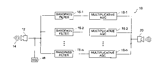
Referring first to FIG. 1, a block diagram of a presently preferred hearing
compensa-
Lion system 10 according to the present invention is presented. The hearing
compensation
system 10 according to a presently preferred embodiment of the invention
includes an input
transducer 12 for converting acoustical energy (shown schematically at
reference numeral 14)
into an electrical signal corresponding to that acoustical energy. Various
known hearing-aid
microphone transducers, such as a model EK 3024, available from Knowles
Electronics of Ith-
aca, Illinois, are available for use as input transducer 12, or other
microphone devices may be
employed.
The heart of hearing compensation system 10 of the present invention comprises
a plu-
ratify of audio bandpass filters. In FIG. 1, three audio bandpass filters are
shown at reference
numerals 16-1, 16-2 . . . 16-n to avoid overcomplicating the drawing.
According to a pres-
ently preferred embodiment of the invention , n will be an integer finm 12 to
15, although per-
sons of ordinary skill in the art will understand that the present invention
will function if n is a
different integer.
Audio bandpass filters 16-1 to 16-n preferably have a bandpass resolution of
I/3 oc-
tave or less, but in no case less than about 125 Hz, and have their center
frequencies loga-
rithniically spaced over a total audio spectrum of from about 200 Hz to about
10,000 Hz.
The audio bandpass filters may have bandwidths broader than 1/3 octave, i.e.,
up to an octave
9
SUBSTITUTE SHEET (RULE 26)
wo ssroziao 219 4 5 8 3 PCTIUS95/08275
or so, but with degrading performance. 'the design of 1/3 octave bandpass
filters is well
within the level of skill of the ordinary worker in the art. Therefore the
details of the circuit
design of any particular bandpass filter, whether implemented as an analog
filter or as a DSP
representation of an analog filter, will be simply a matter of design choice
for such skilled per
sons.
According to a presently preferred embodiment of the invention, bandpass
filters 16-I
through 16-n are realized as eighth-order Elliptic filters with about 0.5 dB
ripple in the pass-
band and about 70 dB rejection in the stopband. Those of ordinary skill in the
art will recog-
nine that several bandpass filter designs including, but not limited to, other
Elliptic, Butter-
worth, Chebyshev, or Bessel filters, may be employed. Further, filter banks
designed using
wavelets, as disclosed, for example, in R A. Gopinath Wavelets and Filter
Banks- New Re-
suits and Applications, PhD Dissertation, Rice University, Houston, Texas, May
1993, may
offer some advantage. Any ofthese bandpass filter designs may be employed
without deviat-
ing from the concepts of the invention disclosed herein.
Each individual bandpass filter 16-1 to 16-n is cascaded with a corresponding
multipli
cative automatic gain control (AGC) circuit. Three such devices 18-1, 18-2,
and 18-n are
shown in FIG. 1. Multiplicative AGC circuits are known in the art and an
exemplary configu
ration will be disclosed further herein.
The outputs of the multiplicative AGC circuits are summed together and are fed
to an
output transducer 20, which converts the electrical signals into acoustical
energy. As will be
appreciated by those of ordinary skill in the art, output transducer 20 may be
one of a variety
of known available hearing-aid earphone transducers, such as a model ED 1932,
available
SUBSTITUTE SHEET (RULE 26)
WO 96102120 219 4 5 8 3 p~NS95108275
firom Knowles Electronics of Ithaca, Illinois , in conjunction with a
calibrating amplifier to en-
sure the transduction of a specified electrical signal level into the
correspondingly specified
acoustical signal level. Alternately, transducer 20 may be another earphone-
like device or an
audio power amplifier and speaker system.
Referring now to FIG. 2, a more detailed conceptual block diagram of a typical
multi-
plicative AGC circuit 18 according to a presently preferred embodiment of the
invention is
shown. As previously noted, multiplicative AGC circuits are known in the art.
An illustrative
multiplicative AGC circuit which will function in the present invention is
disclosed in the arti-
cle T. Stockham, Jr., The Application of Generalized Linearity to Automatic
Gain Control,
IFF.R Transactions on Audio and Electroacoustics, AU-16(2): pp 267-270, June
1968. A
similar example of such a multiplicative AGC circuit may be found in United
States Patent No.
3,518,578 to Oppenheim et al.
Conceptually, the multiplicative AGC circuit which may be used in the present
inven-
tion accepts an input signal at amplifier 20 from the output of one of the
bandpass filters 16-n.
Amplifier 20 is set to have a gain of lle",~, where e,",~ is the maximum
allowable value of the
audio envelope for which AGC gain is applied (i.e., for input levels above
e",~ , AGC attenua-
tion results). Within each band segment in the apparatus of the present
invention, the quantity
e,~ is the maximum acoustic intensity for which gain is to be applied. This
gain level for e""x
(determined by audiological examination of a patient) often corresponds to the
upper comfort
level of sound. In an analog implementation of the present invention,
amplifier 20 may be a
known operational amplifier circuit, and in a DSP implementation, amplifier 20
may be a mul
tiplier function having the input signal as one input term and the constant
lle",~, as the other
input term.
11
SUBSTITUTE SHEET (RULE 26)
WO 96/02120 2 ,19 4 5 8 3 PCT/US95/08275
The output of amplifier 20 is processed in the "LOG" block 22 to derive the
logarithm
of the signal. The LOG block 22 derives a complex logarithm of the input
signal, with one
output representing the sign of the input signal and the other output
representing the logarithm
of the absolute value of the input. In an analog implementation of the present
invention, LOG
block 22 may be, for example, an amplifier having a logarithmic transfer
curve, or a circuit
such as the one shown in FIGS. 8 and 9 of United States Patent No. 3,518,578.
In a DSP im-
plementation, LOG block 22 may be implemented as a software subroutine running
on a mi-
croprocessor or similar computing engine as is well known in the art, or from
other equivalent
means such as a look-up table. Examples of such implementations are found in
Knuth, Don-
ald E., The Art of Computer Programnvng, Vol. 1, Fundamental Algorithms,
Addison-Wesley
Publishing 1968, pp. 21-26 and Abramowitz, M. and Stegun, LA., Handbook
ofMathematical
Functions, US Department of Commerce, National Bureau of Standards, Appl. Math
Series
55, 1968. Those of ordinary skill in the art will recognize that by setting
the gain of the am-
IS plifier 20 to I/e",~, the output of amplifier 20 (when the input is less
than e""x,) will never be
greater than one and the logarithm term out of LOG block 22 will always be 0
or less.
The first output of LOG block 22 containing the sign information of its input
signal is
presented to a Delay block 24, and a second output of LOG block 22
representing the loga-
rithm of the absolute value of the input signal is presented to a filter 26
having a characteristic
preferably like that shown in FIG. 3. Conceptually, filter 26 may comprise
both high-pass fil-
ter 28 and low-pass filter 30 followed by amplifier 32 having a gain equal to
K . As will be
appreciated by those of ordinary skill in the a.rt, high-pass filter 28 may be
synthesized by sub-
tracting the output of the low-pass filter from the input of the low-pass
filter.
12
SUBSTITUTE SHEET (RULE 26)
WO 96/02120 219 4 5 ~ 3 P~T~895108275
Both high-pass filter 28 and low-pass filter 30 have a cutoff frequency that
is deter-
mined by the specific application. In a hearing compensation system
application, a nominal
cutoff frequency is about 16 Hz, however, other cutoff frequencies may be
chosen for low-
pass filter 30 up to about 1/8 of the critical bandwidth associated with the
frequency band be-
ing processed without deviating from the concepts of this invention. Those of
ordinary skill
in the art will recognize that filters having response curves other than that
shown in FIG. 3
may be used in the present invention. For example, other non-voice
applications of the present
invention may require a cutoff frequency higher or lower than 16 Hz. As a
further example,
implementation of a cutoff frequency for low-pass filter 30 equal to 1/8 of
the critical band-
width associated with the frequency channel being processed (i.e., 16-1
through 16-n in FIG.
1) provides for more rapid adaptation to transient acoustic inputs such as a
gunshot, hammer
blow or automobile backfire.
The sign output of the LOG block 22 which feeds delay 24 has a value of either
1 or 0
and is used to keep track of the sign of the input signal to LOG block 22. The
delay 24 is such
that the sign of the input signal is fed to the EXP block 34 at the same time
as the data repre-
senting the absolute value of the magnitude of the input signal, resulting in
the proper sign at
the output. In the case of a digital embodiment of the present invention, the
delay will be null.
In the case of an analog embodiment, the delay is made equal to the delay of
the high-pass fil-
ter 28.
Those of ordinary skill in the art will recognize that many designs exist for
amplifiers
and for both passive and active analog filters as well as for DSP filter
implementations, and
that the design for the filters described herein may be elected from among
these available de-
13
SUBSTITUTE SHEET (RULE 26)
WO 9G/02t20 219 4 5 8 3 PCT/US95/08275
signs. For example, in an analog implementation of the present invention, high-
pass filter 28
and low-pass filter 30 may be conventional high-pass and low-pass filters of
known designs,
such as examples found in Van Valkenburg, M.E., Analog Filter Design, Holt,
Rinehart and
Winston, 1982, pp 58-59. Amplifier 32 may be a conventional operational
amplifier. In a
digital implementation of the present invention, amplifier 32 may be a
multiplier function hav-
ing the input signal as one input term and the constant K as the other input
term. DSP filter
techniques are well understood by those of ordinary skill in the art.
The outputs of high-pass filter 28 and amplifier 32 are combined and presented
to the
input of EXP block 34 along with the unmodified output of LOG block 22. EXP
block 34
processes the signal to provide an exponential fimction. In an analog
implementation of the
present invention, EXP block 34 may be an amplifier with an exponential
transfer curve. Ex-
amples of such circuits are found in FIGS. 8 and 9 of United States Patent No.
3,518,578. In
a DSP implementation EXP block 34 may be implemented as a software subroutine
as is well
known in the art, or from other equivalent means such as a look-up table.
Examples of
known implementations of this function are found in the ICnuth and Abramowitz
et al. refer-
ences, and United States Patent No. 3,518,578, previously cited.
Sound may be conceptualized as the product of two components. The first is the
al-
ways positive slowly varying envelope and may be written as e(t), and the
second is the rapidly
varying carrier which may be written as v(t). The total sound may be expressed
as:
s(t) _= e(t) ~ v(t)
14
SUBSTITUTE SHEET (RULE 26)
WO 96/02120 ~ ~ PCT/US95/08275
Since an audio waveform is not always, positive (i.e., v(t) is negative about
half of the
time), its logarithm at the output of LOG block 22 will have a real part and
an imaginary part.
If LOG block 22 is configured to process the absolute value of s(t) , its
output will be the sum
of log (e(t)le""~) and log w(t)~ . Since log w(t)~ contains high frequencies,
it will pass through
high-pass filter 28 essentially unaffected. The component log (e(i)/e,"~)
contains low fre-
quency components and will be passed by low-pass filter 30 and emerge from
amplifier 32 as
K log (e(t)le",~). The output of EXP block 34 will therefore be:
(e(t)lemax)K ~ v(t)
When K<l, it may be seen that the processing in the multiplicative AGC circuit
of FIG.
2 performs a compression function. Persons of ordinary skill in the art will
recognize that em-
bodiments of the present invention using these values of K are useful for
applications other
than hearing compensation.
According to a presently preferred embodiment of the invention employed as a
hearing
compensation system, K may be about between zero and 1. The number K will be
different for
each firquency band for each hearing impaired person and may be defined as
follows:
K= [1 - (HI, / (LJCL - NHT)]
where HL is the hearing loss at threshold (in dB), UCL is the upper comfort
level (in dB), and
NHT is the normal hearing threshold (in dB). Thus, the apparatus of the
present invention
may be customized to suit the individual hearing impairment of the wearer as
determined by
examination. The multiplicative AGC circuit in the present invention provides
no gain for sig-
13
SUBSTITUTE SHEET (RULE 26)
WO 9GI02120 ~ ~ ~ , ~ ~ ~ ' PCTIUS95108275
nal intensities at the upper sound comfort level and a gain equivalent to the
hearing loss for
signal intensities associated with the normal hearing threshold.
The output ofEXP block 32 is fed into amplifier 36 with a gain of em~ in order
to res-
cafe the signal to properly correspond to the input levels which were
previously scaled by
1/e",~ in amplifier 20. Amplifiers 20 and 36 are similarly configured except
that their gains
differ as just explained.
When K>l, the AGC circuit becomes an expander. Useful applications of such a
cir-
cuit include noise reduction by expanding a desired signal.
Those of ordinary skill in the art will recognize that when K is negative (in
a typical
useful range of about zero to -1), soft sounds will become loud and loud
sounds will become
sofa. Useful applications of the present invention in this mode include
systems for improving
the intelligibility of a low volume audio signal on the same signal line with
a louder signal.
Despite the fact that multiplicative AfirC has been available in the
literature since 1968,
and has been mentioned as a candidate for hearing aid circuits, it has been
largely ignored by
the hearing aid literature. Researchers have agreed, however, that some type
of frequency de-
pendent gain is necessary. Yet even this agreement is clouded by perceptions
that a bank of
filters with AGC will destroy speech intelligibility if more than a few bands
are used, see, e.g.,
R Plomp, The Negative Effect of Amplitude Compression in Hearing Aids in the
Light of the
Modulation-Transfer Function, Journal of the Acoustical Society of America,
83, 6, June
1983, pp. 2322-2327. The understanding that a separately configured
multiplicative AGC for
16
SUBSTITUTE SHEET {RULE 2B)
R'O 961D2120 ~ ~ ~ ~ pCT7US95l08275
a plurality of sub-bands across the audio spectrum may be used according to
the present in-
vention is a substantial advance in the art.
Referring now to FIG. 4, a block diagram is presented of an alternate
embodiment of
the multiplicative AGC circuit of the present invention wherein the log
function follows the
low-pass filter function. Those of ordinary skill in the art will appreciate
that the individual
blocks of the circuit of FIG. 4 which have the same functions as corresponding
blocks of the
circuit of FIG. 2 may be configured firom the same elements as the
corresponding ones of the
blocks of FIG. 2.
Like the multiplicative AGC circuit of FIG. 2, the multiplicative AGC circuit
of FIG. 4
accepts an input signal at amplifier 20 from the output of one of the bandpass
filters 16-n.
Amplifier 20 is set to have a gain of lle",~, where e"~ is the maximum
allowable value of the
audio envelope for which AGC gain is to be applied.
The output of amplifier 20 is passed to absolute value circuit 40. In an
analog imple-
mentation, there are numerous known ways to implement absolute value circuit
40, such as
given, for example, in A S. Sedra and K. C. Smith, Microelectronic Circuits,
Holt, Rinehart
and Winston Publishing Co., 2nd ed. 1987. In a digital implementation, this is
accomplished
by taking the magnitude of the digital number.
The output of absolute value circuit 40 is passed to low-pass filter 30. Low-
pass filter
may be configured in the same manner as disclosed with reference to FIG. 2.
Those of or-
dinary skill in the art will recognize that the combination of the absolute
value circuit 40 and
25 the low-pass filter 30 provide an estimate of the envelope e(t) and hence
is known as an enve-
17
SUBSTITUTE SHEET (RULE 26)
W09GI02t20 219 4 5 8 3 PCTIUS95108275
lope detector. Several implementations of envelope detectors are well known in
the art and
may be used without departing from the teachings of the invention. In a
presently preferred
embodiment, the output of low-pass filter 30 is processed in the "LOG" block
22 to derive the
logarithm of the signal. The input to the log block 22 is always positive due
to the action of
absolute value block 40, hence no phase or sign term from the log block 22 is
used. Again,
because the gain of the amplifier 20 is set to 1/e",~, the output of amplifier
ZO for inputs less
than e""~, will never be greater than one and the logarithm term out of LOG
block 22 will al-
ways be 0 or less.
The logarithmic output signal ofLOG block 22 is presented to an amplifier 42
having a
gain equal to K -1. Other than its gain being different from amplifier 32 of
F1G. 2, amplifiers
32 and 42 may be similarly configured. The output of amplifier 42 is presented
to the input of
EXP block 34 which processes the signal to provide an exponential (anti-log)
function.
The output of EXP block 34 is connbined with the input to amplifier 20 in
multiplier
44. There are a number of known ways to implement multiplier 44. In a digital
implementa-
tion, this is simply a multiplication. In an analog implementation, an analog
multiplier such as
shown in A. S. Sedra and K. C. Smith, Microelectronic Circuits, Holt, Rinehart
and Winston
Publishing Co., 3rd ed. 1991 (see especially page 900) is required.
While the twa multiplicative AGC circuits shown in FIGS. 2 and 4 are
implemented
differently, it has been determined that the autput resulting from either the
lowpass-log imple-
mentation of FIG. 2 and the output resulting from the log-lowpass
implementation of FIG. 4
are substantially equivalent, and the output of one cannot be said to be more
desirable than the
other. In fact, it is thought that the outputs are sufficiently similar to
consider the output of
18
SUBSTlTUI'E SHEET (RULE 26)
wo 96~ozWO 2 ~ 9 4 5 8 3 PCTIIT895108275
either a good representation for both. Listening results of tests performed
for speech data to
determine if the equivalency of the log-lowpass and the lowpass-log was
appropriate for the
human auditory multiplicative AGC configurations indicate the intelligibility
and fidelity in
both configurations was nearly indistinguishable.
Although intelligibility and fidelity is equivalent in both configurations,
analysis of the
output levels during calibration of the system for specific sinusoidal tones
revealed that the
lowpass-log maintained calibration while the log-lowpass system deviated
slightly firom cali-
bration. While either configuration would appear to give equivalent listening
results, calibra-
tion issues favor the low-pass log implementation of FIG. 4.
The multi-band multiplicative AGC adaptive compression approach of the present
in-
vention has no explicit feedback or feedforward. With the addition of a
modified soft-limiter
to the multiplicative AGC circuit, stable transient response and a low noise
floor is ensured.
Such an embodiment of a multiplicative AGC circuit for use in the present
invention is shown
in FIG. 5.
The embodiment of FIG. 5 is similar to the embodiment shown in FIG. 4, except
that,
instead of feeding the absolute value circuit 40, amplifier 20 follows the low-
pass filter 30. In
addition, a modified soft limiter 46 is interposed between EXP block 34 and
multiplier 44. In
an analog implementation, soft limiter 46 may be designed, for example, as in
A. S. Sedra and
K C. Smith, Microelectronic Circuits, Holt, Rinehart and Winston Publishing
Co., 2nd ed.
1987 (see especially pp. 230-239) with the slope in the saturation regions
asymptotic to zero.
The output of the EXP block 34 is the gain of the system. The insertion of the
soft limiter
19
SUBSTITUTE SHEET (RULE 26)
wo 96~nzizo 21,9 4 5 8 3 - Pc~rrus9s~osZ~s
block 46 in the circuit of FIG. 5 limits the gain to the maximum value which
is set to be the
gain required to compensate for the hearing loss at threshold.
In a digital implementation, soft limiter 46 may be realized as a subroutine
which pro-
vides an output to multiplier 44 equal to the input to soft limiter 46 for all
values of input less
than the value of the gain to be realized by multiplier 44 required to
compensate for the hear-
ing loss at threshold and provides an output to multiplier 44 equal to the
value of the gain re-
quired to compensate for the hearing loss at threshold for all inputs greater
than this value.
Those of ordinary skill in the art will recognize that multiplier 44 functions
as a variable gain
amplifier whose gain is set by the output of soft limiter 46. It is further
convenient, but not
necessary to modify the soft limiter to limit the gain for soft sounds below
threshold to be
equal to or less than that required for hearing compensation at threshold. If
the soft limner 46
is so modified, then care must be taken to ensure that the gain below the
threshold of hearing
is not discontinuous with respect to a small change in input level.
The embodiments of FIGS. 2 and 4 correctly map acoustic stimulus intensities
within
the normal hearing range into an equivalent perception level for the hearing
impaired, but they
also provide increasing gain when the input stimulus intensity is below
threshold. The in-
creasing gain for sounds below threshold has the effect of introducing
annoying noise artifacts
into the system, thereby increasing the noise floor of the output. Use of the
embodiment of
FIG. 5 with the modified soft limiter in the processing stream eliminates this
additional noise.
Use of the modified soft limiter provides another beneficial effect by
eliminating transient
overshoot in the system response to an acoustic stimulus which rapidly makes
the transition
from silence to an uncomfortably loud intensity.
SUBSTITUTE SIiEET (RULE 26)
VfO 96102120 ~ ~ ~ ~ ~ ~ ~ PCTlUS95108275
The stabilization effect of the soft limner may also be achieved by
introducing appro-
priate delay into the system, but this can have damaging side effects. Delayed
speech trans-
mission to the ear of one's own voice causes a feedback delay which can induce
stuttering.
Use of the modified soft limiter eliminates the acoustic delay used by other
techniques and si-
multaneously provides stability and an enhanced signal-to-noise ratio.
An alternate method for achieving stability is to add a low level (i.e., an
intensity below
the hearing threshold level) of noise to the inputs to the bandpass filters 16-
1 through 16-n.
This noise should be weighted such that its spectral shape follows the
threshold-of hearing
curve for a normal hearing individual as a function of frequency. This is
shown schematically
by the noise generator 48 in FIG. 1. Noise generator 48 is shown injecting a
low level of noise
into each of bandpass filters 16-1 through 16-n. Numerous circuits and methods
for noise
generation are well known in the art.
In the embodiments of FIGS. 4 and 5, the subcircuit comprising absolute value
circuit
40 followed by low-pass filter 30 functions as an envelope detector. The
absolute value cir-
suit may firnction as a half wave rectifier, a full-wave rectifier, or a
circuit whose output is the
RMS value of the input with an appropriate scaling adjustment. Because the
output of this
envelope detector subcircuit has a relatively low bandwidth, the envelope
updates in digital
realizations of this circuit need only be performed at the Nyquist rate for
the envelope band-
width, a rate less than 500 Hz. Those of ordinary skill in the art will
appreciate that this will
enable low power digital implementations.
21
SUBSTITUTE SHEET (RULE 26)
WO 96/02120 219 4 5 8 3 PCT/US95108275
The multiplicative AGC full range adaptive compression for hearing
compensation
differs from the earlier FFT work in several significant ways. The multi-band
multiplicative
AGC adaptive compression technique of the present invention does not employ
frequency do-
main processing but instead uses time domain filters with similar or
equivalent Q based upon
the required critical bandwidth. In addition, in contrast to the FFT approach,
the system of the
present invention employing multiplicative AGC adaptive compression may be
implemented
with a minimum of delay and no explicit feedforward or feedback.
In the prior art FFT implementation, the parameter to be measured using this
prior art
technique was identified in the phon space. The presently preferred system of
the present in-
vention incorporating multi-band multiplicative AGC adaptive compression
inherently includes
recruitment phenomenalogically, and requires only the measure of threshold
hearing loss and
upper comfort level as a function of frequency.
Finally, the multi-band multiplicative AGC adaptive compression technique of
the pre-
sent invention utilizes a modified soft limner 46 or alternatively a low level
noise generator 48
which eliminates the additive noise artifact introduced by prior-art
processing and maintains
sound fidelity. However, more importantly, the prior-art FFT approach will
become unstable
during the transition from silence to loud sounds if an appropriate time delay
is not used. The
presently preferred multiplicative AGC embodiment of the present invention is
stable without
the use of this delay.
The multi-band, multiplicative AGC adaptive compression approach of the
present in-
vention has several advantages. First, only the threshold and upper comfort
levels for the per-
son being fitted need to be measured. The same lowpass filter design is used
to extract the
22
SUBSTITUTE SHEET (RULE 26)
w0 96/02120 219 4 ~ ~ J p~T~S95108275
envelope, e(t), of the sound stimulus s(t), or equivalently the log (e(t)),
for each of the fre-
quency bands being processed. Further, by using this same filter design and
simply changing
the cutoff frequencies of the low-pass filters as previously explained, other
applications may be
accommodated including those where rapid transition from silence to loud
sounds is antici-
pated.
The multi-band, multiplicative AGC adaptive compression approach of the
present in-
vention has a minimum time delay. This eliminates the auditory confusion which
results when
an individual speaks and hears their own voice as a direct path response to
the brain and re-
ceives a processed delayed echo through the hearing aid system.
Normalization with the factor e"";" makes it mathematically impossible for the
hearing
aid to provide a gain which raises the output level above a predetermined
upper comfort level,
thereby protecting the ear against damage. For sound input levels greater than
e~ the device
attenuates sound rather than amplifying it. Those of ordinary skill in the art
will recognize that
further ear protection may be obtained by limiting the output to a maximum
safe level without
departing from the concepts herein.
A separate exponential constant K is used for each frequency band which
provides pre-
cisely the correct gain for all input intensity levels, hence, no switching
between linear and
compression ranges occurs. Switching artifacts are eliminated.
The mul6-band, multiplicative AGC adaptive compression approach of the present
in-
vention has no explicit feedback or feedforward. With the addition of a
modified soft-limiter,
stable transient response and a low noise floor is ensured. A significant
additional benefit over
23
SUBSTITUTE SHEET (RULE 26)
2194583
WO 96102120 PCTIUS95/08275
the prior art which accrues to the present invention as a result of the
minimum delay and lack
of explicit feedforward or feedback in the multiplicative AGC is the
amelioration of annoying
audio feedback or regeneration typical of hearing aids which have both the
hearing aid micro-
phone and speaker within close proximity to the ear.
The mulfiplicative AGC may be implemented with either digital or analog
circuitry due
to its simplicity. Low power implementation is possible. As previously noted,
in digital reali-
nations, the envelope updates (i.e., the operations indicated by LOG block 22,
amplifier 42,
and EXP block 34 in the embodiment of FIG. 4 and amplifier 20, LOG block 22,
amplifier 42
and EXP block 34 in the embodiment of FIG. 5) need only be performed at the
Nyquist rate
for the envelope bandwidth, a rate less than 500 Hz, thereby significantly
reducing power re-
quirements.
The multi-band, multiplicative AGC adaptive compression system of the present
in-
vention is also applicable to other audio problems. For example, sound
equalizers typically
used in stereo systems and automobile audio suites can take advantage of the
multi-band mul-
tiplicative AGC approach since the only user adjustment is the desired
threshold gain in each
frequency band. This is equivalent in adjustment procedure to current graphic
equalizers, but
the AGC provides a desired frequency boost without incurring abnormal loudness
growth as
occurs with current systems.
While embodiments and applications of this invention have been shown and
described,
it would be apparent to those skilled in the art that many more modifications
than mentioned
above are possible without departing from the inventive concepts herein. The
invention,
therefore, is not to be restricted except in the spirit of the appended
claims.
24
SUBSTITUTE SHEET (RULE 26)