Note : Les descriptions sont présentées dans la langue officielle dans laquelle elles ont été soumises.
21 q51 42
-r ~.
P~5~5.S02
GU~P FOR ~ T~r- WpR
~O~.q-R~ N~ OF ~T.~TED ~PPT,I~TION
The present invention cl~im~ the priority unde~ 35 U.S.C.
~ o~ German Patent Application No. 1~ 01 ~89.3 filed on
~a~uary 2~, 199~, the disclosure of which i exp~es~ly
in~orpo~ate~ by re~erence herein in i~ entirety.
R~K~UN~ OF ~ INV~T~ON
1. F;~ f ~h~. I~yentio~
The present invention relates to an arrange~ent ~o~
guiding a web o~ materi~l, par~icularly ~ pulp web, wi~hin a
~eb production ma~hi~e. The a~x~n~ement may include at lea~t
one web ~tabilizer extendin~ substantl~lly a~oss a ~idth ~
the web of material, and at least one blower box positioned on
at least one side of the web s~bilizer and located wi~hi~ a
lS vicinlty of a latera~ edge of t~e m~te~ial web.
2 . ~; 5Cl~5; n~ o~ th~ R~ck~ro~ ~form~tion
Device~ generally utilized fo~ guiding a mate~ial web are
known and di~cu~ed i~, e.g~, DE 3S 04 8Z0 A1. The~e devices
are used to gu~de a web of ma~erial within a web production
m~chine to sa~ely prevent web ~lutter or web breaks. Howe-~e~,
~he devi~e~ of the p~ior art ~a~e not been a~le to en~ure
optimal ~ealing o~ th~ arrangemen~ ~or gu~ding the web
material.
.~UMM~Y OF ~ NV~NTION
For thi~ rea~o~, i~ is the ta~k of the invention tO
create an arrangemen~ o~ the type cited in ~he beginning th~t
doe~ not have these di5ad~ntage~. ,
- 2 ! 9 5 1 4 2
P15085.S02
T~ ~olve ~hi~ pxoblem, an arrangement ~or guiding ~ web
Of mate~ial, e.g., a pulp web, wi~hin a web material
p~oduction machine. The arrangemen~ may in~lude at least one
web stabilizer extending subst~ntiall~ a~ro~s the width o~ the
s web of material and at leas~ one blower box loca~ed on one
~ide of the web stabilizer in the ~icinity of a lateral ed~e
o~ the web o~ material. Because the pre~en~ a~rangement ~or
yuidi~g ~he web o~ material includes ~t lea~ one blower box
mounted in the vi~inity of the ~a~eral web edge, the p~esent
invention may attain optimal sealing. Further, the blower box
may be precisely arran~ed and adapted to the run o~ the web of
material and, thu~ dependent o~ ~he web st~bilizer.
Speci~ical~y, the blower box may be arranged, dep~nd-~ on the
pa~h of a transport belt suiding the web of ma~erial through
1~ the production machine, to ensure an op~imal seal ~om ~he
surro~di~gQ. Accordingly, the web ed~e~ may be ~ixed on ~he
tra~port belt that ~lutteri~g is rendered pra~ically
im~os~ible, which is particularl~ ad~n~geous a~ high speed~,
I~ a preferred embodiment of ~he pre~e~t arrangement, ~he
at lea~t one ~lower box may ha~e a mul~i-part de~ig~. Thus,
the i~dividual elements of the blo~er box may be a~ranged or
adjusted independen~ of each other to en~ure a~ cp~imal ~eal
against the sur~oundings.
A~cordingly, the pr~sent in~ention may be directed t~ ~n
arrangement for guiding a web o~ materi~l within a web
producin~ machine. T~e arrangement may include at least one
we~ stabi~izer e~tendin~ substantially across ~ width o~ the
~ ~ 2 1 q S l ~ 2
PlSOa5.S02
we~ o~ ma~eri~l and at lea~t one blower box ~ocated on a~
le~t o~e sid~ of the at :Lea8t one web 3ta}:)ilizer and
po~itione~ within ~ ~iclnity o~ a lateral web edge.
In açcord~nce wi~h anothe~ feature of the pre~ent
i~ve~l~io~, ~he at least one web st~}:)ilizer ma~ include~ a fir~t
and se~ond en~ and at least one blower box may be located at
each of the first and ~eoond e~d.
I~ acçorda~e with s~ nother fea~ure of the pre~en~
i~v~n~ion, the at least one blower ~ox may include a multi-
part de~gn.
In ~ccordance with a further feature of the present
in~en~ion, ~he a~ lea~ one blower box may ~e loca~ed at at
le~st one o a beg~ nn~ n~ a~d a~ e~d of a free draw.
In ~ccor~ance with a s~ill further ~eature of ~he present
lS i~v~ntion, the arrangemen~ may inc~ude an air ~upply ~or the
a~ lea~ one ~lower ~ox. ~he air s~pply may include at le~s~
one o air ~u~tioned off from the web ~abilize~ ~nd air from
a ~eparate compressed aîr ~upply deviçe.
The presen~ in~ention may be directed to a we}~ produc~ion
2 o machine prod~ g ~ we~ of material in which the web of
ma~erial m~y be guided throu~h the web production machine.
~he we~ produc~ion machine may include a transport belt
guiding ~he web ~hxo~h a free draw and at least one bl;~wer
box po~itioned ~ub~tan~ially adj~cen~ ~n edge of ~he web.
2S ~n a~orda~e wi~h another feature of the present
irl~ention, the web produ~ing nl~k;ne may al~o in~lude at lea~t
one web sta~ilizer ha~ring a first and se~o~d e~d, ~he a~ le~s~
2~ 951 42
P15a85 . S02
one }~lower box coupled to at le~st one of ~he ~irs~ and second
end.
In ~coxd~nce wi~h ~ further feature of the preRent
invention, the at lea~t one web stabilizer may alao include a~
S ~ir deflection device removing air currents from the free
draw.
I~ açcordance with a ~till fu~the~ feature of t~e pre~ent
inven~ion, the at lea~t one web ~t~bi~izer may be posi~i~ned
~dj~cent to a ~ir t and ~econd free dr~w.
n a~cordance with yet ano~her fea~ure of the pre~ent
in~ention, th~ at least one blower box may include at l~as~
one air in~ake duc~.
In accordance with still another feature of the present
invention, the at leas~ one blowe~ box may in~lude at least
two blower ~oxes, the at lea~t kwo blowex boxe~ may ex.end
~lon~ ~n entire extent of ~he ~ree draw.
In a~rd~n~e with ~ fur~her fea~ure of the pre3ent
invention, the web producing m~h;~e may also include a
nega~iYe pres ure space formed between the at least one bl~wer
box and the transport ~elt. The at leask one blowe~ box may
include an air outle~ directin~ air into the negati~e
pre~ure ~pace.
In ac~ordance with ye~ another ~eature of the pre~ent
inven~ion, ~hP at le~t one blower box may in~ude an air
~S supply coupled to one ~$ a suction device and an air
compre~30r.
In accordance with 3till another feature o~ the pre~en~
- 4 -
21 9~1 42
ll
P15085.S02
in~entio~, ~he ~t lea~t one ~lower box may fur~her i~clude an
alr out~e~ slit iormed by a ~ent hou~ing section to guide ~ir
~ut of the a~ ~east o~e blower box. ~he air ~uided out of the
at lea~t one blower box pull~ the edge o~ the ~eb to the
t~anspor~ ~elt.
I~ ~ccordance with a further fea~u~e o~ ~he pre~ent
inven~ion, the at lea~ one blower box may be adju~table with
respe~ to the t-r~n~port bçlt. Fur~her, the web producing
machine may in~lude at lea~t one web stabilizer, the at least
one blow~r box coupled to, and adjustable with respect ~o, the
at least one web stabilizer.
In ~cco~d~nce with another feature o~ the pre~en~
invention, the~ web produ~ing machine may include at lea~t one
dryer cylinder and at leaD~ one guide roll. The ~xee draw may
be formed be~ween ~he at least o~e dryer cylinder and the at
least one ~uide roll.
In accordance with ~ill ano~her feature o~ the preoent
i~ven~i~n, the on~ dryer cylinder ~nd the one guide roll may
include subst~n~ially ~imilar diame~ers. A}ternati~ely, the
one dryer cylinder and the one guide roll may include
~ub3tantially different diameters.
In accordan~e wi~h yet another ~eature of the pre~ent
invention, ~he web pxc~ducing mac~hine a~so including a
plurallity ~f dryer cylinders, the free draw formed between at
~S least two of the p~urality of dr~er cylinders.
Fur~her embodim~nts and ~d~antages can be seen from the
detailed desc~iption o~ ~he pre~ent i nven~ion and the
~ 21 9~1 42
P1508S,S02
accompanying figure~.
P.RT~.F n~ .~TpTIoN OF TE~ nRZ~WTl~
Th~ present inve~ion i~ fu~t~er ~e~cribed in the
. de~ailed de9crip~ion which follow~, in reference to ~he no~ed
plurality o~ drawl~gs by way of non-limi~ing examples of
pre~erred em~o~imen~s o the pre-ent invention, in which like
re~çre~e numerals repre~e~t ~i~ilar part~ throughout the
~averal view~ of ~he drawings, and wherein.
Figure 1 illu~trate~ a firs~ embodiment of an arrangement
or guiding a web of ma~e~ial ~xom a dryer cylinder to a guide
roll and from ~he guide roll to ano~her dryer cylinder;
Flgure ~ illu~rate~ ~ second embodimen~ of an
arrangement fo~ ~uiding a web of mat~rlal around at leas~ two
~ryer cylinde~;
lS Figure ~ illu~trate9 a third embodimen~ of a~ a~a~ge~ent
~or guiding ~ web of ma~erial $rom a deflecti~g xoll to a
dryer ~ylinder; and
F~gure 4 illu3~rates ~ cross se~tion through a we~
~tabilizer and a blower box utilized in e~ch of ~he
~0 e~bodiments of Figures 1 - 3.
~,,
~FTAT~n ~ RIPTTON OF T~ PR~F~RR~ D~M~TS
The par~icul~rs shown herein are by way of ex~mple and
for purposes o~ illu~rative discu~sion of the preferred
e~bodim~nt~ o~ the prese~ inve~ion only and are presented in
the cau~e of pro~iding what is believed to be ~he mo~t useul
and readily unde~stood description o~ ~he principles and
~on~eptual aspects of the inYention. In thi~ re~ard, no
`~ 2! 95142
P15085.S~
a~tempt is mad~ ~o show 3tru&tural details of the invention in
more ~etail ~h~n ls necessary for the fu~a~ al
understanding o~ She invention, the descxiption ~aken with ~he
drawing~ m~k~ ~ apparen~ ~o th~se 3killed ln the art how the
S ~everal form~ o~ ~he in~ention may be embodled in practi~e.
The ~rrangemen~ described ~elow ~or ~uiding a web
material may ~e ~nl~ersally applicable in a ~eb materi~l
production ma~hln~. How~ver, while the present in~en~io~ i~
described in ter~s of a p~per we~ produçtion ~achine, this
~-~ discu~eio~ is ~ntended as explanatory a~d, therefore, is not
intended as limi~in~ ~he en~ironment in which the present
in~ention may be prac~iced,
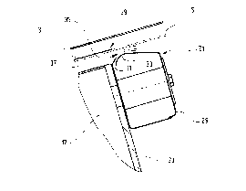
Figur-e 1~ ~ho~ a portion of a dr~er section ~f a web
produ~io~ m~ch~ne, e.g" a paper produ~tion ~a~hlne Within
1$ the dryer sec~ion ~n ~rrangement 1 ma~ be located for guiding
a web of ma~e~ial ~, ~.g., a pape~ web, and a trans~ort belt
5. Tran~port belt 5 may ~uide web 3 ~rom a fir~t dryer
cy~inder 7, around a gui~e roll 9, a~d to a second dryer
cylinder 11. Transport belt 5 and web 3 may be arranged such
that we~ 3 may d~rec~ly abut (or re~ on) the ~urface of dryer
cylinder~ 7, 11 ~nd transport belt 5 may direc~ly abut suide
roll S~ A ~irst ~ree draw 13 ~y ~e lo~ated be~ween ~irst
dryer cyli~der 7 and gulde roll ~ and a se~ond free draw 15
may be located betwee~ ~uide roll 9 and the ~e~on~ dryer
cylinder 11. A web stabi1ize 17 ~ay ~e lo~ated betwee~ fre~
drawe 13 a~d 15 and ~y compri~e, e.g., a suction box to
~uction the are~ of free draws 13 and 15 and, optional}y, to
21 951 42
~5085.S02
suction gui~e ro~l ~. The web ~tabilizer 17 ma~ be util_zed
to 3tabil~ze web ~ on tran~port belt 5 in ~he area of ~ree
draw~ 13 and 15. If ~uide ro~1 9 16 to be ~u~tioned by web
stabili~er 17, then web 3, rl1nn;n~ around the ou~er surface of
S guide roll 9 ~n ~ransport bel~ S, may be suctioned to
tran5port belt 5 ~n~ ~tabilized. Web stabilizer 17 may also
be ~"~ ed of, e.g., a tran~fer ~oil or an air condu~tion
box for t~ans~erring we~ 3 ~rom ~ir5t dryer cylinder ~ ~o
guide roll 9 ~ndlor from 5ulde roli 9 to ~e~ond dryer cylinder
f~, ~1. Fur~he~, web ~ iliz~r 17 may be acted on with ne~a~ive
~nd~or ex~es~ pressure or blast air for transferring ~e~ 3.
In the e~o~tmen~ shown in Figure 1, first dryer cylinder
7 may be a~umed ~o run, e.g., coun~er clockwise a~d 3econd
. dryer cylinder 11 ~ay be assumed to corresp~di ng~ y run
~oun~er ~lockwise. ~uide roll 9, po~itione~ between the d~yer
~ylinders, m~y be as~umed ~o ~orrespondingly run clockwi3e.
Consequently, ~n overhead fixture, e.g., an air conducting
deYice 13, m~y be provide~ near a poin~ A where tran~port belt
5 and we~ 3 are li~ed o~ of the surf~ce o~ dryer cy~inder 7.
2,R Air conduc~ing devl~e 19 may remave or deflect air ~hat ~aæ
been ca~ried alon~ by movement o~ transport bel~ 5 ~nd web 3,
~o th~t the air ~ ot entex in~ the area of ~eb ~tabilizer
17 and adversely a~ t t~e opèxation o the presen~
inven~i~n.
. Web stabilize~ 17 may e~end sub~tanti~lly across the
en~ire wi~th of ~e paper web 3. Preerably, a blower box 21
ma~ be pro~ided in an area adj a~ent to each of the edges of
- 8 --
.. . . . . . I . .. . ... . .. .
` 21 951 42
P15085.gO2
paper ~eb 3. ~lower box ~ hown in Figure 1, may be
~ached t~ a side wa'l 23 o web stabilizer 17 in such a
m~nne~ that blower box 21 may be adjusted and/or regul~ed
independently of web stabilizer 17. Blower box 21 may be
coordinated with a nip 25, ~ormed where p~per web ~ is
separated ~rom the outer ~urface of ~ er cylinder 7. Blower
box 21 mAy include an ~ir in~ake ~onnec~ion Z and may ha~e at
lea~ one blow no2zle directed (opened) toward ~ranepor~ belt
5. ~lower box ~1 ~ay be provided wi~h ~ir ~upplied ~rom,
e.~., ai~ gu~tioned ~ff by the we~ stabilizer which c~n ~e
~o~ ed ~3, e.~., guction box. Alternatively, the ~i~ may
be ~pplied ~ a sep~r~te compressed air ~pply de~ice, e.g.,
a compr~ssor. In the preferred embo~;mer?t, the arrangement
~or blower box 21 may ~e prov~d~d with air suctioned o~ from
web stabilizer 17. Thi~ particular embo~e~t simplifies the
~ru~re o~ the dryer section and ensures a safe tran~fer of
paper web 3 ~rom dryer ~ylinder 7 to guide roll 9, even at
hi~h produ~tion ~paeds.
~gure 2 show~ an alternati~e embodiment of arr~ngement
1 fo~ u~e in a ~y~em in which ~he web of ma~erial 3 ~ay be
trangferred from, e.g., a dryer cylinder 7 to a se~ond dryer
~y}inder 7'. ~he ~ylinder~ ~round ~hi~h pap~r web 3 i~
guid~d, wi~h ~ra~port ~elt 5, ~ay have the ~ame diameter.
Free d~w 13, positioned between the two dryer c~linders 7 and
7', ~y ~e ~s~ign~d a web ~abilizer 17, howe~er, the web
~t~bilizer only acts on one free draw, e,g., between dryer
~ylinder 7 and dryer cylinder 7'.
_ ~ _
~i ~51 42
P1508S.50a
Ag with the em~odiment of Fisure 1, web 3tab~1izer 17 may
extend across the entire w~dth of the paper produc~ion
maçhl~e. Web ~abili~er 17 may i~clude a lateral w~ 3 and
a blower box 21. Blower box ~1 ma~ be a~tached ~o lateral
wall 23' and may ~e arranged in ~he vicinity of the edse of
paper web 3. Blower box 21 may al~o include a plurality o
air ccnnect~ons, e.g., air conne~tions Zl and Z2.
Blower boxes 21, shown in Fig~res 1 and 2, may each be
lo~a~ed a~on~ the ~ide~ (edges) o~ ~ransport belt 5 and ma~
~-L-~ ea~h s~abili2e p~p~r web 3 a~ it is guided on ~ransport belt
5.
Figure 3 show~ a section a m~chine ~or produ~in~ a web
of ma~er~al ln whiçh a web o~ material 3 i~ guided across two
rolls. For example, the web of m~terial 3 can ~e guid~d from
a de~lec~ing roll 27 ~o a dryer cylinder 7. Th~ diame~er of
the dryer cyli~der may be considerably greater than the
diameter of deflecting rol~ ~7. De~lecting roll 27 may ~er~e,
e.g., a~ ~uide roll. It i~ also c~ceiva~le that deflec~ing
rol1 27 may be heated. In the e~bodiment- depic~ed in Figure
3, it is preferred that blower ~ox ~ loca~ed açro~ and
~long free draw 1~. Blower ~ox 21 may in~lude several part3,
~.g., a ~ir~t partial b~ower box ~1' and a ~econd parti~l
blower box ~ln. It i3 al~o conceivable to u~e a plurality of
sm~ll we~ stabilizers to guide web of material 3 in the
~$ vi~inity of ~ree draw 13.
Each o$ the partial blower boxes 21' and 21" ~ay include
~n ~ir intake connection Z. As with the previously de~cr~bed
- 10 -
~. .
~ ~ .
` 2 ! 951 4~
P15085.S02
embo~;~ent~, blower box 21 may be arra~ged in the ~icinity of
an edge o~ web o~ material 3. Blower box 21 of Figure 3 may
~e di~in~ui~hed from ~ho~e ~hown in Figure~ 1 and 2 in that
blower box 21 may extend across the entire length o~ fxee draw
~3. T~us, blower box 21 may a~t as a run-o~f nip 26 at
deflec~ion roll 27 and a5 ~ run-~n nip ~5 at dryer cylinder 7.
H~ver, due to the air carried along by dr~er ~yl~nder 7 and
web o~ material 3, ex~es~ pressure may exist at nip 2S.
D~pending on the flutt~r behavior o web o~ materi~l 3,
~e embo~ nt of Figure 3 ~ay omit one of ~he partial blower
boxe~ 21' and 21" ~o that only run-off nip 2~ or r~n-on nip 25
may be subject to a stabilizing o~ guiding o~ ~he web of
ma~erial.
Figure 4 ~how~ a cros~ ~ection through a blower box ~1.
Blower box 21 may include a hou~ing 2g that i~ ~oupled, in a
3uitab1e ~ner, to an air supply device to ensure excess
pressure within the housing 2~. Air ma~ e~it hou~lng 29
through an ou~-let ~lit ~1, which may open near a bent hou~ing
s~c~ion 33. Outlet slit 31 ma~ ~e desi~ned in su~h a m~nner
that the air ~low~ ~long the bent housing section 33 and ~xit~
th~ough a slit 35 ~a~ m~y be located between housing 29 a~d
~ransport belt S. The air may b~ guided in such a ~nner,
e.~., that a negative pressure is created in a space ~ 7
be~ween we~ ~`t~bilizer 17 ~nd t~an~port belt 5.
2S Alte:~at~v~ly, th~ ydLiv~ ~r~ur~ whi~:h nlay }~ lL r3u~
~o web sta~ilizer 17 may be reinforced. Blower box 21 may be
arr~nged in a vic~ni~y o~ an edge 3~ of web of material 3.
21 951 42
P15085.S02
Thu~, ~he air fro~ blower box ~1 may provide par~icularly 3afe
guidan~e of web edge 2~, e.g., to ~ubstan~iall~ r~duce or
eliminate flutterlng and, thus, prevent the dan~er of a web
break.
In ~iyure 4, tran3port belt 5 i~ shown in two discrete
posi~io~s, ~.e., ~ ~on~inuous line ~how~ a resting po~i~ion of
transport belt S ~nd a bro~en lin~ show~ ~ working position
for tran~port belt S.
Blowex box 21 may be moun~ed on lateral wall 23 of web
~tabilizer 17 and m~y ~e adj~ted and ~et independen~ly ~ro~
the web ~tabilizer in relation to transport belt 5 ~nd web of
m~terial 3. The arrangement of outle~ ~lit 31 may be ~elected
in ~u~h a m~nner ~h~t the exitin~ air pre~e~bl~ sl~des alon~
be~t ho~sing se~ion 33 and delineates ~pace 37 safely again~
1~ the ~urroundi~ out~ide of the paper production ma~hine to
build up a nega ive pressure.
From ~e ~bove dee~ription-~ for Fig~es 1 to 4, it
becomes clear ~ha~ blower boxe~ 21 may prefera~y be in~tallçd
o~ both ~ide~ of web ~bilizer 17 ~o p~e~ent fluttering of
2~ the web ed~e on both ~ide~ of the guided web, Be~ause blower
boxes 2~ ~re designed separately from web ~tabilizer 17,
blowe~ bo~es 21 may b~ adju~ted independe~ly ~rom web
~ ilizer ~7 with regard to tran~port belt 5 and/or web of
material 3, ~o ~hat a safe ne~i~e pre3~ure may be en~ured on
both ~i~es o~ w~b of material 3. I$ blower box 21 ~o~pri~es
se~eral parts or if several small blowex ~oxes are
seq~ent~ally ~xr~nged 3eguenti~11y i~ the area of ~ree draw
. " .. .. ,. . -~ .. . , ., .~ . . . ..
21 951 42
P150~5.S02
1~, the blower ~oxe~ be indepe~dently ad~usted with
respe~ ~o each other ~o optimally adjust to the ru~ of
tran~port be~t 5 and wçb o~ material 3.
Finally, ~he a~ove statements ~ake it ~lear that the
blower ~oxe~ can be worki~ to~ether with we~ 3tabilizers of
a~y desi~ed deYign ~nd r~an thus be applied univer~ally,
~ noted that the orego~ng examples ha~e been
provide~ ~erely for the purpo~e of explanation and are Ln no
way ~o b~ ~on~trued as l~iting of the pre~ent invention.
While ~he invention has been de~c~i~ed with referenae to a
pre~er~ed embodimen~, lt i~ under~tood that the words which
have been u~ed herein are words of description and
illu~ration, rather ~han word~ o~ itation. Changes may be
m~e, w~thin ~e p~rview ~f the appen~e~ c~aim~, a~ pr~ently
~t~ted and a~ amen~d, without delparting from the ~e~ope ~nd
~p~rit of th~ invention in its a~pect~. ~lthough the
invention has been des~ribed herein with re~erence to
par~icular m~n~, material~ and e~bo~i~e~t~, the inventi~n is
nut intended ~o be limited to the particular~ di6clos~d
2R her~in; rather, the i~ven~ion extends to all functiona~ly
equi~alent ~ruc~ure~, method~ and uses, such a~ are wi~hin
th~ scope of ~he a~pended claim~.
- 13 -