Sélection de la langue

Search

Sommaire du brevet 2197637 

Énoncé de désistement de responsabilité concernant l'information provenant de tiers

Une partie des informations de ce site Web a été fournie par des sources externes. Le gouvernement du Canada n'assume aucune responsabilité concernant la précision, l'actualité ou la fiabilité des informations fournies par les sources externes. Les utilisateurs qui désirent employer cette information devraient consulter directement la source des informations. Le contenu fourni par les sources externes n'est pas assujetti aux exigences sur les langues officielles, la protection des renseignements personnels et l'accessibilité.

Disponibilité de l'Abrégé et des Revendications

L'apparition de différences dans le texte et l'image des Revendications et de l'Abrégé dépend du moment auquel le document est publié. Les textes des Revendications et de l'Abrégé sont affichés :

  • lorsque la demande peut être examinée par le public;
  • lorsque le brevet est émis (délivrance).
(12) Brevet: (11) CA 2197637
(54) Titre français: RESERVOIR A FOND PLAT
(54) Titre anglais: FLAT BOTTOM TANK
Statut: Durée expirée - au-delà du délai suivant l'octroi
Données bibliographiques
(51) Classification internationale des brevets (CIB):
  • B65D 25/38 (2006.01)
  • B65D 77/06 (2006.01)
(72) Inventeurs :
  • RUDE, ARTHUR D. (Etats-Unis d'Amérique)
(73) Titulaires :
  • CUSTOM METALCRAFT, INC.
(71) Demandeurs :
  • CUSTOM METALCRAFT, INC. (Etats-Unis d'Amérique)
(74) Agent: GOWLING WLG (CANADA) LLP
(74) Co-agent:
(45) Délivré: 2002-05-28
(22) Date de dépôt: 1997-02-14
(41) Mise à la disponibilité du public: 1997-09-12
Requête d'examen: 1997-04-07
Licence disponible: S.O.
Cédé au domaine public: S.O.
(25) Langue des documents déposés: Anglais

Traité de coopération en matière de brevets (PCT): Non

(30) Données de priorité de la demande:
Numéro de la demande Pays / territoire Date
08/614,269 (Etats-Unis d'Amérique) 1996-03-12

Abrégés

Abrégé français

Réservoir à fond plat permettant l'évacuation complète des liquides par drainage pyramidal dans la tête de fond. Dans un modèle, la tête de fond comporte une partie centrale surélevée en forme de pyramide. Les parois latérales de la tête de fond sont recourbées vers le haut afin de former des parois lisses et courbées. La partie centrale et les parois latérales s'inclinent vers le bas et l'une vers l'autre pour former un axe d'écoulement le long du périmètre de la partie centrale. L'axe d'écoulement s'incline vers le bas à partir d'un premier coin de la tête de fond vers un deuxième coin de la tête de fond, qui est opposé diagonalement au premier coin. Un drain est adjacent au deuxième coin pour permettre d'évacuer les liquides du réservoir.


Abrégé anglais


A flat bottom tank provides for complete drainage of liquid
contents through sloped drainage in the bottom head. The bottom
head has a raised center portion which is pyramidal shaped in one
embodiment. The sides of the bottom head are broken upwardly to
form smooth, rounded wall surfaces. The center portion and the
side walls slope downwardly towards one another to form a line of
flow extending around the perimeter of the center portion. The
line of flow slopes downwardly from a first corner of the bottom
head to a second corner of the bottom head which is diagonally
opposite the first corner. A drain outlet located adjacent the
second corner allows for the drainage of liquid contents from the
tank.

Revendications

Note : Les revendications sont présentées dans la langue officielle dans laquelle elles ont été soumises.


CLAIMS:
1. A method of forming the bottom of a tank for liquids,
said tank having generally upwardly extending sides, comprising
the steps of:
a) providing a square or rectangular shaped bottom
plate member having a plurality of sides and corner portions;
b) forming said bottom plate to provide a raised center
portion which slopes downwardly towards said sides;
c) breaking each of said sides upwardly to form side
wall portions having substantially vertical upwardly extending
wall portions, said side wall portions also having sloped bottom
wall portions which slope downwardly from said vertical upwardly
extending wall portions to meet said center portion of the tank
bottom and thereby form a line of flow, said line of flow
extending around the perimeter of said center portion and having
a downward slope extending from a first one of said corner
portions to a second one of said corner portions, said second
corner being located diagonally opposite said first corner; and
d) forming a drain outlet in the bottom wall portion of
one of the side wall portions adjacent said second corner.
2. The method of claim 1 wherein said center portion is
formed in a pyramidal shape with four triangular shaped planar
surfaces each extending from a center point or vertex downwardly
towards a respective one of said side wall portions and
intersecting said side wall portions at said line of flow.
- 7 -

3. The method of claim 1 wherein said side wall portions
are formed so as to be rounded where the vertical wall portions
meet the sloped bottom wall portions.
4. The method of claim 1 wherein said corner portions are
formed so as to be rounded where adjacent pairs of side wall
portions meet.
5. The method of claim 1 wherein said side wall portions
are formed to be of substantially equal height such that a tank
shell may be easily fitted to the tank bottom.
6. The method of claim 1 wherein said drain outlet is
formed so as to be cylindrical in shape.
7. The method of claim 1 wherein said drain outlet is
spaced apart from said line of flow.
8. The method of claim 7 wherein said drain outlet is
located at a distance of approximately one inch from said line of
flow.
9. The method of claim 1 wherein said drain outlet is
swedged downward such that said bottom wall portion containing
said drain outlet slopes downwardly towards said drain outlet
- 8 -

from the point in said line of flow nearest said drain outlet.
10. The method of claim 1 wherein said center portion and
said side wall portions are formed to meet at said line of flow
such that said line of flow is substantially square or
rectangular in shape and slopes downwardly from said first corner
in both a clockwise and a counterclockwise direction extending
around the perimeter of said center portion.
11. The method of claim 1 which further includes mounting a
support leg on each corner portion, said support legs being of
equal length.
12. The method of claim 11 wherein said tank has four corner
portions with four support legs of equal length mounted thereon.
13. A portable tank for liquids, said tank having generally
upwardly extending sides and a bottom head which provides for
complete drainage of liquid from the tank, wherein said bottom
head comprises a one-piece construction formed from a square or
rectangular shaped bottom plate member having a plurality of
sides and corner portions, said plate member having a raised
center portion which slopes downwardly towards said sides; the
sides of the plate member being broken upwardly to form side wall
portions having substantially vertical upwardly extending wall
portions, said side wall portions also having sloped bottom wall
- 9 -

portions which slope downwardly from the vertical upwardly
extending wall portions to meet the center portion of the tank
bottom and thereby form a line of flow, said line of flow
extending around the perimeter of the center portion and having a
downward slope extending from a first one of the corner portions
to a second one of the corner portions, said second corner being
located diagonally opposite said first corner; and with a drain
outlet formed in the bottom wall portion of one of the side wall
portions adjacent said second corner.
14. The tank of claim 13 wherein said center portion is
formed in a pyramidal shape with four triangular shaped planar
surfaces each extending from a center point or vertex downwardly
towards a respective one of said side wall portions and
intersecting said side wall portions at said line of flow.
15. The tank of claim 13 wherein said side wall portions
are formed so as to be rounded where the vertical wall portions
meet the sloped bottom wall portions.
16. The tank of claim 13 wherein said corner portions are
formed so as to be rounded where adjacent pairs of side wall
portions meet.
17. The tank of claim 13 wherein said side wall portions
are formed to be of substantially equal height such that a tank
- 10 -

shell may be easily fitted to the tank bottom.
18. The tank of claim 13 wherein said drain outlet is
formed so as to be cylindrical in shape.
19. The tank of claim 13 wherein said drain outlet is
spaced apart from said line of flow.
20. The tank of claim 19 wherein said drain outlet is
located at a distance of approximately one inch from said line of
flow.
21. The tank of claim 13 wherein said drain outlet is
swedged downward such that said bottom wall portion containing
said drain outlet slopes downwardly towards said drain outlet
from the point in said line of flow nearest said drain outlet.
22. The tank of claim 13 wherein said center portion and
said side wall portions are formed to meet at said line of flow
such that said line of flow is substantially square or
rectangular in shape and slopes downwardly from said first corner
in both a clockwise and a counterclockwise direction extending
around the perimeter of said center portion.
23. The tank of claim 13 wherein a support leg is mounted on
each corner portion, said support legs being of equal length.
- 11 -

24. The tank of claim 23 wherein said tank has four corner
portions with four support legs of equal length mounted thereon.
- 12 -

Description

Note : Les descriptions sont présentées dans la langue officielle dans laquelle elles ont été soumises.

7b37
FLAT BOTTOM TANR
BACKGROUND AND SUMNARY OF THE INVENTION
The present invention is related to portable tanks and more
particularly to flat bottom tanks having improved drainage
characteristics.
Previous tank bottoms are described in the following U.S.
Pat. Nos: 4,733,790 to Stein; 4,746,034 to Ata et al.; 4,767,021
to Pies; 4,782,973 to Wiese; 5,253,777 to Schutz; 5,316,174 to
Schutz; and 5,346,094 to Strawser.
By the present invention, there is provided a flat bottom
tank with a top head and side walls and a generally square or
rectangular shaped bottom head having four sides and a plurality
of planar surfaces formed in a pyramidal shape which extend from
the center of the bottom head downwardly towards the sides. The
extremities of the sides of the bottom head are broken upwardly
to form a plurality of smooth, rounded wall surfaces which merge
with the side walls of the tank. The bottom head extends
downwardly from the sides to intersect the planar surfaces
sloping downwardly from the center of the bottom head and thereby
form a line of flow which, together with the intersecting planar
surfaces, defines a canal for directing the flow of liquids. The
line of flow extends circumferentially around the interior of the
tank bottom. The line of flow has a high point located near one
corner of the tank bottom and a low point located near the corner
diagonally opposite from the high point corner. A drainage
outlet is formed near the low point of the line of flow for final
drainage of the tank contents. The tank construction of the

21 ~7637
present invention provides for substantially complete drainage of
fluid from the tank.
BRIEF DE8CRIPTION OF THE DRAWINGS
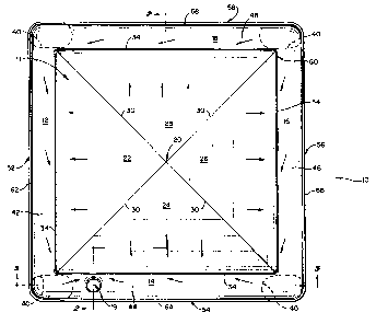
Fig. 1 is a top plan view of the tank bottom of the present
invention, with arrows showing the direction of content drainage.
Fig. 2 is a cross-sectional view of the tank bottom taken
along line 2-2 of Fig. 1.
Fig. 3 is an enlarged detail view of the drain portion of
Fig. 2.
Fig. 4 is a front elevation view of the tank bottom of the
present invention.
Fig. 5 is a cross-sectional view of the tank bottom taken
along line 5-5 of Fig. 1.
DE8CRIPTION OF THE PREFERRED ENBODIMENTS
In the embodiment of the invention as shown in Figs. 1
through 5, there is provided a tank bottom 10 having a central
head portion 11, planar outer head portions 12, 14, 16, 18, and a
drain outlet 19. The central portion 11 is of pyramidal shape
having four triangular shaped planar members 22, 24, 26, 28 which
extend downwardly from a central point or vertex 20 to a line of
flow 34 formed by the intersection of central planar members 22,
24, 26 and 28 with respective outer head portions 12, 14, 16 and
18. The line of flow 34 extends around the perimeter of the
central portion 11. The creases 30 formed by the respective
intersections of planar members 22, 24, 26, 28 extend from the

2 1 976~7
-
central vertex 20 to the line of flow 34. The line of flow 34
thus is basically the intersection of two smoothly contoured
planar surfaces defining a canal which extends around the
periphery of the tank bottom, with no cut channel or indentation
which would interfere with the flow of liquids. This feature is
of particular importance when employing viscous liquids having a
tendency to adhere to side wall surfaces. In one embodiment, the
creases 30 extend to within 4 inches of the sides of the tank.
The tank bottom 10 of the present invention may be flat
stamped or swedged in accordance with procedures known in the
art. Thus the bottom head can be made in different sizes as
required by stamping or swedging of material in a press with
dies.
The tank bottom 10 is supported by legs 40 which, in one
embodiment of the invention, are of equal height. This is an
advantage over prior art tank bottoms which employ one or more
legs of a size taller or shorter than the other legs to
compensate for a sloped bottom. Such prior art tanks are often
misbalanced causing the tank to rock undesirably.
Each outer head portion 12, 14, 16, 18 is broken upwards at
its outer edge so as to have a curved shape which includes a
respective planar bottom wall portion 42, 44, 46, 48 and a
respective upturned vertical portion 52, 54, 56, 58 which
terminates in a respective side wall edge 62, 64, 66, 68. The
edges 62, 64, 66, 68 are formed to merge with the side walls of
the tank. In one embodiment of the invention, the curved shape

2 1 976~7
of each outer head portion 12, 14, 16, 18 is formed with a two
inch radius break. The planar bottom wall portions 42, 44, 46,
48 slope downwardly from the upturned vertical portions 52, 54,
56, 58 towards the line of flow 34 so as to direct the contents
of the tank towards the drainage outlet 19. The side wall edges
62, 64, 66, 68 are of substantially the same height so as to
allow smooth attachment of a tank shell to the tank bottom.
The curved shape of the side wall portions of the tank
bottom 10 provides smooth, rounded corners and sides for optimal
draining. These rounded corners offer an advantage over previous
devices having interior creases or squared edges which are
difficult to clean. This feature of the present invention is
especially important for containers in the food and
pharmaceutical industries as it promotes clean interior surfaces
and allows complete drainage of liquid from the tank.
The line of flow 34 is formed by the intersection of the
central head portion 11 and the outer head portions 12, 14, 16,
18 and slopes downwardly from a high point at corner 60 to the
outlet 19. In a preferred embodiment of the invention, as shown
in Figs. 2 through 5, the line of flow 34 is not indented or
provided with a depth greater than the depth formed by the
intersection of the central and outer head portions. This
prevents the liquid product from collecting along the line of
flow 34 while still allowing the product to flow during drainage.
The line of flow 34 slopes downwardly from the corner point 60
around to the outlet 19 in both a clockwise and a

2 1 9~h37
-
counterclockwise direction to enable fluid being drained from the
tank to travel along either route to the outlet 19. This
configuration helps prevent congestion along any particular route
to the outlet. In one embodiment of the invention, the line of
flow 34 is approximately 3/8 inch lower at the outlet 19 than it
is at corner point 60.
The outlet 19 is formed with a cylindrical shape and is the
same depth as the line of flow 34 at the drainage point. The
outlet 19 is located near the corner which is diagonally opposite
corner point 60 and in one embodiment is approximately two inches
in diameter. The outlet 19 also is positioned exclusively within
outer head portion 14, as shown in Fig. 1, and does not extend
into the line of flow 34 or the central head portion 11. In one
embodiment of the invention, the outlet 19 is positioned so that
its closest edge to the line of flow 34 is located approximately
one inch away from the line of flow 34.
The configuration of the tank bottom central head portion 11
and outer head portions 12, 14, 16, 18 provides for complete
drainage of the liquid contents within the tank. The pyramidal
shape of the central portion 11 and the curved shape of the side
wall portions directs fluid towards the line of flow 34 in all
directions. The line of flow 34 then allows the fluid to pass
along its downward slope until it reaches the outlet 19. The
outlet 19 is swedged downwardly in a smooth contour such that
liquid material within the tank will flow downwardly from the
point of the line of flow 34 nearest the outlet 19 into the

2 1 9763~
,
outlet 19 itself.
The invention may be embodied in other specific forms
without departing from the spirit or essential characteristics
thereof. The present embodiments are therefore to be considered
in all respects as illustrative and not restrictive, the scope of
the invention being indicated by the appended claims rather than
by the foregoing description, and all changes which come within
the meaning and range of equivalency of the claims are therefore
intended to be embraced therein.
What is claimed and desired to be secured by Letters Patent
iS:

Dessin représentatif
Une figure unique qui représente un dessin illustrant l'invention.
États administratifs

2024-08-01 : Dans le cadre de la transition vers les Brevets de nouvelle génération (BNG), la base de données sur les brevets canadiens (BDBC) contient désormais un Historique d'événement plus détaillé, qui reproduit le Journal des événements de notre nouvelle solution interne.

Veuillez noter que les événements débutant par « Inactive : » se réfèrent à des événements qui ne sont plus utilisés dans notre nouvelle solution interne.

Pour une meilleure compréhension de l'état de la demande ou brevet qui figure sur cette page, la rubrique Mise en garde , et les descriptions de Brevet , Historique d'événement , Taxes périodiques et Historique des paiements devraient être consultées.

Historique d'événement

Description Date
Inactive : Périmé (brevet - nouvelle loi) 2017-02-14
Inactive : TME en retard traitée 2016-11-18
Lettre envoyée 2016-02-15
Inactive : CIB de MCD 2006-03-12
Accordé par délivrance 2002-05-28
Inactive : Page couverture publiée 2002-05-27
Préoctroi 2002-03-18
Inactive : Taxe finale reçue 2002-03-18
Un avis d'acceptation est envoyé 2001-10-10
Lettre envoyée 2001-10-10
Inactive : Approuvée aux fins d'acceptation (AFA) 2001-09-19
Inactive : Dem. traitée sur TS dès date d'ent. journal 2001-06-20
Inactive : Renseign. sur l'état - Complets dès date d'ent. journ. 2001-06-20
Inactive : Page couverture publiée 2000-12-21
Modification reçue - modification volontaire 1998-03-17
Lettre envoyée 1997-10-07
Demande publiée (accessible au public) 1997-09-12
Inactive : Demandeur supprimé 1997-08-22
Exigences pour une requête d'examen - jugée conforme 1997-04-07
Toutes les exigences pour l'examen - jugée conforme 1997-04-07

Historique d'abandonnement

Il n'y a pas d'historique d'abandonnement

Taxes périodiques

Le dernier paiement a été reçu le 2002-01-31

Avis : Si le paiement en totalité n'a pas été reçu au plus tard à la date indiquée, une taxe supplémentaire peut être imposée, soit une des taxes suivantes :

  • taxe de rétablissement ;
  • taxe pour paiement en souffrance ; ou
  • taxe additionnelle pour le renversement d'une péremption réputée.

Veuillez vous référer à la page web des taxes sur les brevets de l'OPIC pour voir tous les montants actuels des taxes.

Titulaires au dossier

Les titulaires actuels et antérieures au dossier sont affichés en ordre alphabétique.

Titulaires actuels au dossier
CUSTOM METALCRAFT, INC.
Titulaires antérieures au dossier
ARTHUR D. RUDE
Les propriétaires antérieurs qui ne figurent pas dans la liste des « Propriétaires au dossier » apparaîtront dans d'autres documents au dossier.
Documents

Pour visionner les fichiers sélectionnés, entrer le code reCAPTCHA :


Pour visualiser une image, cliquer sur un lien dans la colonne description du document. Pour télécharger l'image (les images), cliquer l'une ou plusieurs cases à cocher dans la première colonne et ensuite cliquer sur le bouton "Télécharger sélection en format PDF (archive Zip)" ou le bouton "Télécharger sélection (en un fichier PDF fusionné)".

Liste des documents de brevet publiés et non publiés sur la BDBC .

Si vous avez des difficultés à accéder au contenu, veuillez communiquer avec le Centre de services à la clientèle au 1-866-997-1936, ou envoyer un courriel au Centre de service à la clientèle de l'OPIC.


Description du
Document 
Date
(aaaa-mm-jj) 
Nombre de pages   Taille de l'image (Ko) 
Abrégé 1997-05-26 1 20
Description 1997-05-26 6 206
Revendications 1997-05-26 6 160
Dessins 1997-05-26 3 72
Page couverture 1997-05-26 1 14
Page couverture 1997-10-20 1 50
Page couverture 2000-12-11 1 50
Dessin représentatif 2001-09-17 1 16
Page couverture 2002-04-29 1 44
Dessin représentatif 1997-10-20 1 12
Accusé de réception de la requête d'examen 1997-10-07 1 178
Rappel de taxe de maintien due 1998-10-15 1 110
Avis du commissaire - Demande jugée acceptable 2001-10-10 1 166
Avis concernant la taxe de maintien 2016-03-29 1 169
Quittance d'un paiement en retard 2016-11-18 1 162
Correspondance 2002-03-18 1 42
Taxes 1999-01-22 1 32
Taxes 2000-02-02 1 29
Taxes 2001-01-23 1 29