Sélection de la langue

Search

Sommaire du brevet 2197756 

Énoncé de désistement de responsabilité concernant l'information provenant de tiers

Une partie des informations de ce site Web a été fournie par des sources externes. Le gouvernement du Canada n'assume aucune responsabilité concernant la précision, l'actualité ou la fiabilité des informations fournies par les sources externes. Les utilisateurs qui désirent employer cette information devraient consulter directement la source des informations. Le contenu fourni par les sources externes n'est pas assujetti aux exigences sur les langues officielles, la protection des renseignements personnels et l'accessibilité.

Disponibilité de l'Abrégé et des Revendications

L'apparition de différences dans le texte et l'image des Revendications et de l'Abrégé dépend du moment auquel le document est publié. Les textes des Revendications et de l'Abrégé sont affichés :

  • lorsque la demande peut être examinée par le public;
  • lorsque le brevet est émis (délivrance).
(12) Demande de brevet: (11) CA 2197756
(54) Titre français: SOUPAPE DOSEUSE AVEC DETECTION DE PERTE D'ETANCHEITE
(54) Titre anglais: DOSING VALVE HAVING SEAL FAILURE DETECTION
Statut: Réputée abandonnée et au-delà du délai pour le rétablissement - en attente de la réponse à l’avis de communication rejetée
Données bibliographiques
(51) Classification internationale des brevets (CIB):
  • F16K 37/00 (2006.01)
  • B67C 03/28 (2006.01)
(72) Inventeurs :
  • FRANKE, RICKARD (Suède)
  • KANEKO, YUTAKA (Etats-Unis d'Amérique)
  • BRANDSTROM, PER (Etats-Unis d'Amérique)
(73) Titulaires :
  • TETRA LAVAL HOLDINGS & FINANCE S.A.
(71) Demandeurs :
  • TETRA LAVAL HOLDINGS & FINANCE S.A. (Suisse)
(74) Agent: RUSSELL REYNEKE
(74) Co-agent:
(45) Délivré:
(86) Date de dépôt PCT: 1995-09-06
(87) Mise à la disponibilité du public: 1996-04-04
Licence disponible: S.O.
Cédé au domaine public: S.O.
(25) Langue des documents déposés: Anglais

Traité de coopération en matière de brevets (PCT): Oui
(86) Numéro de la demande PCT: PCT/US1995/011419
(87) Numéro de publication internationale PCT: US1995011419
(85) Entrée nationale: 1997-02-17

(30) Données de priorité de la demande:
Numéro de la demande Pays / territoire Date
08/315,408 (Etats-Unis d'Amérique) 1994-09-28

Abrégés

Abrégé français


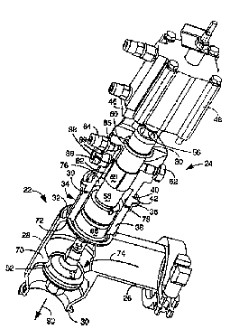
La vanne (20) de dosage du type à piston décrite possède une chambre (76)
scellée hermétiquement derrière le diaphragme (66) qui sépare la partie
asceptique (74) de la vanne (20) de la partie mécanique de la vanne (20). Une
source à vide (84) extérieure est connectée à une ouverture ménagée dans la
chambre (76) ce qui permet de maintenir une pression négative constante à
l'intérieur de la chambre (76). Toute rupture du diaphragme (66) est détectée
par un capteur (88) de pression situé à l'intérieur de la chambre (76)
scellée. Dans un mode de réalisation, une inspection visuelle de la présence
de produits liquides dans la chambre (76) hermétique peut s'effectuer au
travers d'une fenêtre (38) ménagée dans le corps (22, 24) de la vanne de
dosage et située adjacente au diaphragme (66) et à la chambre (76) hermétique.


Abrégé anglais

A piston-type dosing valve (20) is set forth that provides a hermetically sealed chamber (76) behind the diaphragm (66) which separates the aseptic portion (74) of the valve (20) from the mechanical portion of the valve (20). An external vacuum source (84) is connected to an opening in the chamber (76) thereby maintaining a constant negative pressure within the chamber (76). Any breach in the diaphragm (66) will be detected by a pressure sensor (88) located within the sealed chamber (76). In one embodiment, visual inspection for the presence of liquid product in the sealed chamber (76) can be accomplished through a window (38) in the dosing valve housing (22, 24) located adjacent to the diaphragm (66) and sealed chamber (76).

Revendications

Note : Les revendications sont présentées dans la langue officielle dans laquelle elles ont été soumises.


WE CLAIM:
1. [CANCELED]
2. [CANCELED]
3. [CANCELED]
4. A dosing valve comprising:
a) an elongated cylindrical housing
having an outlet at a first end and an
inlet through a sidewall defining a
path for product to pass through the
housing, the housing further having a
flange at a second end thereof;
b) a connection cylinder at the second
end of the elongated housing, the
connection cylinder having a first end
adjacent the second end of the
elongated housing, a second end, and a
viewing opening disposed through a
sidewall thereof;
c) a valve seat disposed between the
outlet and the inlet;
d) a plug adapted to engage the valve
seat thereby sealing the inlet from
the outlet;
12

e) a rod attached to the plug and
extending therefrom into the
connection cylinder at the second end
of the housing;
f) a rod drive attached at the second end
of the housing for moving the rod
between a first position in which the
plug engages the valve seat and a
second position in which the plug
disengages the valve seat;
g) a flexible diaphragm mounted about the
second end of the housing and sealing
the connection cylinder from the path
of product, the flexible diaphragm
flexing with movement of the rod, the
flexible diaphragm having a flange;
and
h) a transparent sleeve dimensioned to
fit within and seal with the
connection cylinder, the transparent
sleeve allowing direct visual
observation of the flexible diaphragm
through the viewing opening of the
connection cylinder; and
13

g) means sealing the second end of the
connection cylinder, the transparent
sleeve having a first end securing the
flange of the flexible diaphragm
against the flange of the elongated
housing and a second end adjacent the
sealing means.
5. [CANCELED]
6. A dosing valve as claimed in claim 4 wherein the
sealing means and diaphragm define a
hermetically sealed chamber, the dosing
valve further comprising:
a) a vacuum source in communication with
the sealed chamber for maintaining a
negative pressure within the chamber;
and
b) a pressure sensor in communication
with the sealed chamber to monitor
pressure therein, a rise in pressure
being indicative of a breach of the
diaphragm.
14

7. A dosing valve comprising:
a) a housing having an inlet and an
outlet defining a path through which
product enters and exits the housing;
b) a connection cylinder extending from
one end of the housing, the connection
cylinder having a first end adjacent
the housing, a second end, and a
viewing opening disposed through a
sidewall thereof;
c) a valve disposed within the housing
between the inlet and the outlet;
d) a mechanical drive connected to the
valve adapted to open and close the
valve;
e) a flexible diaphragm within the
housing separating the path of the
product from the mechanical drive, the
flexible diaphragm being movable with
the mechanical drive during operation
of the dosing valve;
f) sealing means disposed proximate the
second end of the connection cylinder,

the flexible diaphragm and the sealing
means forming a hermetically sealed
chamber; and
g) a transparent sleeve dimensioned to
fit within and seal with the
connection cylinder, the transparent
sleeve allowing direct visual
observation of the flexible diaphragm
through the viewing opening of the
connection cylinder.
8. A dosing valve as claimed in claim 7 and further
comprising:
a) a vacuum source in communication with
the hermetically sealed chamber for
maintaining a negative pressure within
the chamber; and
b) a pressure sensor in communication
with the sealed chamber to monitor
pressure therein, a rise in pressure
being indicative of a breach of the
diaphragm.
16

Description

Note : Les descriptions sont présentées dans la langue officielle dans laquelle elles ont été soumises.

~ WO9C110145 2 1 ~ 7 7 5 6 PCT~S95111419
DOSING VALVE HAVIN~ SEAL FAILURE D~c~ l~N
L~:~iNl~:AL ET~!T.n
The present invention relates generally to
automated filling ~-~h;nPs for liquid containers and
pertains, more specifically, to a dosing valve
embodying elements which allow vi9ual and electrical
detection of a faulty seal in the sterile valve
environment.
BAI.;~CUUNLI
A variety of dosing devices for liquid or
semi-viscous products are known for use in automated
lC filling ~-rh;n~g. These valves serve to allow a
predetermined amount of product to flow from a
product supply reservoir into a container.
One valve that is commonly used in automated
filling ---h;n~c is a piston valve. A piston valve
typically includes an elongated, cylindrical housing
with an outlet at the bottom end of the housing. An
inlet in the side of the housing above the outlet
allows product to flow into the housing. A valve
seat defines the separation between the inlet and
the outlet. A plug sits against the outlet side of
the valve seat. The plug is attached to a rod which
runs coaxially with the housing from the plug to a
pneumatic rod drive attached at the top of the
housing. When the rod is forced downward by the rod
drive, the plug disengages the valve seat allowing
.. . , . . . _ ... .. .. ... _ . .

WO9~tOI45 ~ 2 1 9 7 7 5 6 rcT~s9~ll4l9 ~
product to flow from the inlet to the outlet. This
downward position is held until the desired amount
of product has flowed through the valve. Then the
rod drive ~pulls the rod upwards forcing the plug
against the valve seat. This prevents product from
flowing through to the outlet until a new container
is in place for filling.
The shelf life of liquid products such as milk
or juice is directly related to the amount of
cmnt~mi n~nts allowed to come into contact with the
product before being sealed in the sterile
environment of a container. The greater the amount
of the contnm;n~nts, the lower the shelf life.
Therefore, maintaining a sealed aseptic environment
for the product as it passes through a valve is
desirable. It is also desirable to maintain a seal
between the liquid product and the L~ ; ni ng
mechanical portions of the valve to avoid fouling of
the valve or corrosion o~ its parts.
The manufacturers of piston-type dosing valves
have attempted to solve the above mentioned problem~
by attaching a flexible diaphragm around the rod to
the interior wall of the housing above the inlet
thereby sealing the mechanical portion of the valve,
includin~ the pneumatic rod dri~e, from the path of
the product. The diaphragm is an effective seal as
long as the diaphragm remains intact but, because
the diaphragm is continuously being stretched b-~

~ WO96110145 2 1 9 7 7 5 6 - PCT~S95/~1419
movement of the rod and pressure of the product, the
diaphragm material tends to fatigue. This creates
the further problem of detecting a breach in the
diaphragm seal. Currently, the only way to
accomplish such detection is by shutting down the
filling machine and disassembling the valve.
Machine downtime and labor of a machine technician
add to the cost of the final product.

2 1 97756
WO9611014S r~ 419
snMMaR~ OF TEE LNV~L~Ll~
h dosing valve i~ set forth that overcomes many
of the problems of the prior art by providing a
hermetlcally sealed chamber behind the diaphragm
which separates the aseptic pOrtiQn of the valve
from the mechanical portion of the valve. Ar.
external vacuum source is connected to an opening in
the chamber thereby maintaining a constant negative
pressure within the chamber. Any breach in the
diaphragm will be detected by a pressure or contact
sensor located within the sealed chamber. In one
embodiment, ~isual inspection ~or the presence of
liquid prcduct in the sealed chamber can be
accomplished through a window in the dosing valve
housing located ad~acent to the diaphragm and sealed
chamber.

~ WO9611014~ 2 1 9 7, 5 6 PCT~S95111419
BRIEF D3S~~ u1. OF DRAWINGS
FIG. 1 is an exploded view of a dosing valve.
FIG. 2 is a perspective sectional view of the
dosing valve of FIG l.
FIG. 3 is a perspective view oE the glass
sleeve of FIG. l.
FIG. 4 is a side view of the glass sleeve of
FIG. l.

2i9775~
W0~6tlO14~ PCT~S9~111419
~8~1V~l~. OF ~eoe pR~ EMBODrMENT
FIG. l illustrates a piston-type dosing valve
embodying elements which allow visual and
electrical detection of a faulty seal. The valve
housing i8 made up of a lower valve body 22 and an
upper valve body 24. The lower valve body 22 has a
generally cylindrical interior (not shown). In
communicat~on with the interior of the lower valve
body 22 i5 an inlet 26 which enters through a
sidewall 28 of the lower valve body. The inlet 26
can be connected to s product reservoir (not shown
in EIG. l~. Also in communication with the interior
of the lower valve body 22 is a circular outlet 30
at one end of the lower valve body a2. A circular
valve seat (not shown in EIG. l) is formed on the
inner surface of the sidewall 28 of the lower valve
body 22 between the inlet 26 and the outlet 30.
At the other end of the lower ~alve body 22 is
a conneCtiDn cylinder 32 for connecting the lower
valve body 22 to the upper valve body 24. A pair of
viewing ports 34 ~only one shown) are cut out of the
sidewall of the connection cylinder 32 and a rim 36
is formed about the end of the connection cylinder
32. A cylindrical transparent sleeve 38 made of,
for example, hardened glass fits concentrically
inside the connection cylinder 8a. An o-ring 39
slts in a channel (not shown in FIG. l) in the end
of the transparent sleeve 39.

~ WO96/i014~ 2 1 9 7 7 5 ~ PCT~S9~/11419
The upper valve body 24 has a connection lip 40
at one end which is complementary to the connection
cylinder 32 of the lower valve body 22. A flange 42
is formed about the connection lip 40. This
connection lip 40 has substantially the same outer
diameter as the transparent sleeve 38 so it can
slide into connection cylinder 32 to sealingly
engage the o-ring 39 and transparent sleeve 38. The
upper valve body 24 is connected to the lower valve
body by a clamp 44 which engages the flanges 36 and
42.
A mounting block 46 is formed at the other end
of the upper valve body 24 to which is mounted a
pneumatic rod drive 48. A bore ~not shown in FIG.
l) is formed through the interior of the upper valve
body 24 which is in axial alignment with the rod
drive 48 and the valve seat ~not shown in FIG. l) of
the lower valve body 22.
Opening and closing of the valve 20 is effected
by engagement and ~lc~ngagement of the plug cap 50
and plug ring 52 with the outlet side of the valve
seat (not shown in FIG. I~. The plug cap 50 i8
connected by a valve stem 54 to a rod 56 which is,
in turn1 connected to be driven by the rod drive 48.
The plug ring 52 is engaged between the plug cap 50
and a flange 57 of the valve stem 54. A plunger 58
is connected to the valve stem 54 for co-movement
with the valve stem 54 and the rod 56. The plunger

:
WO96~10145 2 l 9 7 7 5 6 rcT~sg~ 4l9 ~
58 made of, for example, stainless steel i6 slidably
secured by a bushing 59 made of, for example,
plastic within the bore in the upper valve body 24
which allows the plunger 58 and rod 56 to slide
axially in the bore. A sealing ring 60 which
sealingly engages the plunger 58 is also mounted
within the bore. A screw 62 enters through the
6idewall of the upper valve body 24 and slidingly
engages a channel 64 in the plunger 58 thereby
limiting the axial movement of the rod 56 and
preventing rotation thereof.
A fle~lble circular diaphragm 66 is engaged at
its interior edge between an upper flange 68 of the
valve ste~ 54 and the plunger 55. The diaphragm 66
i8 also secured at its exterior edge by engagement
between the transparent sleeve 38 and a ridge formed
on the inside of the sidewall 28 pro~i~ate the inlet
26. The diaphragm 66, for example, is made of an
FDA approved silicone elastomer having a ~omex
polymide fabric with a thread count of 62 X 58
threads~inch having a tensile 5trength of 145 X 135
pounds/inch.
FIG. 2 shows a perspective sectional view of
the dosing valve 20 illustrating the orientation of
its parts when assembled. The interior of the lower
valve body 22 and upper valve body 24 are revealed
to show the valve seat 70 and the ridge 72 for
engaging the outer edge of the diaphragm 66.

~ WO9611014~ 2 1 9 7 7 ~ 6 PCT~Sg~11419
The interior cavity defined within the upper
and lower valve bodies 22 and 24 is divided by the
diaphragm 66. The diaphragm 66 seals the aseptic
product path (indicated by arrow 74) from a chamber
76 surrounding the plunger 58. The chamber 76 is
hermetically sealed and is defined by the diaphragm
66 at its lower end, by the sealing ring 60 at its
upper end, and by the transparent sleeve 38 and the
inner wall 78 and bore 80 of the upper valve body
24.
A bore 82 in the inner wall 78 running parallel
to the bore 80 is in fluid communication with the
chamber 76. A vacuum line 84 is connected to the
bore 82 through a hole 85 in the upper valve body
24. This vacuum line 84 is connected to a vacuum
source (not shown) which ~-in~inq a negative
pressure of, for example, 80~ of atmospheric
pressure within the chamber 76. An adaptor 86 holds
a pressure or contact sensor 88 within another hole
89 through the upper valve body 24 to the bore 82.
This sensor 88 is electrically connected to a
monitoring circuit which detects any rise in the
pressure within the chamber 76 or, if a contact
sensor is used, the presence of liquid draw into the
chamber 76 by the under-pressure. Such a rise in
pressure or the pressure of liquid will be
indicative of a breach in the diaphragm 66.
Alternatively, a contact sensor may be used at 88

2l977~6
WO96~1~145 ~ PCT~S~ 19
and~or an external pressure sensor may be used
exterior to the dosing valve.
As can be seen, downward a~ial movement
(indicated by arrow 90) of the rod 56, plunger 58
and valve stem 54 will cause the plug ring 52 to
disengage the valve 6eat 70. The diaphragm 66 is
flexible allowing it to move with the valve stem 54
and plunger 58. Closing of the valve by upward
force of the rod drive 48 is desirably expedited
because the negative pressure within the chamber 76
behind the diaphragm 66 creates additional upward
force on the diaphragm 66.
The chamber 76 and diaphragm 66 can also be
visually inspected through the transparent sleeve
38. The presence of product in the chamber 76 will
visually indicate a breach in the diaphragm 66.
FICs. 3 and 4 illustrate the transparent sleeve
38 in greater detail. As can be seen, in FIC~. 4,
the end o~ the transparent sleeve 38 that sealingly
engages the diaphragm 66 has a concentric inner
flange lO;0 which extends ~elow the outer rim 102.
The end of the transparent sleeve 38 that sealingly
engages the connection lip 40 of the upper valve
body 24 has a concentric channel 104 creating an
inner rim 106 and an outer rim 108. The o-ring 49
(shown in FIGs. l and 2) sit6 partially in this
channel 104.

~ Wo ~/10145 2 1 q 7 ~ 5 ~ PCT~S9~/11419
Although the present invention has been
described with reference to a specific embodiment,
those of skill in the art will recognize that
changes may be made thereto without departing from
the scope and spirit of the invention as set forth
in the appended claims.

Dessin représentatif
Une figure unique qui représente un dessin illustrant l'invention.
États administratifs

2024-08-01 : Dans le cadre de la transition vers les Brevets de nouvelle génération (BNG), la base de données sur les brevets canadiens (BDBC) contient désormais un Historique d'événement plus détaillé, qui reproduit le Journal des événements de notre nouvelle solution interne.

Veuillez noter que les événements débutant par « Inactive : » se réfèrent à des événements qui ne sont plus utilisés dans notre nouvelle solution interne.

Pour une meilleure compréhension de l'état de la demande ou brevet qui figure sur cette page, la rubrique Mise en garde , et les descriptions de Brevet , Historique d'événement , Taxes périodiques et Historique des paiements devraient être consultées.

Historique d'événement

Description Date
Le délai pour l'annulation est expiré 2001-09-06
Demande non rétablie avant l'échéance 2001-09-06
Réputée abandonnée - omission de répondre à un avis sur les taxes pour le maintien en état 2000-09-06
Lettre envoyée 1997-10-09
Demande publiée (accessible au public) 1996-04-04

Historique d'abandonnement

Date d'abandonnement Raison Date de rétablissement
2000-09-06

Taxes périodiques

Le dernier paiement a été reçu le 1999-09-02

Avis : Si le paiement en totalité n'a pas été reçu au plus tard à la date indiquée, une taxe supplémentaire peut être imposée, soit une des taxes suivantes :

  • taxe de rétablissement ;
  • taxe pour paiement en souffrance ; ou
  • taxe additionnelle pour le renversement d'une péremption réputée.

Les taxes sur les brevets sont ajustées au 1er janvier de chaque année. Les montants ci-dessus sont les montants actuels s'ils sont reçus au plus tard le 31 décembre de l'année en cours.
Veuillez vous référer à la page web des taxes sur les brevets de l'OPIC pour voir tous les montants actuels des taxes.

Historique des taxes

Type de taxes Anniversaire Échéance Date payée
Enregistrement d'un document 1997-07-04
TM (demande, 2e anniv.) - générale 02 1997-09-08 1997-09-03
TM (demande, 3e anniv.) - générale 03 1998-09-08 1998-09-01
TM (demande, 4e anniv.) - générale 04 1999-09-07 1999-09-02
Titulaires au dossier

Les titulaires actuels et antérieures au dossier sont affichés en ordre alphabétique.

Titulaires actuels au dossier
TETRA LAVAL HOLDINGS & FINANCE S.A.
Titulaires antérieures au dossier
PER BRANDSTROM
RICKARD FRANKE
YUTAKA KANEKO
Les propriétaires antérieurs qui ne figurent pas dans la liste des « Propriétaires au dossier » apparaîtront dans d'autres documents au dossier.
Documents

Pour visionner les fichiers sélectionnés, entrer le code reCAPTCHA :


Pour visualiser une image, cliquer sur un lien dans la colonne description du document (Temporairement non-disponible). Pour télécharger l'image (les images), cliquer l'une ou plusieurs cases à cocher dans la première colonne et ensuite cliquer sur le bouton "Télécharger sélection en format PDF (archive Zip)" ou le bouton "Télécharger sélection (en un fichier PDF fusionné)".

Liste des documents de brevet publiés et non publiés sur la BDBC .

Si vous avez des difficultés à accéder au contenu, veuillez communiquer avec le Centre de services à la clientèle au 1-866-997-1936, ou envoyer un courriel au Centre de service à la clientèle de l'OPIC.

({010=Tous les documents, 020=Au moment du dépôt, 030=Au moment de la mise à la disponibilité du public, 040=À la délivrance, 050=Examen, 060=Correspondance reçue, 070=Divers, 080=Correspondance envoyée, 090=Paiement})


Description du
Document 
Date
(aaaa-mm-jj) 
Nombre de pages   Taille de l'image (Ko) 
Revendications 1996-04-03 5 110
Dessins 1996-04-03 3 66
Abrégé 1996-04-03 1 69
Description 1996-04-03 11 310
Dessin représentatif 1997-06-11 1 16
Courtoisie - Certificat d'enregistrement (document(s) connexe(s)) 1997-10-08 1 116
Courtoisie - Lettre d'abandon (taxe de maintien en état) 2000-10-03 1 184
Taxes 1998-08-31 1 35
Taxes 1997-09-02 1 38
Taxes 1999-09-01 1 35
Rapport d'examen préliminaire international 1997-02-16 9 283
Courtoisie - Lettre du bureau 1997-03-24 1 38