Sélection de la langue

Search

Sommaire du brevet 2198575 

Énoncé de désistement de responsabilité concernant l'information provenant de tiers

Une partie des informations de ce site Web a été fournie par des sources externes. Le gouvernement du Canada n'assume aucune responsabilité concernant la précision, l'actualité ou la fiabilité des informations fournies par les sources externes. Les utilisateurs qui désirent employer cette information devraient consulter directement la source des informations. Le contenu fourni par les sources externes n'est pas assujetti aux exigences sur les langues officielles, la protection des renseignements personnels et l'accessibilité.

Disponibilité de l'Abrégé et des Revendications

L'apparition de différences dans le texte et l'image des Revendications et de l'Abrégé dépend du moment auquel le document est publié. Les textes des Revendications et de l'Abrégé sont affichés :

  • lorsque la demande peut être examinée par le public;
  • lorsque le brevet est émis (délivrance).
(12) Brevet: (11) CA 2198575
(54) Titre français: AJUSTEMENT D'UN ASSEMBLAGE DE POIGNEE PAR LA DISPOSITION POINT PAR POINT
(54) Titre anglais: ADJUSTING KNOB ASSEMBLEY WITH DISCRETE POSITIONING
Statut: Périmé et au-delà du délai pour l’annulation
Données bibliographiques
(51) Classification internationale des brevets (CIB):
  • G05G 1/12 (2006.01)
  • G05G 5/06 (2006.01)
  • H01H 19/11 (2006.01)
  • H01H 71/74 (2006.01)
(72) Inventeurs :
  • KOLBERG, KENNETH DANIEL (Etats-Unis d'Amérique)
  • PARKS, DAVID ALLEN (Etats-Unis d'Amérique)
  • MORRIS, KIMBERLEY (Etats-Unis d'Amérique)
  • SCHACHNER, JAMES ROBERT (Etats-Unis d'Amérique)
(73) Titulaires :
  • EATON CORPORATION
(71) Demandeurs :
  • EATON CORPORATION (Etats-Unis d'Amérique)
(74) Agent: SMART & BIGGAR LP
(74) Co-agent:
(45) Délivré: 2004-12-14
(22) Date de dépôt: 1997-02-26
(41) Mise à la disponibilité du public: 1997-08-27
Requête d'examen: 2002-02-26
Licence disponible: S.O.
Cédé au domaine public: S.O.
(25) Langue des documents déposés: Anglais

Traité de coopération en matière de brevets (PCT): Non

(30) Données de priorité de la demande:
Numéro de la demande Pays / territoire Date
607,677 (Etats-Unis d'Amérique) 1996-02-27

Abrégés

Abrégé anglais


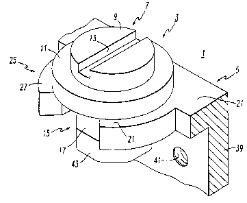
An adjusting knob assembly includes a knob member having a knob and
an axially extending shaft. A support bracket has an aperture defined in part
by a
gapped ring section formed by a pair confronting arcuate fingers. The shaft
and the
aperture have complimentary, longitudinally extending, circumferentially
distributed
flat surfaces, which provide discrete angular positions for the shaft when the
complimentary flat surfaces are in register. Preferably, the gap between the
confronting fingers is sized, and the arcuate fingers have a compliance
sufficient that
the shaft may be passed laterally through the gap and snapped into the
aperture. Any
one of a plurality of interchangeable cam members can be press fit on to the
end of the
shaft.

Revendications

Note : Les revendications sont présentées dans la langue officielle dans laquelle elles ont été soumises.


-6-
THE EMBODIMENTS OF THE INVENTION IN WHICH AN EXCLUSIVE
PROPERTY OR PRIVLEGE IS CLAIMED ARE DEFINED AS FOLLOWS:
1. An adjusting knob assembly comprising:
a knob member having a knob and a shaft extending axially from
said knob and terminating in a free end; and
a support bracket having an aperture defined at least in part by
a compliant, gapped ring section, one of the shaft and aperture having a
plurality of
longitudinally extending, circumferentially distributed flat surfaces, and the
other
having at least one complimentary flat surface, said shaft and aperture being
dimensioned such that said shaft is pliantly retained at any of a plurality of
rotational
positions within said aperture at which said flat surfaces on said shaft and
aperture are
in register.
2. The adjusting knob assembly of Claim 1 wherein said shaft has
said plurality of longitudinally extending circumferentially distributed flat
surfaces with
cylindrical surfaces between said flat surfaces.
3. The adjusting knob assembly of Claim 2 wherein said gapped ring
section is formed by a pair of confronting compliant arcuate fingers spaced
apart to
form a gap, said gap having a width and said arcuate fingers having a
compliance
sufficient for said shaft to be passed laterally through said gap into said
aperture.
4. The adjusting knob assembly of Claim 3 wherein said arcuate
fingers have beveled outer corners for guiding said shaft laterally into said
gap.
5. The adjusting knob assembly of Claim 4 where said arcuate
fingers each have one of the complimentary flat surfaces adjacent said gap.
6. The adjusting knob assembly of Claim 5 where in said plurality
of longitudinally extending flat surfaces are equiangularly circumferentially
distributed
on said shaft.

-7-
7. The adjusting knob assembly of Claim 1 wherein said gapped ring
section is formed by a pair of confronting compliant arcuate fingers spaced
apart to
form a gap, said gap having a width and said arcuate fingers having a
compliance
sufficient for said shaft to be passed laterally through said gap into said
aperture.
8. The adjusting knob assembly of Claim 7 wherein said arcuate
fingers have beveled outer corners for guiding said shaft laterally into said
gap.
9. The adjusting knob assembly Claim 8 wherein said arcuate
fingers each have one of the complimentary flat surfaces adjacent said gap.
10. The adjusting knob assembly of Claim 9 wherein said shaft has
eight equiangularly spaced flat surfaces circumferentially distributed, and
where in said
aperture has a third complimentary flat surface centered opposite said gap.
11. The adjusting knob assembly of Claim 10 wherein said shaft has
cylindrical surfaces between said longitudinally extending flat surfaces, and
wherein
said aperture has complimentary cylindrical surfaces on said aperture between
the
complimentary flat surfaces on said aperture.
12. The adjusting knob assembly of Claim 11 including a cam
member on said free end of said shaft.
13. The adjusting knob assembly of Claim 1 including a cam member
on said free end of said shaft.
14. The adjusting knob assembly of Claim 13 wherein said cam
member is a separate piece from said shaft, and including mounting means
securing
said cam member to said shaft, said cam member being one of a plurality of
interchangeable cam members.

Description

Note : Les descriptions sont présentées dans la langue officielle dans laquelle elles ont été soumises.


- 1 - 95-PDC-382
ADJUSTING KNOB ASSEMBLY WITH
DISCRETE POSITIONING
BACKGROUND OF THE INVENTION
Field of the Invention
This invention relates to rotatable adjusting knobs, and particularly to
an adjusting knob assembly including a positioner which locates the rotatable
knob at
discrete angular positions.
Background Information
There are many applications for rotatable adjusting knobs where it is
desirable to position a knob at a number of discrete angular positions. One
such
adjustable knob utilizes a ball housed in a radial bore in a collar supporting
a knob
shaft. The ball is spring biased to bare against flats on the shaft to
establish the
discrete angular positions of the knob. Such an arrangement is effective, but
requires
a number of parts which must be fabricated and assembled. It also requires
considerable space which is not always available.
There is a need for an improved adjusting knob assembly which is
simple yet effective in retaining the knob at discrete angular positions.
There is an additional need for such an improved adjusting knob
assembly which can be economically fabricated and assembled.
There is also a need for such an improved adjusting knob assembly
which requires minimum space.
SUMMARY OF THE INVENTION
These needs and others are satisfied by the invention which is directed
to an adjusting knob assembly which includes a knob member having a knob and a
shaft extending axially from the knob. A support bracket which also serves as
a

~~9~~7g~
l
- 2 - 95-PDC-382
positioner has an aperture defined at least in part by a compliant, gapped,
ring section.
One of the shaft and the aperture has a plurality of longitudinally extending,
circumferentially distributed flat surfaces. The other of the shaft and
aperture has at
least one complimentary flat surface. The shaft and aperture are dimensioned
such that
the shaft is plurality retained at any of the polarity of rotational positions
in the
aperture at which the flat surfaces on the shaft and the aperture are in
register.
Preferably, the aperture is formed by a pair of confronting arcuate
fingers spaced apart to form the gap. The gap has a width and the fingers have
a
compliancy such that the shaft can be passed laterally through the gap and
snapped into
the aperture. Also preferably, the outer corners of the arcuate fingers are
beveled to
serve as guides for insertion of the shaft into the aperture through the gap.
In a particularly useful embodiment of the invention, the- shaft is
provided with eight longitudinally extending flat surfaces equiangularly
spaced
circumferentially and the aperture is provided with a pair of complimentary
flat
surfaces on the confronting arcuate fingers adjacent to the gap and a third
complimentary flat surface centered opposite the gap. Preferably, cylindrical
surfaces
are formed on the shaft between the adjacent flats to reduce wear. Also
preferably,
the aperture has a complimentary cylindrical surfaces between the
complimentary flat
surfaces on the aperture.
As another aspect of the invention, a cam member is provided on the
free end of the shaft. This cam member can have a radial and/or axially facing
cam
surface. The cam member can be one of a number of interchangeable cam members
engaged by the end of the shaft to provide a suitable adjustment pattern for
the
particular application.
BRIEF DESCRIPTION OF THE DRAWINGS
A full understanding of the invention can be gained from the following
description of the preferred embodiments when read in conjunction with the
accompanying drawings in which:
Figure 1 is an isometric view of an adjusting knob assembly in
accordance with the invention.
Figure 2 is an exploded isometric view of the adjusting knob assembly
of Figure 1 rotated 90° from the orientation of Figure 1.

y ~ 2 1 ~~~7 9
- 3 - 95-PDC-382
Figure 3 is a fragmentary, sectional view in enlarged scale illustrating
features of the preferred embodiment of the invention.
DESCRIPTION OF THE PREFERRED EMBODIMENT
Referring to the drawings, the adjusting knob assembly 1 of the
invention includes a knob member 3 and a support bracket 5 which also serves
as a
positioner. The knob member 3 comprises a knob 7 which includes a knob head 9
projecting axially beyond a knob flange 11. The knob head 9 is shown in the
exemplary embodiment as a cylindrical member having a slot 13 for insertion of
a
screw driver. The particular configuration of the knob is not an essential
feature of the
invention. For instance, the knob could be fluted or ribbed for grasping with
the
fingers, and could be polygonal in cross-section, or any other configuration.
The
particular slotted head 9 shown is useful for instance, in making adjustments
in trip
settings of a thermal-magnetic circuit breaker, but it will be understood that
this is an
exemplary use only.
The knob member 3 further includes a shaft 15 extending axially from
the knob 7. The shaft 15 has a plurality of axially extending,
circumferentially spaced
flat surfaces 17. The exemplary shaft has 8 such flat surfaces 17
equiangularly spaced.
As best seen in Figure 3, cylindrical sections 19 are preferably provided on
the shaft
15 between the flat surfaces 17. Other numbers of flat surfaces could be
provided
dependent upon the number of discrete angular positions desired.
The support bracket 5 includes a planar body 21 which defines an
aperture 23. The aperture 23 is formed in part by a compliant, gapped ring
section 25
of the planar body 21. This gapped, ring section 25is formed bya pair of
confronting
arcuate fingers 27 spaced apart to form the gap 29. The arcuate fingers 27
have a
compliance, and the gap 29 has a width, such that the shaft 15 of the knob
member 3
can be pushed laterally through the gap 29 and snapped into the aperture 23.
Beveled
outer corners 31 on each of the arcuate fingers 27 serve as guides for
inserting the
shaft and wedge the arcuate fingers apart to enable the shaft to pass through
the gap
29.
The aperture 23 has axially extending flat surfaces two of which 33 are
on the ends of the arcuate fingers 27 adjacent gap 29. These flat surfaces are
complimentary to the flat surfaces 17 on the shaft. A thud complimentary flat
surface
in the aperture 23 is centered opposite the gap 29. The remaining surface 37
of the

- 4 - 95-PDC-382
aperture is cylindrical and complimentary to the cylindrical surfaces 19 on
the knob
shaft 15.
The support bracket 5 has an arrangement for mounting the knob
assembly in an appropriate location within a device in which the knob is to be
used.
In the exemplary arrangement, the support bracket 5 has a mounting flange 39
with
mounting holes 41 for receipt of suitable fasteners (not shown). .
The knob member 3 also includes an engagement member 43 for
engaging the device to be adjusted with the knob. In the exemplary assembly 1
this
engagement member is in the form of cam member. Preferably, the cam member 43
is removably secured to the free end 45 of the knob shaft 15 so that a
plurality of
interchangeable cam members 43 can be used with a standard knob member 3. In
the
exemplary adjusting knob assembly, the cam member 43 is removably secured to
the
shaft 15 by a mount 46 which includes an axially projecting pin 47 on the
shaft 15 and
an aperture 49 in the cam member 43. The pin 47 is keyed by a flat surface 51
which
engages a similar flat 53 in the aperture 49 to assure that the cam member
rotates with
the knob shaft 15. The exemplary cam member 43 has an axial facing caroming
surface 55. Alternatively, the caroming surface could face radially.
In use, the support bracket 5 it mounted in a desired location using
fasteners (not shown) inserted through the mounting holes 41 in the flange 39.
The
appropriate interchangeable cam member 43 is press fit on to the pin 47 on the
knob
shaft 15. The knob shaft ~15 is inserted in the gap 29 and pressed laterally
to spread
arcuate fingers 27 apart through the wedging action produce by the beveled
corners 31
until the shaft snaps into place in the aperture 23. The knob member 3 can
then be
rotated to any one of eight angular positions in which the flat surfaces 17 on
the shaft
15 register with the complimentary flat surfaces 33 and 35 in the aperture 23.
The
support bracket 5 is preferably molded from a material having a compliance
sufficient
for the arcuate fingers to spread apart as the knob is rotated and to
initially allow the
. lateral insertion of the shaft 15 into the aperture 23. A suitable material
is a resin such
as polycarbonate. The knob member 3 may be molded of a similar material,
although
this is not required.
The adjustable knob assembly of the invention provides a simple,
inexpensive, easily produced adjustment device which requires very little
space.

~9~~a
- 5 - 95-PDC-382
While specific embodiments of the invention have been described in
detail, it will be appreciated by those skilled in the art that various
modifications and
alternatives to those details could be developed in light of the overall
teachings of the
disclosure. Accordingly, the particular arrangements disclosed are meant to be
illustrative only and not limiting as to the scope of invention which is to be
given the
full breadth of the claims appended and any and all equivalents thereof.

Dessin représentatif
Une figure unique qui représente un dessin illustrant l'invention.
États administratifs

2024-08-01 : Dans le cadre de la transition vers les Brevets de nouvelle génération (BNG), la base de données sur les brevets canadiens (BDBC) contient désormais un Historique d'événement plus détaillé, qui reproduit le Journal des événements de notre nouvelle solution interne.

Veuillez noter que les événements débutant par « Inactive : » se réfèrent à des événements qui ne sont plus utilisés dans notre nouvelle solution interne.

Pour une meilleure compréhension de l'état de la demande ou brevet qui figure sur cette page, la rubrique Mise en garde , et les descriptions de Brevet , Historique d'événement , Taxes périodiques et Historique des paiements devraient être consultées.

Historique d'événement

Description Date
Le délai pour l'annulation est expiré 2011-02-28
Lettre envoyée 2010-02-26
Inactive : CIB de MCD 2006-03-12
Accordé par délivrance 2004-12-14
Inactive : Page couverture publiée 2004-12-13
Préoctroi 2004-09-21
Inactive : Taxe finale reçue 2004-09-21
Un avis d'acceptation est envoyé 2004-03-23
Lettre envoyée 2004-03-23
Inactive : Approuvée aux fins d'acceptation (AFA) 2004-03-01
Lettre envoyée 2002-04-02
Exigences pour une requête d'examen - jugée conforme 2002-02-26
Toutes les exigences pour l'examen - jugée conforme 2002-02-26
Requête d'examen reçue 2002-02-26
Inactive : CIB attribuée 1997-09-25
Inactive : CIB en 1re position 1997-09-25
Demande publiée (accessible au public) 1997-08-27
Inactive : Inventeur supprimé 1997-06-12

Historique d'abandonnement

Il n'y a pas d'historique d'abandonnement

Taxes périodiques

Le dernier paiement a été reçu le 2003-12-23

Avis : Si le paiement en totalité n'a pas été reçu au plus tard à la date indiquée, une taxe supplémentaire peut être imposée, soit une des taxes suivantes :

  • taxe de rétablissement ;
  • taxe pour paiement en souffrance ; ou
  • taxe additionnelle pour le renversement d'une péremption réputée.

Veuillez vous référer à la page web des taxes sur les brevets de l'OPIC pour voir tous les montants actuels des taxes.

Historique des taxes

Type de taxes Anniversaire Échéance Date payée
Taxe pour le dépôt - générale 1997-02-26
Enregistrement d'un document 1997-02-26
TM (demande, 2e anniv.) - générale 02 1999-02-26 1999-01-04
TM (demande, 3e anniv.) - générale 03 2000-02-28 2000-01-07
TM (demande, 4e anniv.) - générale 04 2001-02-26 2001-01-03
TM (demande, 5e anniv.) - générale 05 2002-02-26 2002-01-03
Requête d'examen - générale 2002-02-26
TM (demande, 6e anniv.) - générale 06 2003-02-26 2003-01-07
TM (demande, 7e anniv.) - générale 07 2004-02-26 2003-12-23
Taxe finale - générale 2004-09-21
TM (brevet, 8e anniv.) - générale 2005-02-28 2005-01-05
TM (brevet, 9e anniv.) - générale 2006-02-27 2006-01-09
TM (brevet, 10e anniv.) - générale 2007-02-26 2007-01-05
TM (brevet, 11e anniv.) - générale 2008-02-26 2008-01-09
TM (brevet, 12e anniv.) - générale 2009-02-26 2009-01-09
Titulaires au dossier

Les titulaires actuels et antérieures au dossier sont affichés en ordre alphabétique.

Titulaires actuels au dossier
EATON CORPORATION
Titulaires antérieures au dossier
DAVID ALLEN PARKS
JAMES ROBERT SCHACHNER
KENNETH DANIEL KOLBERG
KIMBERLEY MORRIS
Les propriétaires antérieurs qui ne figurent pas dans la liste des « Propriétaires au dossier » apparaîtront dans d'autres documents au dossier.
Documents

Pour visionner les fichiers sélectionnés, entrer le code reCAPTCHA :


Pour visualiser une image, cliquer sur un lien dans la colonne description du document. Pour télécharger l'image (les images), cliquer l'une ou plusieurs cases à cocher dans la première colonne et ensuite cliquer sur le bouton "Télécharger sélection en format PDF (archive Zip)" ou le bouton "Télécharger sélection (en un fichier PDF fusionné)".

Liste des documents de brevet publiés et non publiés sur la BDBC .

Si vous avez des difficultés à accéder au contenu, veuillez communiquer avec le Centre de services à la clientèle au 1-866-997-1936, ou envoyer un courriel au Centre de service à la clientèle de l'OPIC.


Description du
Document 
Date
(aaaa-mm-jj) 
Nombre de pages   Taille de l'image (Ko) 
Abrégé 1997-02-26 1 20
Description 1997-02-26 5 219
Revendications 1997-02-26 2 82
Dessins 1997-02-26 2 42
Page couverture 1998-08-26 1 45
Page couverture 1998-02-11 1 45
Dessin représentatif 2004-02-18 1 9
Page couverture 2004-11-15 1 41
Rappel de taxe de maintien due 1998-10-27 1 110
Rappel - requête d'examen 2001-10-29 1 118
Accusé de réception de la requête d'examen 2002-04-02 1 180
Avis du commissaire - Demande jugée acceptable 2004-03-23 1 161
Avis concernant la taxe de maintien 2010-04-12 1 171
Correspondance 1997-04-17 12 473
Correspondance 2004-09-21 1 32