Note : Les descriptions sont présentées dans la langue officielle dans laquelle elles ont été soumises.
2198582
VARIABLE SPEED POWER TRANSMISSION APPARATUS
Backqround of the Invention
Field of the Invention
The present invention relates to a variable speed power
transmission apparatus which is applied to each of rotating
machines such as drivers for driving a blower, pump,
compressor, centrifugal separator, stirrer, mill, excavator,
cutter machine, polishing machine, winch, crane hoister and
automobile collision tester and which is intended to be used
for making variable the output rotations number of the
rotating machine.
Description of the Related Art
While almost all of rotating machines such as drivers
for driving a blower, pump, compressor, centrifugal
separator, stirrer, mill, excavator, polishing machine,
winch, crane hoister and automobile collision tester have
each been used with their fixed rotations number, when using
each of these rotating machines with the output rotations
number thereof being kept variable, the following means have
hitherto been adopted.
(1) Use is made of a rotating machine that has been
prepared by using an AC (Alternating Current) motor and an
inverter in combination, or by using a DC (Direct Current)
motor and a thyristor in combination. In this case, it
2198582
becomes necessary to use an installation space for installing
a controller device for controlling the inverter or
thyristor, with the result that the size of the rotating
machine is increased. In addition, since it is needed to
maintain the temperature of the installation space (control
chamber or the like) for installing the controller device to
be at a fixed value, it is needed to use an air conditioner
equipment, with the result that the size of the rotating
machine is further increased and in addition the facilities
involved therein become high in cost.
(2) Use is made of a rotating machine that has been
prepared by using concurrently used AC/DC motors, hydraulic
pump and hydraulic motor in combination, or by using an
engine, hydraulic pump and hydraulic motor in combination.
In this case, although a wide range of variable speeds is
obtained, the efficiency becomes low and the power
consumption increases.
Summary of the Invention
The present invention has been made in order to solve
the above-mentioned problems and has a first object to
provide a variable speed power transmission apparatus whose
speed can be varied in non-step manner over a wide range of
rotations numbers while making unnecessary the use of an
inverter or thyristor used in the prior art and thereby
preventing the increase in size of the apparatus as well as
--2--
2198582
making the cost thereof low.
Also, a second object of the present invention is to
provide a variable speed power transmission apparatus which
enables the decrease in the power that is to be consumed for
driving the apparatus and has a higher efficiency than in the
prior art, such as a power transmission device that uses a
hydraulic pump driven by an engine or power driven motor and
a hydraulic motor.
In order to attain the above objects, the present
invention provides the following means.
(1) First means is a variable speed power transmission
apparatus comprising an epicycle reduction gear device that
has planetary gears whose shafts are supported at equal
intervals taken circumferentially thereof by carriers fixed
to an output shaft thereof, the planetary gears being meshed
between external teeth of a sun gear fixed to an input shaft
connected to a drive source and internal teeth of a ring
gear, and a variable speed hydraulic driver system that is
driven by an oil pressure generated by a power of the drive
source in such a way as to be variably and reversibly rotated
by the oil pressure, an output shaft of the variable speed
oil pressure driver system being connected to the ring gear
in interlocking relation therewith to thereby cause forward
rotation, reverse rotation or stoppage of the ring gear by
the variable speed hydraulic driver system.
--3--
2198582
Accordingly, according to the first means, by causing a
change in the rotations number of the output shaft of the
variable speed hydraulic drive system while causing forward
rotation or reverse rotation thereof, or by causing a
stoppage of this output shaft, the ring gear is forward
rotated, reverse rotated or stopped. By this driving of the
ring gear, the speed of the epicycle reduction gear device
can be changed freely over a wide range.
(2) Second means comprises a hydraulic pump and a
hydraulic motor that are used as the variable speed hydraulic
driver system in the first means. The second means is a
variable speed power transmission apparatus comprising an
epicycle reduction gear device that has planetary gears whose
shafts are supported at equal intervals taken
circumferentially thereof by carriers fixed to an output
shaft thereof, the planetary gears being meshed between
external teeth of a sun gear fixed to an input shaft
connected to a drive source and internal teeth of a ring
gear, and a hydraulic driver system that includes a variable
amount of discharge type hydraulic pump and a variable speed
and reversible rotation type hydraulic motor that is driven
by a pressure oil supplied from the hydraulic pump, an output
shaft of the hydraulic motor being interlockingly connected
to the ring gear by means of transmission means such as a
gear to thereby cause forward rotation, reverse rotation or
--4--
2198582
stoppage of the ring gear by the hydraulic motor.
Accordingly, according to the second means, by adjusting
the state of discharge of the hydraulic pump, the rotation of
the hydraulic motor is changed, namely the hydraulic motor is
forward rotated, reverse rotated or stopped. When the
hydraulic motor has been stopped, the ring gear that has been
directly connected thereto is brought to a state of its being
made stationary, with the result that the rotation of the
input shaft of the epicycle reduction gear device is
transmitted to the output shaft by having its speed reduced
in a prescribed speed ratio. When the hydraulic motor has
been forward rotated (rotated in the same direction as that
of the output shaft), the ring gear also is forward rotated,
with the result that the rotation of the input shaft of the
epicycle reduction gear device is transmitted to the output
shaft by having its speed more increased than when the ring
gear is stopped. Also, when the hydraulic motor has been
reverse rotated, the ring gear also is reverse rotated, with
the result that the rotation of the input shaft is
transmitted to the output shaft by having its speed more
reduced than when the ring gear is stopped.
As mentioned above, by rotating the ring gear by means
of the hydraulic motor, the rotation of the output shaft can
be changed in non-step manner through the epicycle reduction
gear device.
--5--
21985~2
(3) Also, in the second means, it may be arranged to
drive a rotating shaft of the hydraulic pump by a drive force
that is transmitted thereto from theinput shaft of the sun
gear through power transmission means such as a power
transmission gear.
By this arrangement, the rotations number of the
hydraulic pump can be controlled in interlocking relation
with the rotations number of the input shaft of the epicycle
reduction gear device to thereby enable simple control of the
rotations number of the output shaft.
(4) Further, in the second means, it can be also
arranged to connect the rotating shaft of the hydraulic pump
to a second input shaft that has been provided separately
from the input shaft of the epicycle reduction gear device.
By this arrangement, since the rotations number of the
hydraulic pump can be arbitrarily controlled irrelevantly to
the rotations number of the input shaft of the epicycle
reduction gear device, the output rotations number that
results from the hydraulic pump and hydraulic motor and the
ring gear can be controlled over a wider range of controls
and also the output rotations number can easily be set to a
target rotations number.
(5) Third means is a variable speed power transmission
apparatus wherein, in the first and second means, a clutch is
interposed between the input shaft of the epicycle reduction
--6--
2198582
gear device and the rotating shaft of the hydraulic pump.
Accordingly, according to the third means, when any
inconvenience has occurred in the hydraulic system, the
clutch is made "off" , whereby it is possible to prevent the
occurrence of secondary inconveniences in the hydraulic
system as well as the production of a resistance loss that is
applied from the hydraulic pump to the input shaft side.
(6) Fourth means is one of arrangements obtained by
embodying the variable speed hydraulic driver system that is
used in the first means and this fourth means is a variable
speed power transmission apparatus comprising the epicycle
reduction gear device that has planetary gears whose shafts
are supported at equal intervals taken circumferentially
thereof by the carriers fixed to the output shaft thereof,
the planetary gears being meshed between the external teeth
of the sun gear fixed to the input shaft and the internal
teeth of the ring gear, and a hydraulic driver system that
includes a variable amount of discharge type hydraulic pump
and a variable speed and reversible rotation type hydraulic
motor that is driven by a pressure oil supplied from the
hydraulic pump, an output shaft of the hydraulic motor having
a worm fixed thereto, the worm being meshed with a worm wheel
that is connected to the ring gear, whereby the ring gear is
forward rotated, reverse rotated or stopped by the hydraulic
motor.
--7--
2198582
Accordingly, according to the fourth means, when an
overload has acted on the output shaft side, this overload is
supported by the worm mechanism composed of the worm and the
worm wheel. By the reverse rotation prevention action of
this worm mechanism, it is possible to prevent the overload
from acting on the hydraulic motor.
(7) Fifth means is an arrangement comprising an
epicycle reduction gear device that has planetary gears whose
shafts are supported at equal intervals taken
circumferentially thereof by carriers fixed to an output
shaft thereof, the planetary gears being meshed between
external teeth of a sun gear fixed to an input shaft to which
a torque is input from a drive source through a transmission
and internal teeth of a ring gear, and a hydraulic
transmission to which the torque is input from an output end
of the drive source through a transmission path that branches
off from a transmission path that leads to the transmission,
an output shaft of the hydraulic transmission being
interlockingly connected to the ring gear by means of
transmission means such as a gear to thereby cause forward
rotation, reverse rotation or stoppage of the ring gear by
the hydraulic transmission.
Accordingly, according to the fifth means, when changing
the output rotations number of the hydraulic transmission
while causing forward rotation or reverse rotation thereof,
--8--
21985~2
the rotation of the ring gear is changed while this ring gear
is kept in a state of its being forward rotated or reverse
rotated. Also, when the output of the hydraulic transmission
is switched to a state of its being made "off", the ring gear
is made stationary. On the other hand, the rotation of the
input shaft is changed by the one side transmission that is
directly connected to the drive source. Accordingly, by
simultaneously controlling the rotation of the input shaft
and the rotation of the ring gear, in both the forward
rotation and the reverse rotation of the ring gear non-step
control thereof can be made over a wider range of rotations
numbers.
(8) Sixth means is an arrangement comprising the
hydraulic transmission and epicycle reduction gear device
that are the same as in the fifth means and in addition
thereto a worm mechanism that is composed of a worm that is
connected to the output shaft of the hydraulic transmission
and a worm wheel that is meshed with the worm, the worm wheel
of the worm mechanism being interlockingly connected to the
ring gear, whereby the ring gear is forward rotated, reverse
rotated or stopped from the hydraulic transmission through
the worm mechanism.
Accordingly, according to the sixth means, the torque
from the drive source that operates with a fixed number of
rotations is on one hand transmitted to the input shaft of
_g _
2198~82
the epicycle reduction gear device through the transmission
of mechanical or the like's type and is on the other hand
transmitted to the ring gear of the epicycle reduction gear
device through the hydraulic transmission and worm mechanism
to thereby cause a change in the output rotations number of
the hydraulic transmission while causing forward rotation or
reverse rotation of it. Also, by making "off" the output of
the hydraulic transmission, the rotation of the ring gear is
changed while keeping this ring gear in a state of its being
forward rotated or reverse rotated, or is stopped.
Accordingly, by simultaneously controlling the rotations
number of the input shaft and the rotations number of the
ring gear as in the fifth means, in both the forward rotation
and the reverse rotation of the ring gear non-step control
thereof can be made over a wider range of rotations numbers.
Further, since the worm mechanism has been interposed
between the output end of the hydraulic transmission and the
ring gear, when an overload has acted on the output shaft
side, this overload is undertaken by this worm mechanism
through the reverse rotation prevention action based on the
combination of the worm and the worm wheel. Whereby, it is
possible to prevent the overload from being transmitted to
the hydraulic transmission.
(9) Seventh means is an arrangement wherein, in each of
the first to sixth means, the ring gear has additionally
--10--
2198582
provided thereon a brake for stopping the rotation of this
ring gear.
Accordingly, according to the seventh means, when
inconveniences such as malfunction of the hydraulic pump,
hydraulic motor, hydraulic transmission or the like, oil
leakage from the oil piping, etc. have occurred in the
hydraulic system, the brake is operated to thereby stop the
rotation of the ring gear. As a result, there is formed a
speed reduction system of a fixed speed reduction ratio
wherein the ring gear of the epicycle reduction gear device
has been fixed, with the result that the output shaft is
rotated with a prescribed fixed number of rotations. Also,
if the brake is released, non-step speed change operation
that is similar to that which is performed in the first to
sixth means can be realized.
(10) As mentioned above, according to the present
invention, the following effects can be procured.
By causing forward rotation, reverse rotation or
stoppage of the ring gear of the epicycle reduction gear
device by a variable speed hydraulic driver system such as a
hydraulic pump and hydraulic motor, hydraulic transmission,
etc., the rotation of the output shaft can be changed in non-
step manner over a wide range of rotations numbers.
Accordingly, it becomes unnecessary to use an inverter
or thyristor that is used in the conventional means which
--11--
2198582
uses an AC motor or DC motor. In addition, it becomes also
unnecessary to use an air conditioner equipment for a space
that is used to install therewithin a controller device for
controlling each of these parts. As a result, it is possible
to realize reduction in size and cost of the apparatus.
Also, since the ring gear of the epicycle reduction gear
device is only rotated by the combined system of the
hydraulic pump and hydraulic motor or by the hydraulic
transmission, the power consumption is small, with the result
that remarkable rise in the efficiency can be achieved
compared to the conventional power transmission apparatus
that uses the hydraulic pump that is driven by an engine or
power driven motor and the hydraulic motor.
Brief Description of the Drawinqs
Fig. 1 is a perspective view illustrating the outer
appearance of a variable speed power transmission apparatus
according to a first embodiment (specific example) of the
present invention;
Fig. 2 is a perspective view illustrating the outer
appearance of the structure of a variable speed power
transmission apparatus according to a second embodiment of
the present invention;
Figs. 3(A) and 3(B) are both enlarged perspective views
illustrating a brake mount portion of a ring gear according
to the second embodiment of the prevention;
-12-
2198582
Fig. 4 is an enlarged outer appearance view illustrating
the structure of the clutch mount portion according to the
second embodiment illustrated in Fig. 2;
Fig. 5 is a perspective view illustrating the outer
appearance of a variable speed power transmission apparatus
according to a third embodiment of the present invention;
Fig. 6 is a perspective view illustrating the outer
appearance of a variable speed power transmission apparatus
according to a fourth embodiment of the present invention;
Fig. 7 is a sectional view illustrating a variable speed
power transmission apparatus according to a fifth embodiment
of the present invention;
Fig. 8 is a constructional view illustrating a variable
speed power transmission apparatus according to a sixth
embodiment of the present invention; and
Fig. 9 is a constructional view illustrating a variable
speed power transmission apparatus according to a seventh
embodiment of the present invention.
Detailed Description of the Preferred Embodiments
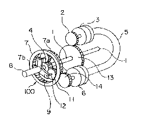
In Fig. 1 that illustrates a first embodiment of the
present invention, a reference numeral 1 denotes an input
shaft, a reference numeral 100 denotes a differential
epicycle reduction gear device, and a reference numeral 8
denotes an output shaft. A reference numeral 4 denotes a sun
gear of the epicycle reduction gear device that has been
-13-
2198582
secured to an end portion of the input shaft 1, a reference
numeral 7 denotes a ring gear of the epicycle reduction gear
device 100, a reference numeral 9 denotes carriers of the
epicycle reduction gear device 100 that have been fixed to
the output shaft 8, a reference numeral 12 denotes a
plurality (three in this embodiment) of planet shafts that
are fixed to the carriers 9 at equal intervals taken in the
circumferential direction of the epicycle reduction gear
device 100, and a reference numeral 11 denotes planetary
gears whose shafts are supported by the planet shafts 12
respectively and which are meshed with external teeth of the
sun gear 4 and internal teeth of the ring gear 7.
A reference numeral 3 denotes a variable amount of
discharge type hydraulic pump and a reference numeral 6
denotes a variable speed and reversible rotation type
hydraulic motor that is driven by a pressure oil that is
forcedly supplied from the hydraulic pump 3 through an oil
pipe 5. To the input shaft 1 there is secured an input shaft
gear 13 which is meshed with a pump driving gear 2 that is
fixed to an input shaft of the hydraulic pump 3, whereby the
hydraulic pump is driven by the torque of the input shaft 1.
A reference numeral 14 denotes an input gear that has
been fixed to the output shaft of the hydraulic motor 6. The
input gear 14 is meshed with external teeth 7a of the ring
gear 7 of the epicycle reduction gear device 100. As a
-14-
21985~2
result, the epicycle reduction gear device 100 is equipped
with two input systems, one of which is a first input system
having its torque input from the input shaft 1 to the sun
gear 4 and the other of which is a second input system having
its torque input from the input gear 14 of the hydraulic
motor 6 to the ring gear 7.
The operation of the variable speed power transmission
apparatus that has been constructed as mentioned above will
now be explained.
The torque of the input shaft is transmitted to the
variable amount of discharge type hydraulic pump 3 through
the input shaft gear 13 and pump driving gear 2 to thereby
drive the hydraulic pump 3. The pressure oil that has been
discharged from the hydraulic pump 3 is supplied to the
hydraulic motor 6 by way of the oil pipe 5, whereby the
hydraulic motor 6 is driven for rotation. In the driving
system having the hydraulic pump 3 and hydraulic motor 6 used
in combination, when the amount of discharge of the hydraulic
pump 3 is varied through electric control or manually, the
number of rotations of the hydraulic motor 6 is varied and,
since this hydraulic motor 6 is reversible, the rotation
direction thereof also is varied. Accordingly, it results
that the rotational force or torque of this hydraulic motor
6 is input to the ring gear 7 through the input gear 14.
Whereby, the ring gear 7 is forward rotated, reverse rotated
-15-
219~582
or stopped (made stationary).
On the other hand, the torque of the input shaft 1 is
input to the sum gear 4 of the epicycle reduction gear device
100 and is transmitted from this sun gear 4 to the output
shaft 8 through the planetary gears 11 each making its
rotation around the sun gear 4 while making its rotation
about its own axis between the sun gear 4 and internal teeth
7b of the ring gear 7 and then through the carriers 9.
In the power transmission system illustrated in Fig. 1,
when the hydraulic pump 3 is stopped, the hydraulic motor
also is stopped, whereby the rotation of the ring gear 7 is
stopped through the input gear 14 and as a result the ring
gear 7 is brought to a state of its being made stationary.
In this case, the rotation of the input shaft 1 is
transmitted to the output shaft 8 through the sun gear 4,
planet gears 11 and carriers 9 that are combined with each
other into an ordinary epicycle reduction gear device form by
having its speed reduced to a number of rotations that is
determined according to the teeth numbers of the respective
gears.
Also, when the ring gear 7 is caused to make a rotation
that is reverse from that of the output shaft 8 by the
hydraulic motor 6, the rotations number that is transmitted
from the carriers 9 to the output shaft 8 is more decreased
than the rotations number which when the ring gear 7 is in a
-16-
2198582
state of its being stopped (made stationary) is transmitted
thereto. Further, when the ring gear 7 is rotated in the
same direction as that of the output shaft 8 by the hydraulic
motor 6, conversely to the above the rotations number of the
output shaft 8 is increased and hence the speed thereof is
more increased than that which is when the ring gear is kept
stationary.
In the first embodiment illustrated in Fig. 1, when the
rotations number of the input shaft 1 is changed and it is
wanted to restore the rotations number of the output shaft 8
to a target rotations number, it is arranged to change the
amount of discharge of the hydraulic pump 3, to thereby cause
the forward rotation, stoppage or reverse rotation of the
hydraulic motor 6, to thereby cause the forward rotation,
stoppage or reverse rotation of the ring gear 7, and to
thereby cause the restoration and maintenance of the rotation
of each of the carriers 9 and output shaft 8 to and at the
target rotations number.
In this first embodiment, as mentioned above, by
controlling the state of discharge of the hydraulic pump 3
and thereby causing the forward rotation, stoppage or reverse
rotation of the hydraulic pump 6 and thereby causing a change
in the forward or reverse rotations number, or stoppage, of
the ring gear 7 of the differential epicycle reduction gear
device 100, it is possible to cause non-step change in the
-17-
2198582
rotations number of the output shaft 8.
In a second embodiment of the present invention that is
illustrated in Figs. 2 to 4, on an outer periphery of the
ring gear 7 there is mounted a brake 10 for braking this ring
gear 7 and, on the other hand, as illustrated in Fig. 4, a
clutch 12 is interposed between the pump driving gear 2 and
the hydraulic pump 3. The type of this brake 10 includes a
disk brake system wherein, as illustrated in Fig. 3(A), a
disk 7c whose diameter has been increased by the quantity
needed to brake the rotation of the ring gear 7 is provided
on one side (e.g., output shaft side) of this ring gear 7 and
this disk 7c is clamped for brake, a disk brake system
wherein, as illustrated in Fig. 3(B), the ring gear 7 is
clamped from both sides thereof by means of pads, etc. The
remaining construction of this second embodiment is the same
as that of the first embodiment and therefore the same
members or components are denoted by the same reference
symbols.
In Figs. 2 to 4, during an ordinary operation in which
the output rotations number is made variable, the brake 10 is
released to thereby perform the same operation as in the case
of the first embodiment. In this case, the clutch 12 is made
"on . When the hydraulic pump 3 or hydraulic motor 6 has
malfunctioned, or leakage of the pressure oil has occurred in
the oil pipe 5 system, with the result that the adjustment of
-18-
2198582
the rotations number of the ring gear 7 by the hydraulic
motor 6 has become disabled from being made, the brake 10 is
made 'on" to thereby make the ring gear 7 stationary. As a
result, the ring gear 7 is made stationary, whereby the
rotation of the input shaft 1 is made to have its rotations
number decreased down to a fixed rotations number by the
planetary gear 11 and carriers 9 and this speed reduced
rotation thereof is transmitted to the output shaft 8.
It is to be noted that during an operation in which the
ring gear 7 has been made stationary due to the malfunction
or the like of the hydraulic system, the clutch 12 is made
"off" to thereby interrupt the transmission of the torque
from the pump driving gear 2 to the hydraulic pump 3 and
thereby stop the operation of the hydraulic system.
Also, during a normal operation of the hydraulic system,
when the rotations number of the input shaft 1 has changed
and it is wanted to maintain the rotations number of the
output shaft 8 to be at a fixed value, it is arranged to
release the brake 10 and make the clutch 12 "on" to thereby
adjust the rotation of the ring gear 7 and thereby rotate the
output shaft 8 with a fixed number of rotations.
In a third embodiment of the present invention that is
illustrated in Fig. 5, the variable amount of discharge type
hydraulic pump and the variable/reversible rotation type
hydraulic motor 6 are provided close to each other, or are
-19-
2198582
provided with their housings being coupled to each other and
integrated. Further, an oil passage that replaces the oil
pipe 5 (see Fig. 1) is provided within the pump 3 and motor
6. Further, it is arranged to input the torque to the
hydraulic pump 3 from an input shaft la that is separate from
the sun gear 4.
In this embodiment, the operation thereof is the same as
that in the first embodiment excepting that the torque to be
input to the hydraulic pump 3 is made inputtable thereto from
the independent input shaft la. And the amount of discharge
of the hydraulic pump 3 is electrically or manually
controlled.
According to this embodiment, since the hydraulic pump
3 and hydraulic motor 6 are structurally integrated with each
other, the use of the hydraulic piping that is exposed to the
outside becomes unnecessary. Further, the use of the
hydraulic-pump driving gear system becomes also unnecessary.
As a result, the entire structure of the apparatus becomes
simplified and miniaturized.
Also, since the input shaft la has been provided
independently from the input shaft 1 of the epicycle
reduction gear device 100, the rotations number of the
hydraulic pump 3 becomes controllable irrelevantly to and
independently of the epicycle reduction gear device 100.
Therefore, when the rotations number of the input shaft 1 has
-20-
2198582
changed and it is wanted to maintain the rotations number of
the output shaft 8 to be at a fixed target rotations number,
it is possible by adjusting the rotations number of the input
shaft la of the hydraulic pump 3 to easily set the rotations
number of the output shaft 8 to be at the target rotations
number.
In a fourth embodiment that is illustrated in Fig. 6, a
brake lO that can brake the rotation of the ring gear 7 and
that is similar to that which is illustrated in Fig. 3(A) or
3(B) is additionally provided on the variable speed power
transmission apparatus according to the third embodiment
illustrated in Fig. 5.
In the fourth embodiment, during an ordinary variable
speed operation, the brake 10 is released (made "off") and
the rotations number of the input shaft la of the hydraulic
pump 3 is changed to thereby perform the same operation as in
the case of the third embodiment illustrated in Fig. 5.
When an inconvenience such as malfunction has occurred
in the hydraulic system, the brake 10 is made "on" to thereby
make the ring gear 7 stationary and thereby operate the
output shaft 8 with a rotations number that has been
decreased in a prescribed speed ratio from the rotations
number of the input shaft 1.
Also, even when no such inconvenience has occurred in
the hydraulic system, in a case where the output shaft 8 is
-21-
2198582
operated with the rotations number thereof being set to be
fixed, the brake 10 is made "on" to thereby make the ring
gear 7 stationary and thereby operate the output shaft 8 with
a rotations number that has been decreased in a prescribed
speed ratio from the rotations number of the input shaft 1.
Further, when the rotations number of the input shaft 1
has changed and it is needed to maintain the rotations number
of the output shaft 8 to be at a fixed value, the brake 10 is
made "off" and the rotations number of the hydraulic-pump 3
side input shaft la is adjusted to thereby adjust the
rotations number and rotation direction of the ring gear 7
and thereby maintain the rotations number of the output shaft
8 to be at a fixed value.
In a fifth embodiment of the present invention that is
illustrated in Fig. 7, a worm mechanism 200 composed of a
worm 21 and a worm wheel 22 is interposed between the
hydraulic motor 6 and the ring gear 7 of the epicycle
reduction gear device 100 which are used in the first
embodiment illustrated in Fig. 1.
That is, in Fig. 7, a reference numeral 21 denotes the
worm that has been fixed to a worm shaft 61 that is connected
directly to an output end of the hydraulic motor 6, a
reference numeral 22 denotes a worm wheel that is meshed with
the worm 21, a reference numeral 221 denotes a wheel shaft
that has the worm wheel 22 fixed thereto, a reference numeral
-22-
2198582
141 denotes an input gear that is fixed to the wheel shaft
and meshed with the ring gear, and a reference numeral 31
denotes a power source. The remaining construction is the
same as in the case of the first embodiment illustrated in
Fig. 1 and therefore the illustration thereof is made with
the same members or components being denoted by the same
reference symbols.
In the fifth embodiment that is illustrated in Fig. 7,
the torque that is transmitted from the power source 31 is
transmitted from the input shaft 1 to the epicycle reduction
gear device 100 while, on the other hand, the hydraulic pump
3 is driven through the input shaft gear 13 and then through
the pump driving gear 2.
The pressure oil that is supplied from the hydraulic
pump 3 is supplied to the hydraulic motor 6 through the oil
pipe 5, whereby the hydraulic motor 6 is driven by this
pressure oil. The rotation of the hydraulic motor 6 has its
speed reduced by the worm 21 and the worm wheel 22 and this
speed reduced rotation is transmitted to the ring gear 7
through the input gear 141. The operation in which the ring
gear 7 is forward rotated, reverse rotated or stopped by the
control that is made of the rotations number of the hydraulic
motor 6 is the same as in the case of the first embodiment
illustrated in Fig. 1.
Also, when an overload has acted on the output shaft 8
-23-
2198582
side, this overload acts, through the epicycle reduction gear
device 100, on the worm mechanism 200 composed of the worm 22
and the worm wheel 21. In consequence, the overload is
undertaken by the worm mechanism 200 as a result of the
reverse rotation prevention action that results from the mesh
between the worm 22 and the worm wheel 21. In consequence,
it is impossible that an excessive torque that results from
this overload acts on the hydraulic motor 6 and its driving
system.
In a sixth embodiment that is illustrated in Fig. 8, the
ring gear 7 of the epicycle reduction gear device 100 is
connected to a hydraulic transmission that is driven by a
power source.
That is, in Fig. 8, a reference numeral 32 denotes a
mechanical transmission, a reference numeral 31 denotes the
power source and a reference numeral 33 denotes the hydraulic
transmission. Whereby, the drive force of one driving system
for driving the output shaft 310 of the power source 31 is
transmitted to the input shaft 1 of the epicycle reduction
gear device 100 through the mechanical transmission 32 while,
on the other hand, the drive force of the other driving
system that branches off from the output shaft 310 is
transmitted to the hydraulic transmission 33 through gears 35
and 34.
Also, the output end of the hydraulic transmission 33 is
-24-
21985~2
connected to the ring gear 7 through a gear 41.
In the sixth embodiment, the rotation direction,
rotations number, transmission torque, etc. of the hydraulic
transmission 33 are controlled by a controller device not
illustrated and, by the output torque that results from this
control, the ring gear 7 is forward rotated, reverse rotated
or stopped.
On the other hand, because of the torque of the input
shaft 1 being made changeable by the mechanical transmission
32, it results that the input shaft 1 and the ring gear 7 can
be controlled respectively by the mechanical transmission 32
and the hydraulic transmission 33. This enables the
operation of the variable speed power transmission apparatus
over a wide range of rotation control.
In a seventh embodiment of the present invention that is
illustrated in Fig. 9, the worm mechanism 200 composed of the
worm 21 and the worm wheel 23 that is the same as in the case
of the fifth embodiment illustrated in Fig. 7 is interposed
between the output end of the hydraulic transmission 33 and
the ring gear 7.
That is, in Fig. 9, the reference numeral 31 denotes the
power source, the reference numeral 32 denotes the mechanical
transmission, and the reference numeral 33 denotes the
hydraulic transmission. Whereby, the hydraulic transmission
33 is driven by the drive force that has been made to branch
-25-
2198582
off from the output shaft 310 through gears 35 and 34.
And, to the output end of the hydraulic transmission 33,
as in Fig. 7, there is connected the worm 21 of the worm
mechanism 200 in interlocking relation with it. With this
worm 21 there is meshed the worm wheel 22. Further, to this
worm wheel 22 there is connected the ring gear 7 of the
epicycle reduction gear device 100.
By making this construction, when the rotation of the
hydraulic transmission 33 is changed, the ring gear 7 is
forward rotated, reverse rotated or stopped interlockingly
therewith.
In this seventh embodiment, when an overload acts on the
output shaft 8 side, as in the case of the fifth embodiment
illustrated in Fig. 7 this overload is undertaken by the worm
mechanism 200. As a result of the reverse rotation
prevention action of this worm mechanism 200, an excessive
torque that results from this overload is prevented from
being transmitted to the hydraulic transmission 33.
It is to be noted that although in each of the above-
mentioned embodiments the hydraulic motor or hydraulic
transmission 33 has been connected to the ring gear 7, the
present invention is not limited thereto. This system may be
of any type if it is a reversible/variable rotation type
hydraulic driver system that is driven by the oil pressure.
-26-