Sélection de la langue

Search

Sommaire du brevet 2198832 

Énoncé de désistement de responsabilité concernant l'information provenant de tiers

Une partie des informations de ce site Web a été fournie par des sources externes. Le gouvernement du Canada n'assume aucune responsabilité concernant la précision, l'actualité ou la fiabilité des informations fournies par les sources externes. Les utilisateurs qui désirent employer cette information devraient consulter directement la source des informations. Le contenu fourni par les sources externes n'est pas assujetti aux exigences sur les langues officielles, la protection des renseignements personnels et l'accessibilité.

Disponibilité de l'Abrégé et des Revendications

L'apparition de différences dans le texte et l'image des Revendications et de l'Abrégé dépend du moment auquel le document est publié. Les textes des Revendications et de l'Abrégé sont affichés :

  • lorsque la demande peut être examinée par le public;
  • lorsque le brevet est émis (délivrance).
(12) Brevet: (11) CA 2198832
(54) Titre français: VIS A AUTO-FRAISAGE
(54) Titre anglais: SELF COUNTER-SINKING SCREW
Statut: Périmé
Données bibliographiques
(51) Classification internationale des brevets (CIB):
  • F16B 25/02 (2006.01)
  • F16B 35/06 (2006.01)
(72) Inventeurs :
  • WALTHER, ULI (Canada)
  • YU, CHAO - HSIN (MICHAEL) (Taïwan, Province de Chine)
(73) Titulaires :
  • WALTHER, ULI (Canada)
  • WALTHER, ULI (Canada)
  • WALTHER, MIRCO (Canada)
  • WALTHER, GERDA (Canada)
(71) Demandeurs :
  • WALTHER, ULI (Canada)
  • YU, CHAO - HSIN (MICHAEL) (Taïwan, Province de Chine)
(74) Agent: GOWLING WLG (CANADA) LLP
(74) Co-agent:
(45) Délivré: 2002-04-16
(22) Date de dépôt: 1997-02-28
(41) Mise à la disponibilité du public: 1997-09-27
Requête d'examen: 1999-07-20
Licence disponible: S.O.
(25) Langue des documents déposés: Anglais

Traité de coopération en matière de brevets (PCT): Non

(30) Données de priorité de la demande:
Numéro de la demande Pays / territoire Date
08/622,632 Etats-Unis d'Amérique 1996-03-27

Abrégés

Abrégé français

Vis à autofraisage comprenant une portion de tête conique inversée formée au niveau d'un couvercle avec une cavité adaptée pour loger une pointe d'un tournevis et doté d'un fond conique, ledit fond conique ayant une pluralité de retraits triangulaires chacun ayant un côté latéral s'étendant vers l'intérieur pour former un bord aigu et un espace pour recevoir des copeaux, une portion filetée, et une portion décroissante dotée d'un diamètre plus large connectée avec la portion de tête et un diamètre plus petit connecté avec la portion filetée, dans laquelle le bord aigu fait un fraisage sur une pièce de travail lorsque la tête de vis fraisée est tournée dans celui-ci.


Abrégé anglais

A self-countersinking screw including an inverted-conical head portion formed at a top with a cavity adapted to receive a tip of a screwdriver and having a conical bottom, said conical bottom having a plurality of triangular recesses each having a lateral side extending inwardly to form a sharp edge and a space for receiving chips, a threaded portion, and a tapered portion having a large diameter connected with the head portion and a small diameter connected with the threaded portion, whereby the sharp edge will make a countersink on a workpiece when the countersunk head screw is turned therein.

Revendications

Note : Les revendications sont présentées dans la langue officielle dans laquelle elles ont été soumises.


Claims
1. A self-countersinking screw having a body with a longitudinal axis, said
body comprising in combination:
(a) a head which includes screwdriver engaging means at a top face and
an underside having an inversely frusto-conical surface;
(b) a threaded stem portion integral with the head and comprising a thread
adapted to drive the screw into a workpiece when the threaded stem portion is
rotated about said axis in a predetermined direction;
(c) a plurality of generally triangular recesses on said underside, said
recesses having straight sides, each said recess being axially spaced from
said
stem and from said top face;
(d) each recess comprising from the standpoint of said predetermined
direction, a generally planar trailing wall forming a linear cutting edge
coincident
with said frusto-conical underside;
(e) each said recess further including:
(i) a leading wall which is generally planar and convergent with said
trailing wall in the direction along said underside and towards
the axis of the screw;
(ii) a generally planar upper boundary wall extending between upper
ends of said trailing wall and said leading wall in a
circumferential direction and disposed at a spacing from said
top along said frusto-conical surface; and
(iii) a flat, generally triangular bottom.
2. A self-countersinking screw having a body with a longitudinal axis, said
body comprising in combination:
(a) a head which includes screwdriver engaging means at a top face and
an underside having an inversely frusto-conical surface;
(b) a threaded stem portion integral with the head and comprising thread
adapted to drive the screw into a workpiece when the threaded stem is rotated
about said axis in a predetermined direction;


(c) a plurality of generally triangular recesses on said underside, each said
recess being axially spaced from said stem and from said top face;
(d) a tapered intermediate portion tapering in a direction away from the
head and disposed between said underside and said stem portion, said
intermediate portion including a large diameter section adjoining said
underside,
and a small diameter section adjoining said threaded stem portion;
(e) each said recess including:
(i) from the standpoint of said predetermined direction, a generally
planar trailing wall forming a linear cutting edge coincident
with said frusto-conical underside;
(ii) a leading wall which is generally planar and convergent with
said trailing wall in the direction along said underside and
towards the axis of the screw;
(iii) a generally planar upper boundary wall extending between
upper ends of said trailing wall and said leading wall in a
circumferential direction and disposed at an axial spacing
from said top along said frusto-conical surface; and
(iv) a flat, generally triangular bottom.

3. A self-countersinking screw having a body with a longitudinal axis, said
body comprising in combination:
(a) a head which includes screwdriver engaging means at a top face and
an underside having an inversely frusto-conical surface;
(b) a threaded stem portion integral with the head and comprising thread
adapted to drive the screw into a workpiece when the threaded stem is rotated
about its axis in a predetermined direction;
(c) a plurality of generally triangular recesses on said underside, each said
recess being axially spaced from said stem portion and from said top face;
(d) a tapered intermediate portion tapering in a direction away from the
head and disposed between said underside and said stem portion, said
intermediate portion including a large diameter section adjoining said
underside,
and a small diameter section


adjoining said threaded stem portion;
(e) each said recess including:
(i) from the standpoint of said predetermined direction, a generally
planar trailing wall forming a linear cutting edge coincident
with said frusto-conical underside;
(ii) a leading wall which is generally planar and convergent with
said trailing wall in the direction along said underside and
towards the axis of the screw;
(iii) a generally planar upper boundary wall extending between
upper ends of said trailing wall and said leading wall in a
circumferential direction and disposed at an axial spacing
from said top along said frusto-conical surface; and
(iv) a flat, generally triangular bottom;
(f) the upper boundary walls of each said recesses being all generally
coplanar with a single plane generally perpendicular to the axis of the screw
and
spaced from said top surface.
4. A self-countersinking screw having a body with a longitudinal axis, said
body comprising in combination:
(a) a head which includes screwdriver engaging means at a top face and
an underside having an inversely frusto-conical surface;
(b) a threaded stem portion integral with the head and comprising thread
adapted to drive the screw into a workpiece when the threaded stem is rotated
about said axis in a predetermined direction;
(c) a plurality of generally triangular recesses on said underside, each said
recess being axially spaced from said stem portion and from said top face;
(d) each said recess having a tapered intermediate portion tapering in a
direction away from the head and disposed between said underside and said
stem portion, said intermediate portion including a large diameter section
adjoining said underside, and
a small diameter section adjoining said threaded stem portion;
(e) each said recess including:


(i) from the standpoint of said predetermined direction, generally
planar trailing wall forming a linear cutting edge coincident
with said frusto-conical underside;
(ii) a leading wall which is generally planar and convergent with
said trailing wall in the direction along said underside and
towards the axis of the screw;
(iii) a generally planar upper boundary wall extending between
upper ends of said trailing wall and said leading wall in a
circumferential direction and disposed at an axial spacing
from said top along said frusto-conical surface; and
(iv) a flat, generally triangular bottom so arranged that the depth of
each said recess increases in the direction from said leading
wall to a corner between said trailing wall and said upper
boundary wall;
(f) the upper boundary walls of each said recesses being all generally
coplanar with a single plane generally perpendicular to the axis of the screw
and
spaced from said top surface.
5. A self-countersinking screw having a body with a longitudinal axis, said
body comprising in combination:
(a) a head which includes screwdriver engaging means at a top face and
an underside having an inversely frusto-conical surface;
(b) a threaded stem portion integral with the head and comprising a thread
adapted to drive the screw into a workpiece when the threaded stem portion is
rotated about said axis in a predetermined direction;
(c) a plurality of generally triangular recesses on said underside, said
recesses having straight sides, each said recess being axially spaced from
said
stem and from said top face;
(d) each recess comprising from the standpoint of said predetermined
direction, a generally planar trailing wall forming a cutting edge coincident
with
said frusto-conical underside;


(e) each said recess further including:
(i) a leading boundary which is convergent with said cutting edge
in the direction along said underside and towards the axis of
the screw;
(ii) a generally planar upper boundary wall extending between an
upper end of said trailing wall and an upper end of said
leading boundary in a circumferential direction and disposed
at a spacing from said top along said frusto-conical surface;
and
(iii) a flat, generally triangular bottom.
6. The screw of claim 5, further comprising a tapered intermediate portion
tapering in a direction away from the head and disposed between said underside
and said stem, said intermediate portion including a large diameter section
adjoining said underside, and a small diameter section adjoining said threaded
stem portion.
7. The screw as claimed in claim 5, wherein the upper boundary walls are
all generally coplanar with a single plane which is generally perpendicular to
the
axis of the screw and is spaced from said top surface.
8. The screw as claimed in claim 5, wherein the depth of each said recess
increases in the direction from said leading boundary to a corner between said
trailing wall and said upper boundary wall.
9. A self-countersinking screw having a body with a longitudinal axis, said
body comprising in combination:
(a) a head which includes screwdriver engaging means at a top face and
an underside having an inversely frusto-conical surface;
(b) a threaded stem portion integral with the head and comprising thread
adapted to drive the screw into a workpiece when the
threaded stem is rotated about said axis in a predetermined direction;


(c) a plurality of generally triangular recesses on said underside, each said
recess being axially spaced from said stem and from said top face;
(d) a tapered intermediate portion tapering in a direction away from the
head and disposed between said underside and said stem portion, said
intermediate portion including a large diameter section adjoining said
underside,
and a small diameter section adjoining said threaded stem portion;
(e) each said recess including:
(i) from the standpoint of said predetermined direction, a generally
planar trailing wall forming a linear cutting edge coincident
with said frusto-conical underside;
(ii) a leading boundary which is convergent with said cutting edge
in the direction along said underside and towards the axis of
the screw;
(iii) a generally planar upper boundary wall extending between an
upper end of said trailing wall and an upper end of said
leading boundary in a circumferential direction and disposed
at an axial spacing from said top along said frusto-conical
surface; and
(iv) a flat, generally triangular bottom.

10. A self-countersinking screw having a body with a longitudinal
axis, said body comprising in combination:
(a) a head which includes screwdriver engaging means at a top face and
an underside having an inversely frusto-conical surface;
(b) a threaded stem portion integral with the head and comprising thread
adapted to drive the screw into a workpiece when the threaded stem portion is
rotated about its axis in a predetermined direction;
(c) a plurality of generally triangular recesses on said underside, each said
recess being axially spaced from said stem portion and from said top face;
(d) a tapered intermediate portion tapering in a direction away from the
head and disposed between said underside and said stem portion, said


intermediate portion including a large diameter section adjoining said
underside,
and a small diameter section adjoining said threaded stem portion;
(e) each said recess including:
(i) from the standpoint of said predetermined direction, a generally
planar trailing wall forming a linear cutting edge coincident
with said frusto-conical underside;
(ii) a leading boundary which is convergent with said cutting edge
in the direction along said underside and towards the axis of
the screw;
(iii) a generally planar upper boundary wall extending between an
upper end of said trailing wall and an upper end of said
leading boundary in a circumferential direction and disposed
at an axial spacing from said top along said frusto-conical
surface; and
(iv) a flat, generally triangular bottom;
(f) the upper boundary walls of each said recesses being all generally
coplanar with a single plane generally perpendicular to the axis of the screw
and
spaced from said top surface.

11. A self-countersinking screw having a body with a longitudinal axis,
said body comprising in combination:
(a) a head which includes screwdriver engaging means at a top face and
an underside having an inversely frusto-conical surface;
(b) a threaded stem portion integral with the head and comprising thread
adapted to drive the screw into a workpiece when the threaded stem is rotated
about said axis in a predetermined direction;
(c) a plurality of generally triangular recesses on said underside, each said
recess being axially spaced from said stem portion and from said top face;
(d) each said recess having a tapered intermediate portion tapering in a
direction away from the head and disposed between said underside and said
stem portion, said intermediate portion including a large diameter section


adjoining said underside, and a small diameter section adjoining said threaded
stem portion;
(e) each said recess including:
(i) from the standpoint of said predetermined direction, a generally
planar trailing wall forming a linear cutting edge coincident
with said frusto-conical underside;
(ii) a leading boundary which is convergent with said cutting edge
in the direction along said underside and towards the axis of
the screw;
(iii) a generally planar upper boundary wall extending between an
upper end of said trailing wall and said leading boundary in
a circumferential direction and disposed at an axial spacing
from said top along said frusto-conical surface; and
(iv) a flat, generally triangular bottom so arranged that the depth of
said recess increases in the direction from said leading
boundary to a corner between said trailing wall and said
upper boundary wall;
(f) the upper boundary walls of each said recesses being all generally
coplanar with a single plane generally perpendicular to the axis of the screw
and
spaced from said top surface.

12. A self-countersinking screw having a body with a longitudinal axis, said
body comprising in combination:
(a) a head which includes screwdriver engaging means at a top face and
an underside having an inversely frusto-conical surface;
(b) a threaded stem portion integral with the head and comprising a thread
adapted to drive the screw into a workpiece when the threaded stem portion is
rotated about said axis in a predetermined direction;
(c) a plurality of generally triangular recesses on said underside, said
recesses having straight sides, each said recess being axially spaced from
said
stem and from said top face;


(d) each recess comprising from the standpoint of said predetermined
direction, a generally planar trailing wall forming a linear cutting edge
coincident
with said frusto-conical underside;
(e) each said recess further including:
(i) a leading boundary which is convergent with said cutting edge
in the direction along said underside and towards the axis of
the screw;
(ii) a generally planar upper boundary wall extending between an
upper end of said trailing wall and an upper end of said
leading boundary in a circumferential direction and disposed
at a spacing from said top along said frusto-conical surface;
and
(iii) a flat, generally triangular bottom.

Description

Note : Les descriptions sont présentées dans la langue officielle dans laquelle elles ont été soumises.


CA 02198832 2001-08-21
_2-
Background of the Invention
The invention relates to a self-counter sinking screw. Different kinds of
self counter-sinking screw are know from prior art.
It is known, e.g. from US Patent 5,203,657 INagoshi et al.) to provide
a self-tapping screw, where the generally conical undersurface of the head of
the screw is particularly configured to prevent the bulging up of a gypsum
board cover sheet. In one embodiment, the underside of the head is provided
with a series of equidistantly spaced apart spot facing projection which also
provide the burring action to make space for the inversely conical underside
of
the head. This arrangement may be useful with gypsum board panels or the like
material, where the material of the board is soft, has a relatively small
density
and is easily displaceable or compressible. It would be inoperative when the
screw would have to be used with hard finish panels such as melamine, where
the material cut from the panel cannot be removed toward the threaded portion
1 5 of the screw.
US Patent 5,199,839 (DeHaitre) discloses a self locking screw provided
at its underside with a number of flat self locking projections having an
arcuate
edge. The edge may be used in burring action to provide a part of the seat for
the underside of the screw head. However, since there is no provision for
effective disposal of the burrs, the arrangement is only suitable in
applications
where the workpiece is from material such as wood composite material, but not
with a hard, dense material.
US Patent 3,903,784 (Dekker) shows another self-countersinking
fastener head, where the cutter edges at the underside of the head are
arcuately curved. Each cutter edge defines a trailing end of a cutter recess.
The
volume of the recess decreases in the direction from the threaded stem to the
top of the head. This is disadvantageous from the standpoint, firstly, of the
manufacturing costs as a curved edge is relatively difficult to produce.
Secondly, the upwards diminishing volume of the cutter recess does not
provide sufficient space for the burrs from immediately adjacent areas of the
workpiece as most of the material in self-countersinking 'is removed at the
upper, larger diameter portion of the countersink.


CA 02198832 2001-08-21
-3-
US Patent 465,101 (Richards) shows an arrangement wherein knives or
blades are forged to project from the truncated cone of the underside of the
screw head. The edges of the knives project beyond the contour of the
truncated cone. Therefore, they take away more material than is required for
countersinking the seat for the underside of the screw, which weakens the
strength of the engagement between the head and the workpiece.
Summary of the Invention
It is an object of the present invention to provide an improved self
counter-sinking screw which would further advance the art by avoiding or at
least reducing the above drawbacks.
In general terms, the present invention provides a self-countersinking
screw comprising, in combination:
(a) a head including screwdriver engaging means and an inversely frusto-
conical underside;
(b) a threaded stem portion;
(c) said underside being provided with a plurality of generally triangular
recesses increasing in volume in the general direction from said
intermediate portion toward said top;
(d) each recess comprising - from the standpoint of rotation of the head
driving the screw in a workplace - a trailing wall forming a cutting edge
coincident with said frusto-conical underside.
Preferably, there is provided a tapered intermediate portion just under the
underside of the head of the screw. Each recess preferably comprises a leading
boundary which is convergent with said cutting edge in the direction along
said
underside and towards the axis of the screw. In accordance with another
preferred feature of the invention, each said recess further comprises a flat
upper boundary wall extending between upper ends of said trailing wall and
said linear boundary in a circumferential direction and disposed near said
top.
The bottom of each recess is preferably planar and slopes such as to increase


CA 02198832 2001-08-21
-4-
the depth of the recess in a direction toward the corner between the upper
boundary wall and the trailing wall.
Brief Description of the Drawings
The invention will be described by way of a preferred embodiment, with
reference to the accompanying simplified, diagrammatic, not-to-scale drawings,
wherein:
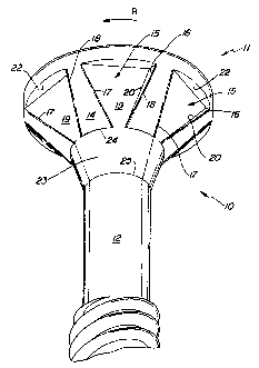
Figure 1 is a perspective view of the upper part of a screw
incorporating the features of the present invention;
Figure 2 is a front or side view of the upper part of the screw shown
in Fig. 1;
Figure 3 is section III-III of Fig. 2;
Figure 4 is section IV-IV of Fig. 2;
Figure 5 is a cross-sectional view showing the screw of the present
invention partly threaded in a workpiece; and
Figure 6 is a view similar to that of Fig. 5 but showing the screw
fully threaded in a workpiece.
Detailed Description of a Preferred Embodiment
With reference to the drawings and in particular to FIGS. 1, 2 and 3 thereof,
the self-countersinking screw 10 comprises a head 11 and a threaded stem
portion 12. The head 1 1 has the general shape of an inverted-conical member
and is formed, at the top, with screwdriver engaging means, in the embodiment
shown, a hexagonal recess 13 adapted to receive the tip of a screwdriver (not
shown). However, it should be noted that the screwdriver engaging means may
be of any other suitable shape. The head exhibits an inversely frusto-conical
underside 14 on which there are a plurality of generally triangular recesses
15.
The term "generally" triangular is used to indicate that the contour is not
a true triangle as will be apparent from the description which follows. Each
recess 15 comprises, from the standpoint of the direction of rotation R (Figs.


CA 02198832 2001-08-21
-5-
1, 3, 4) driving the screw in a workpiece, a trailing wall 16 and a leading
boundary 17. The trailing wall 16 forms a cutting edge 18 at the merger of the
trailing wall 16 with the surface of the underside 14.
In the embodiment shown, the leading boundary 17 is an obtuse angled
corner between a flat, planar bottom wall 19 and the underside 14. The
bottom wall 19 merges, at the trailing end of the recess 15, with a bottom
corner 20 where the bottom wall 19 adjoins the trailing wall 16. As shown, for
instance, in Fig. 1, the trailing wall 16 increases in height in the direction
towards the periphery of the head 1 1. In other words, the inclination of the
bottom wall 19 is such that the depth of the recess 15 and thus its volume is
at a maximum at the part near the periphery of the top of the head 1 1 .
The preferred embodiment shown in the drawings has both the leading
boundary 17 and the trailing wall 16 convergent toward the axis 21 (Fig. 2) of
the screw 10. The leading boundary 17 and the cutting edge 18 are preferably
1 5 straight and do not actually meet at their lower ends, where they are
closest
to the axis 21. The overall contour of the recess 15 can nevertheless be
referred to as being "generally" triangular.
The "generally triangular" contour of each recess 15 is enclosed by a
generally planar upper boundary wall 22 which extends between upper ends of
the trailing wall 16 and of the leading boundary 17 in a circumferential
direction
and is generally parallel with the top of the head 1 1. Thus, the wall 22
appears
linear in a side view (Fig. 2). The walls 22 of all recesses 15 are coplanar
with
one another as can be seen from Fig. 1 and are perpendicular to the axis 21 of
the screw.
Fig. 4 shows the radial width of the upper boundary wall 22, merges
with the obtuse angled edge of the leading boundary 17, and has a zero width
there. On the contrary, at the trailing wall 16, the radial width of the
boundary
wall 22 is higher due to the inclination of the bottom wall 19. Thus, it can
be
seen that the bottom wall 19 slopes into the respective cutout 15 from the


CA 02198832 2001-08-21
-6-
leading boundary 17 to the corner between the trailing wall 16 and the
boundary wall 22. This, together with the widening of the recess 15 in the
outward direction, is the preferred way of providing an increase in the volume
of each cutout in the direction along the underside 14 and away from the axis
21. The depth of the recess 15 is at a maximum at the corner of the walls 22
and 16.
A tapered intermediate portion 23 is formed between the head 1 1 and
the threaded stem 12. It includes a large diameter section 24 merging with the
head 1 1 and small diameter section 25 merging with the threaded portion 12.
In operation, (Figs. 5 and 6), the screw is threaded into a workpiece
which is typically made of wood laminated with a MelamineT"" or the like
surface finish sheet. The intermediate portion has a small included angle of
the
frustoconical face. Thus, when the screw is driven into a workpiece, the
frustoconical face is drawn into a passage previously made by the stem of the
screw. Eventually, the underside 14 having a relatively large included angle,
reaches the surface of the workpiece and as it is pressed against the bore
left
after the cutting edges 18 of the recesses 15, cut or burr a conical
countersink
in the workpiece. Since the cutting edges 18 are coincident with the
frustoconical surface of the underside, the countersink corresponds exactly to
the taper of the underside thus providing a firm and accurate engagement
between the head of the screw and the countersink in the workpiece. The
plurality of co-planar upper boundary walls 22 further reinforces the firm
hold
of the screw in the workpiece by blocking axial displacement of the screw
beyond a certain limit. The gradually increasing depth of the recesses 15
accommodates chips developed by the countersinking thus permitting firm
engagement of the underside surface 14 with the countersink. The overall
structure of the head is simpler than in known prior art and is thus less
expensive to produce.
Those skilled in the art will readily appreciate that many modifications
may exist of the preferred embodiment described without departing from the


CA 02198832 2001-08-21
_7_
scope of the present invention. The upper part of the underside of the head
may be modified to provide an outwardly projecting flange. The cutting edge
may be curved even though a straight edge is preferred from the standpoint of
manufacturing costs. The leading boundary 17, instead of being an obtuse
angled joinder, may have the shape of an edge of a leading wall. These are but
a few of examples of many modifications within the scope of the present
invention.
Therefore, I wish to protect by Letters Patent which may issue on this
application all such embodiments as fairly fall within the scope of my
contribution to the art.

Dessin représentatif
Une figure unique qui représente un dessin illustrant l'invention.
États administratifs

Pour une meilleure compréhension de l'état de la demande ou brevet qui figure sur cette page, la rubrique Mise en garde , et les descriptions de Brevet , États administratifs , Taxes périodiques et Historique des paiements devraient être consultées.

États administratifs

Titre Date
Date de délivrance prévu 2002-04-16
(22) Dépôt 1997-02-28
(41) Mise à la disponibilité du public 1997-09-27
Requête d'examen 1999-07-20
(45) Délivré 2002-04-16
Expiré 2017-02-28

Historique d'abandonnement

Il n'y a pas d'historique d'abandonnement

Historique des paiements

Type de taxes Anniversaire Échéance Montant payé Date payée
Le dépôt d'une demande de brevet 150,00 $ 1997-02-28
Taxe de maintien en état - Demande - nouvelle loi 2 1999-03-01 50,00 $ 1998-12-02
Requête d'examen 200,00 $ 1999-07-20
Taxe de maintien en état - Demande - nouvelle loi 3 2000-02-28 50,00 $ 2000-01-27
Taxe de maintien en état - Demande - nouvelle loi 4 2001-02-28 50,00 $ 2001-01-29
Taxe finale 150,00 $ 2001-12-19
Taxe de maintien en état - Demande - nouvelle loi 5 2002-02-28 75,00 $ 2002-01-28
Taxe de maintien en état - brevet - nouvelle loi 6 2003-02-28 75,00 $ 2003-02-04
Taxe de maintien en état - brevet - nouvelle loi 7 2004-03-01 75,00 $ 2003-11-06
Taxe de maintien en état - brevet - nouvelle loi 8 2005-02-28 100,00 $ 2005-01-28
Paiement des arriérés de taxes 100,00 $ 2006-02-17
Taxe de maintien en état - brevet - nouvelle loi 9 2006-02-28 100,00 $ 2006-02-17
Taxe de maintien en état - brevet - nouvelle loi 10 2007-02-28 125,00 $ 2007-02-27
Taxe de maintien en état - brevet - nouvelle loi 11 2008-02-28 250,00 $ 2008-01-28
Taxe de maintien en état - brevet - nouvelle loi 12 2009-03-02 250,00 $ 2009-01-28
Taxe de maintien en état - brevet - nouvelle loi 13 2010-03-01 250,00 $ 2010-02-01
Taxe de maintien en état - brevet - nouvelle loi 14 2011-02-28 250,00 $ 2011-01-28
Enregistrement de documents 100,00 $ 2011-04-05
Taxe de maintien en état - brevet - nouvelle loi 15 2012-02-28 450,00 $ 2012-01-30
Taxe de maintien en état - brevet - nouvelle loi 16 2013-02-28 450,00 $ 2013-01-30
Taxe de maintien en état - brevet - nouvelle loi 17 2014-02-28 450,00 $ 2014-02-24
Taxe de maintien en état - brevet - nouvelle loi 18 2015-03-02 450,00 $ 2015-02-23
Taxe de maintien en état - brevet - nouvelle loi 19 2016-02-29 450,00 $ 2016-02-22
Titulaires au dossier

Les titulaires actuels et antérieures au dossier sont affichés en ordre alphabétique.

Titulaires actuels au dossier
WALTHER, ULI
WALTHER, ULI
WALTHER, MIRCO
WALTHER, GERDA
Titulaires antérieures au dossier
YU, CHAO - HSIN (MICHAEL)
Les propriétaires antérieurs qui ne figurent pas dans la liste des « Propriétaires au dossier » apparaîtront dans d'autres documents au dossier.
Documents

Pour visionner les fichiers sélectionnés, entrer le code reCAPTCHA :


Pour visualiser une image, cliquer sur un lien dans la colonne description du document. Pour télécharger l'image (les images), cliquer l'une ou plusieurs cases à cocher dans la première colonne et ensuite cliquer sur le bouton "Télécharger sélection en format PDF (archive Zip)" ou le bouton "Télécharger sélection (en un fichier PDF fusionné)".

Liste des documents de brevet publiés et non publiés sur la BDBC .

Si vous avez des difficultés à accéder au contenu, veuillez communiquer avec le Centre de services à la clientèle au 1-866-997-1936, ou envoyer un courriel au Centre de service à la clientèle de l'OPIC.


Description du
Document 
Date
(yyyy-mm-dd) 
Nombre de pages   Taille de l'image (Ko) 
Description 2001-08-21 6 257
Dessins représentatifs 2002-03-12 1 10
Revendications 2001-08-21 9 373
Abrégé 2001-08-21 1 17
Abrégé 1997-02-28 1 15
Description 1997-02-28 6 234
Revendications 1997-02-28 4 159
Dessins 1997-02-28 3 77
Revendications 1999-07-20 4 170
Page couverture 1997-10-28 1 41
Page couverture 2002-03-12 1 37
Dessins représentatifs 1997-10-28 1 6
Poursuite-Amendment 2001-04-23 2 57
Taxes 2003-02-04 1 34
Taxes 2003-11-06 1 31
Taxes 2002-01-28 1 28
Cession 1997-02-28 3 115
Poursuite-Amendment 2001-08-21 18 710
Correspondance 2001-12-19 1 35
Poursuite-Amendment 1999-07-20 6 265
Taxes 2000-01-27 1 31
Taxes 1998-12-02 1 33
Taxes 2001-01-29 1 27
Taxes 2005-01-28 1 29
Taxes 2006-02-17 1 33
Taxes 2007-02-27 1 29
Taxes 2008-01-28 1 30
Taxes 2009-01-28 1 30
Taxes 2010-02-01 1 35
Cession 2011-04-05 4 101