Sélection de la langue

Search

Sommaire du brevet 2198953 

Énoncé de désistement de responsabilité concernant l'information provenant de tiers

Une partie des informations de ce site Web a été fournie par des sources externes. Le gouvernement du Canada n'assume aucune responsabilité concernant la précision, l'actualité ou la fiabilité des informations fournies par les sources externes. Les utilisateurs qui désirent employer cette information devraient consulter directement la source des informations. Le contenu fourni par les sources externes n'est pas assujetti aux exigences sur les langues officielles, la protection des renseignements personnels et l'accessibilité.

Disponibilité de l'Abrégé et des Revendications

L'apparition de différences dans le texte et l'image des Revendications et de l'Abrégé dépend du moment auquel le document est publié. Les textes des Revendications et de l'Abrégé sont affichés :

  • lorsque la demande peut être examinée par le public;
  • lorsque le brevet est émis (délivrance).
(12) Brevet: (11) CA 2198953
(54) Titre français: PIECE DE LIAISON DESAXEE DE FLECHE RELEVABLE
(54) Titre anglais: OFFSETTING LINK ASSEMBLY FOR FOLDING LUFFING JIB
Statut: Périmé et au-delà du délai pour l’annulation
Données bibliographiques
(51) Classification internationale des brevets (CIB):
  • B66C 23/04 (2006.01)
  • B66C 23/34 (2006.01)
(72) Inventeurs :
  • WANEK, MICHAEL J. (Etats-Unis d'Amérique)
  • WALKER, ROBERT J. (Etats-Unis d'Amérique)
  • KRAJNIK, DANIEL L. (Etats-Unis d'Amérique)
(73) Titulaires :
  • MANITOWOC CRANE GROUP, INC.
(71) Demandeurs :
  • MANITOWOC CRANE GROUP, INC. (Etats-Unis d'Amérique)
(74) Agent: CASSAN MACLEAN
(74) Co-agent:
(45) Délivré: 2000-10-10
(22) Date de dépôt: 1997-03-03
(41) Mise à la disponibilité du public: 1997-09-04
Requête d'examen: 1997-03-03
Licence disponible: S.O.
Cédé au domaine public: S.O.
(25) Langue des documents déposés: Anglais

Traité de coopération en matière de brevets (PCT): Non

(30) Données de priorité de la demande:
Numéro de la demande Pays / territoire Date
08/609,059 (Etats-Unis d'Amérique) 1996-03-04

Abrégés

Abrégé anglais


A crane boom and luffing jib assembly have an offsetting link to allow the
luffing
jib to fold back and under the main boom for assembly of the boom and luffing
jib
assembly on a construction site where the entire length of the boom and
luffing jib cannot
be laid out during assembly. A method of assembling the crane boom and luffing
jib
comprises the steps of assembling the luffing jib and boom, the luffing jib
pivotally
attached to the jib connection pivot, the luffing jib folded back and under
the boom along
a ground surface, the hinged connection allowing neutral axis of the jib boom
section to
be offset relative to the boom connection pivot; attaching the boom to a
crane; raising the
boom top upwardly, allowing the jib top to travel along the ground surface
until the
luffing jib is lifted off the ground surface; causing the jib boom section to
be aligned with
the jib connection pivot; and inserting hinge pins into the hinged connection
to lock the
jib boom section in axial alignment with the jib connection pivot, wherein the
luffing jib
is initially folded back and under the crane boom.

Revendications

Note : Les revendications sont présentées dans la langue officielle dans laquelle elles ont été soumises.


-8-
We claim:
1. A crane boom and luffing jib assembly, comprising:
(a) a crane boom having a boom top and a longitudinal neutral axis;
(b) a luffing jib having a jib butt section pivotally secured to the boom
top about a jib connection pivot, a jib boom section secured to the jib butt
section, the jib boom section having a longitudinal neutral axis; and
(c) an offsetting link structure connecting the jib boom section to the jib
butt section such that, when the luffing jib is in a folded set-up
configuration, the jib connection pivot is offset relative to the longitudinal
neutral axis of the jib boom section and the luffing jib is folded back and
under the crane boom.
2. A crane boom and luffing jib assembly, comprising:
(a) a crane boom having a boom top;
(b) a luffing jib, comprising a jib butt section pivotally secured to the
boom top, a jib boom section secured to the jib butt section, and a jib top
section secured to the jib boom section, each jib section having a
longitudinal neutral axis and each jib section having upper and lower
chords, in relation to a ground surface when the crane boom is raised and
the luffing jib is extended parallel to the ground surface; and
(d) a unitary offsetting link structure connecting the jib boom section to
the jib butt section, such that when the luffing jib is in a folded set-up
configuration, the longitudinal neutral axis of the jib boom section is offset
relative to the longitudinal neutral axis of the jib butt section.
3. The crane boom and luffing jib assembly of claim 2, wherein
the jib top section has a wheel at an outermost end.
4. The crane boom and folding luffing jib assembly of claim 2,
wherein the offsetting link comprises:

-9-
(a) a pair of side brackets connected by cross braces;
(b) each side bracket comprising a pair of plates spaced apart from
each other to form a channel to receive the ends of the lower chords of the
jib sections between lower ends of the respective pairs of plates and joined
to the offsetting link by an axle pin extending through aligned holes in the
plates and the ends of the chords, and the upper chords of the jib sections
received between upper ends of the respective pairs of plates, the upper
chords of the jib butt section connected to an upper end of the offsetting
link by hinge pins extending through aligned holes in the plates and an end
of the jib butt section upper chords, and the upper chords of the jib boom
section connected to the upper end of the offsetting link by pins extending
through a second hole in the plates aligned with holes in an end of the
upper chords of the jib boom section.
5. The crane boom and luffing jib assembly of claim 4, further
comprising a stop lug between the upper ends of the plates to engage an
abutment member attached to an end of the upper chords of the jib butt section
to limit the degree of rotation about the axle pins when the hinge pins are
removed.
6. The crane boom and luffing jib assembly of claim 5 wherein
the hinge pins are removed by a pin pulley, comprising:
(a) a winch carrying a cable, the cable passing through a pulley located
between the upper ends of the pairs of plates;
(b) the cable attached to the hinge pins, such that taking up cable on
the winch causes the hinge pins to be removed from the holes in the
offsetting link, thereby allowing the jib boom section to rotate about the
axle pin.
7. An offsetting link for pivotally connecting two sections of a
luffing jib having upper and lower chords, comprising a pair of side brackets

-10-
connected by cross-braces to form a link, each side bracket comprising a pair
of
plates spaced to receive an end of a jib section chord therebetween, the
chords
being retained in the brackets by pins.
8. The offsetting link of claim 9, wherein:
(a) each side bracket has a single hole in a lower end of the bracket
aligned with holes in an end of the lower chords of the jib sections, and
axle pins extending through the holes in the side brackets and through
holes in the lower chords of the jib sections to secure the jib sections to
each other and to the offsetting link;
(b) each side bracket has two holes in an upper end of the bracket, one
of the holes aligned with holes in an end of the upper chords of each of the
jib sections;
(c) the upper chords of one jib section are secured to the offsetting link
by a hinge pin, the upper chords of the other boom section secured to the
offsetting link by a second pin; and
(d) a stop lug is positioned between the plates at the upper end of each
bracket to engage an abutment member on the end of the upper members
of one of the jib sections to limit the degree of offset allowable when the
hinge pins are removed.
9. A crane comprising:
(a) an upper works rotatably mounted upon a mobile lower works, the
upper works rotatable about a vertical swing axis;
(b) a boom having a longitudinal neutral axis and upper and lower
chords spaced outwardly from the boom longitudinal neutral axis to provide
buckling strength to the boom, and a luffing jib connection pivot near the
boom longitudinal neutral axis;
(c) a luffing jib pivotally connected to the boom at the luffing jib
connection pivot, the luffing jib also having a longitudinal neutral axis and
upper and lower chords spaced outwardly from the jib longitudinal neutral

-11-
axis to provide buckling strength to the jib, with the jib connection pivot
near the jib longitudinal neutral axis when the jib is in an operational
configuration;
(d) one of said boom or said jib including a hinge longitudinally spaced
from said luffing jib connection pivot to allow the longitudinal neutral axis
of
the boom or the jib to be offset relative to the jib connection pivot.
10. The crane of claim 9, wherein the hinge joins a jib butt section
to a jib boom section, allowing the longitudinal neutral axis of the jib to be
offset
relative to the jib connection pivot.
11. The crane of claim 9, further comprising at least one luffing jib
pendant and first and second masts for raising and lowering the luffing jib,
and a
luffing jib backstop assembly.
12. The crane of claim 9, wherein said hinge is part of an
offsetting link which comprises a pair of side brackets connected by cross-
braces,
each side bracket comprising a pair of parallel plates spiced to receive an
end of
the boom or jib chords therebetween, the chords retained in the brackets by
pins.
13. The crane of claim 12, the hinge further comprising a stop lug
positioned between the plates at an upper end of each bracket to engage an
abutment member on the end of the upper chords of the boom or the jib to limit
the degree of offset allowable when the pins are removed.
14. The crane of claim 10, wherein the hinge is part of an
offsetting link which comprises:
(a) a pair of side brackets connected by cross-braces, each side
bracket comprising a pair of parallel plates spaced to receive an end of an
upper or lower chord therebetween, the chords retained in the brackets by
pins;

-12-
(b) each side bracket having a single hole in a lower end of the bracket
aligned with holes in an end of the lower chords of the jib butt section and
jib boom section, and an axle pin extending through the holes in the side
brackets and through holes in the lower chords to secure the jib boom
section and the jib butt section to each other and to the offsetting link;
(c) each side bracket having two holes in an upper end of the bracket,
one of the holes aligned with holes in the ends of each of the upper chords
of the jib butt section, the jib butt section upper chords secured to the
offsetting link by a hinge pin, the other of the holes in the side brackets
aligned with holes in the upper chords of the jib boom section, the upper
chords of the jib boom section secured to the offsetting link by a pin; and
(d) a stop lug positioned between the plates at the upper end of each
bracket to engage an abutment member on the end of the upper chords of
the jib butt section to limit the degree of offset allowable when the hinge
pins are removed.
15. A crane boom and hinged luffing jib in a folded set-up
configuration, comprising:
(a) a crane boom having a neutral axis and a boom top;
(b) a luffing jib pivotally affixed to the boom top near the neutral axis,
the luffing jib folded back and under the boom along a ground surface in
the set-up configuration.
16. A method of assembling a crane boom and luffing jib, the
boom having a boom top, a longitudinal neutral axis and a jib connection pivot
on
the boom top, the luffing jib having a jib butt section, a jib boom section
having a
longitudinal neutral axis, a jib top section and a hinged connection
connecting the
jib butt section and jib boom section, comprising the steps of:
(a) assembling the luffing jib and boom, the luffing jib pivotally attached
to the jib connection pivot, the luffing jib folded back and under the boom

-13-
along a ground surface, the hinged connection allowing the neutral axis of
the jib boom section to be offset relative to the boom connection pivot;
(b) attaching the boom to a crane;
(c) raising the boom top upwardly, causing the jib top section to travel
along the ground surface until the luffing jib is lifted off the ground
surface;
(d) causing the neutral axis of the jib boom section to be aligned with
the jib connection pivot; and
(e) inserting pins into the hinged connection to lock the jib boom section
in axial alignment with the jib connection pivot.
17. The method of claim 16, wherein the jib top travels along the
ground surface on a wheel attached to the jib top.
18. The crane boom and luffing jib assembly of claim 1, wherein
the jib connection pivot is located near the boom neutral axis.
19. The method of claim 16 wherein the jib connection pivot is
located near the longitudinal neutral axis of the boom.

Description

Note : Les descriptions sont présentées dans la langue officielle dans laquelle elles ont été soumises.


CA 02198953 2000-07-20
-1-
FIELD OF THE INVENTION
This invention relates to lift-crane booms and luffing jibs, and more
particularly
to an offsetting link that allows the luffing jib to be folded under and along
the main
boom, thereby decreasing the area necessary for assembly of the crane at the
construction
site.
BACKGROUND OF THE INVENTION
Construction cranes having large main booms are often equipped with a luffmg
jib to allow the crane to reach further from its base when the construction
site is such that
the swing axis of the main boom is confined, as for example, when neighboring
structures obstruct the area through which the main boom can swing. A crane
equipped
with a luffing jib can raise its main boom at a steep angle relative to the
ground surface,
and then extend the luffing jib at a shallow angle relative to the ground
surface, thereby
increasing the crane's reach over such obstructions.
In many cases, the luffing jib may be well over half as long as the main boom,
and in some instances may be nearly as long as the main boom. Consequently, a
large
area is needed at the construction site to lay the boom and luffmg jib out
during
assembly, prior to raising the main boom. Given that the luffing jib design is
intended to
be used in confined construction sites, it is often impossible to lay out the
entire
combined length of the main boom and luffing jib. An alternative method of
assembling
2 0 the boom and luffing jib would be to fold the luffing jib under the main
boom. However,
the main boom has a much larger cross-sectional area than the luffmg jib, and
the luffing
jib does not fold directly under the main boom when the luffing jib connection
pivot, the
point of attachment of the luffing jib to the main boom, is on or near the
neutral axis of
the main boom, because the luffing jib would then contact the main boom near
the pivot
2 5 point.
Folding booms have been made with the pivot point moved laterally away from
the neutral axis of the boom sections to allow the folding section to clear
the main
section, as in U.S. Patent Nos. 2,529,454 issued November 7, 1950 to
Marcantonio, and
3,306,470, issued February 28, 1967 to Green, et al. Such an arrangement is
not possible
3 0 with a folding luffmg jib, however, because the pivot would have to moved
too far off
the neutral axis to allow the luffmg jib to clear the laxge main boom.

CA 02198953 2000-07-20
-2-
SUMMARY OF THE INVENTION
In one embodiment, this invention provides a crane boom and hinged luffing jib
having a folded set-up configuration, comprising:
(a) a crane boom having a neutral axis and a boom top; and
(b) a luffing jib pivotally affixed to the boom top near the neutral axis, the
luffmg
jib folded back and under the boom along a ground surface in the set-up
configuration.
In a preferred embodiment, the invention provides a crane boom and luffing jib
assembly, comprising:
(a) a crane boom having a boom top and a longitudinal neutral axis;
(b) a luffing jib having a jib butt section pivotally secured to the boom top
about a
jib connection pivot, a jib boom section secured to the jib butt section, the
jib
boom section having a longitudinal neutral axis; and
(c) an offsetting link structure connecting the j ib boom section to the j ib
butt
section such that the jib connection pivot may be offset relative to the
longitudinal neutral axis of the jib boom section to allow the luffing jib to
fold
back and under the crane boom.
A preferred embodiment of the offsetting link comprises a pair of side
brackets
connected by cross-braces to form a link of the same cross-sectional area as
the jib
2 0 sections to be joined, each side bracket comprising a pair of parallel
plates spaced to
receive an end of a jib section chord therebetween, the chords retained in the
brackets by
pins. Preferably, a stop lug is positioned between the plates at the upper end
of each
bracket to engage an abutment member on the end of the upper members of one of
the
boom sections to limit the degree of offset allowable when the hinge pins are
removed.
In a preferred embodiment, the crane boom and luffing jib assembly includes a
pin puller mechanism to remove the hinge pins, comprising:
(a) a winch carrying a cable, the cable passing through a pulley mechanism
located between the hinge pins;
(b) the cable attached to the hinge pins, such that taking up cable on the
winch
3 0 causes the hinge pins to be removed from the holes in the offsetting link,
thereby
allowing the jib boom section to rotate about the axle pin.

2~~-X953
-3-
In another preferred embodiment, the crane boom and luffing jib are
assembled by a method comprising the steps of
(a) assembling the luffing jib and boom, the luffing jib pivotally attached to
the jib
connection pivot, the luffing jib folded back and under the boom along a
ground
surface, the hinged connection allowing neutral axis of the jib boom section
to be
offset relative to the boom connection pivot;
(b) attaching the boom to a crane;
(c) raising the boom top upwardly, allowing the jib top to travel along the
ground
surface until the luffing jib is lifted off the ground surface;
(d) causing the jib boom section to be aligned with the jib connection pivot;
and
(e) inserting hinge pins into the hinged connection to lock the jib boom
section in
axial alignment with the jib connection pivot.
In another preferred embodiment, a crane comprises:
(a) an upper works rotatably mounted upon a mobile lower works, the upper
works rotatable about a vertical swing axis;
(b) a boom having a longitudinal neutral axis and upper and lower chords
spaced
outwardly from the boom longitudinal neutral axis to provide. buckling
strength to
the boom, and a luffmg jib connection pivot on or near the boom longitudinal
neutral axis;
(c) a luffing jib pivotally connected to the boom at the lufling jib
connection
pivot, the luffing jib, also having a longitudinal neutral axis and upper and
lower
chords spaced outwardly from the jib longitudinal neutral axis to provide
buckling
strength to the jib, with the jib connection pivot on or near the jib
longitudinal
~ neutral axis when the jib is in an operational configuration;
(d) one of said boom or said jib including a hinge longitudinally spaced from
said
luffing jib connection pivot to allow the longitudinal neutral axis of boom or
the jib
to be offset relative to the jib connection pivot.
This invention solves the problem of having the luffing jib connected to the
boom near the boom longitudinal neutral axis while allowing the luffing jib to
be
configured in a folded set-up position, under the main boom. By including an
offsetting
link, or hinge, within the lulling jib, the lulling jib is allowedto bend,
clearing the main
boom while keeping the pivot point close to the neutraLaxis of the boom
sections. The

CA 02198953 2000-07-20
-4-
other advantages of this invention, as well as the invention itself, will best
be understood
in view of the drawings, a brief description of which follows.
BRIEF DESCRIPTION OF THE DRAWINGS
FIG. 1 is a side view of a lift-crane equipped with a main boom and luffing
jib in an "out
front" layout position, prior to raising the boom. The dashed lines show the
operation of
raising the boom and luffing jib.
FIG. 2 is a side view of a lift crane equipped with a main boom and luffing
jib in the
"folded-under" set-up configuration enabled by the present invention.
FIG. 3 is an enlarged side view of the junction of the luffing jib butt
section and jib boom
section, connected by an offsetting link, in a coaxially-aligned orientation.
FIG 3A is a side view of the end of upper chord of the jib boom section
showing the
points of attachment to the offsetting link.
FIG. 4 is a side view of the junction of the luffing jib butt section and jib
boom section of
FIG. 3, connected by the offsetting link in an offset orientation.
FIG. 5 is a further enlarged side view of the offsetting link of FIG. 3.
FIG. 6 is a plan view of the offsetting link taken along line 6-6 of FIG. 5.
FIG. 7 is a top view of the offsetting link taken along line 7-7 of FIG. 5.
FIG. 8 is a plan view of a pin puller mechanism for use with the offsetting
link of FIG. 5.
DETAILED DESCRIPTION OF THE
2 0 DRAWINGS AND PREFERRED EMBODIMENTS
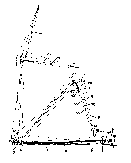
Fig. 1 depicts a lift crane 10 positioned prior to operational deployment in
an "out
front" layout position. The crane 10 has an upper works 12 pivotally mounted
on a lower
works 14, the upper works 12 rotatable on the lower works 14 about a vertical
swing
axis, and a boom 16 to which is pivotally attached a luffing jib 18 at a jib
connection
2 5 pivot 17, each of the boom 16 and luffmg jib 18 having a longitudinal
neutral axis 9, 11.
In the "out front" position depicted in Fig. 1, the luffmg jib 18 extends
directly outwardly
from the boom 16, and each of the sections of the luffing jib 18 and boom 16
are
coaxially aligned. The luffing jib 18 includes upper chords 22, lower chords
24 and
cross-braces 26, and may be equipped with a wheel 19 at the outermost end. The
terms
3 0 "upper" and "lower" chords are chosen with reference to the ground surface
7 when the

CA 02198953 1999-04-07
- $ -
boom 16 is in a raised position and the luffing jib 18 is extended, as shown
in the C
position of Fig. 1, and this convention is followed herein. When the luffing
jib is folded
under the boom, the lower chords 24 will be positioned adjacent the boom,
while the
upper chords 22 will be positioned adjacent the ground surface 7.
$ The operation of raising the boom 16 and luffing jib 18 from a set-up
position to an operational position is shown in Fig. 1. Although Fig. ,1
depicts the raising
operation from the "out front" configuration, indicated by position A, the
operation is
identical for raising the boom 16 and luffing jib 18 from the "folded-under"
configuration.
As the boom 16 is raised by boom hoist rigging 13, the outermost end of the
jib top
section 31 travels along the ground surface 7, until the jib top section 31 is
lifted off the
ground surface 7, after which the lung jib 18 reaches a point at which it is
suspended nearly
vertically from the boom 16. At this point, the weight of the luffing jib 18
may cause the
sections to align. However, it may be necessary to slightly tension the
lufflng
jib 18 to cause the sections to align. First and second masts 23, 2$ are
connected to the
boom 16 and luffing jib 18 respectively, and preferably, a lufflng jib
backstop assembly
may also be included, as disclosed in U.S. Patent No. 5,292,016. At least one
luff-lng jib
pendant 20 originates on a take-up mechanism on or near the crane upper works
12,
traverses the masts 23, 2$ and attaches near the outermost end of the luf~ng
jib 18.
Tensioning the luffing jib pendant 20 causes the masts 23, 25 to be brought
together, thereby
raising the luffing jib 18, as indicated by positions B, C and D of Fig. 1
Fig. 2 depicts the lift crane 10 positioned prior to operatioilal deployment
in
a folded set-up position. In the folded position depicted in Fig. 2., the
luffing jib 1.8 is
folded under the boom 16 and rests on a ground surface 7. The luffing jib 18
comprises a
2$ jib butt section 29, a jib boom section 30 and jib top section 31, having a
wheel 19
attached to the outermost end. The jib butt section 29 is pivotally attached
to the jib boom
section 30 by an offsetting link 32.
Fig. 3 is a detailed side view of the connection between the jib butt
section 29 and the jib boom section 30, with the jib sections 29, 30 in a
coaxially-aligned
orientation. Although only one side surface of the structure is shown, it is
to be
understood that the opposite side of the structure is identical. The jib butt
section 29
includes upper chords 41, lower chords 43 and cross braces 45, and the jib
boom section

CA 02198953 2000-07-20
-6-
includes upper and lower chords 51 and 53 respectively, and cross braces 55.
An
offsetting link 32 connects the jib butt section 29 to the jib boom section
30. The lower
chords 43 of the jib butt section 29 are connected to the lower chords 53 of
the jib boom
section 30 and the lower chords 43, 53 are connected to the offsetting link 32
by an axle
pin 48 that extends through aligned holes in the lower end 32a of the
offsetting link 32
and the lower chords 43, 53 of the jib sections 29, 30. The upper chords 41 of
the jib butt
section 29 are connected to the upper end 32b of the offsetting link 32 by
hinge pins 47.
The upper chords 51 of the jib boom section 30 are separately connected to the
upper end
32b of the offsetting link 32 by pins 49. It should be understood, however,
that the
offsetting link 32 is not used when the crane is in the operational position,
in that when
the jib butt section 29 and jib boom section 30 are in the aligned
configuration shown in
Fig. 3, compression is transferred from the jib boom section 30 to the jib
butt section 29,
not through the offsetting link 32.
Fig. 3A depicts the end of the upper chord 41 of the jib butt section 29,
illustrating the hole 69 aligned with hole 58 in the offsetting link 32 (shown
in Fig. 5) to
receive hinge pin 47, a notch 63 to contact pin 49 when the jib butt section
29 and jib
boom section 30 are in a coaxially-aligned orientation, and an abutment member
62.
Fig. 4 depicts the connection between the jib butt section 29 and the jib boom
section 30 with the jib sections 29, 30 in an axially-offset position. When
hinge pin 47 is
2 0 removed, the jib sections 29, 30 are allowed to pivot on axle pin 48 until
a stop lug 60 on
the offsetting link 32 contacts an abutment member 62 (FIG. 3A) on the end of
the upper
chords 41 of the jib butt section 29. Pin 49 remains in place to secure the
upper chords
51 of the jib boom section 30 to the offsetting link 32.
Fig. 5 depicts the offsetting link 32 in a plane parallel to the longitudinal
neutral
2 5 axis of the jib, while Fig. 6 depicts the offsetting link 32 in a plane
perpendicular to the
longitudinal neutral axis of the jib. Fig. 7 is a top view of the offsetting
link. The
offsetting link 32 includes side brackets 65, comprising side plates 66, 67,
spaced to form
a channel to receive the ends of the boom sections 29, 30, and joined by a
stop lug 60.
The lower ends 65a of the side brackets 65 each have a hole 61 to receive axle
pin 48.
3 0 The upper ends 65b of the side brackets 65 each have two holes 58, 59 to
receive hinge
pins 47 and pins 49 respectively. The side brackets 65 are joined by cross
braces 68.

CA 02198953 2000-07-20
Fig. 8 depicts a pin puller mechanism to allow the crane operator to remove
hinge
pins 47 while the boom and luffing jib are raised off the ground. A hand winch
(not
shown) carries a cable 70, which passes over a pulley mechanism 72, located
between
hinge pins 47. Although only one hinge pin 47 is shown, it is to be understood
that the
connections are the same for both hinge pins 47. Cable 70 is directed to both
hinge pins
47 and attached to each by means of a ring eye 74 mounted on the head thereof,
or by
other suitable means. Winding the cable 70 onto the winch causes the hinge
pins 47 to
be simultaneously retracted.
The crane boom and luffing jib are raised to an operational position as
follows, in
1 o reference to Figs. 1-5. With hinge pins 47 retracted, the top of boom 16
is raised
upwardly by the boom hoist rigging 13. The luffing jib 18 travels outwardly
from the
crane 10, rolling along the ground on the wheel 19 attached to the end of the
luffing jib
18, until the luffing jib 18 is approximately vertical. When the luffing jib
18 is
approximately vertical, hanging from the boom 16 its own weight pulls the jib
butt
section 29 and jib boom section 30 into coaxial alignment, and the hinge pins
47 are
replaced. Alternatively, it may be necessary to slightly tension the luffing
jib pendants 20
to swing the jib boom section into alignment. Thereafter, the luffmg jib 18 is
raised to its
operational position.
The foregoing described embodiments should be considered in all respects only
2 0 as illustrative and not restrictive, and the scope of the invention is,
therefore, to be
indicated by the appended claims rather than by the foregoing description. All
changes
which come within the meaning and range of equivalency of the claims are to be
embraced within their scope.

Dessin représentatif
Une figure unique qui représente un dessin illustrant l'invention.
États administratifs

2024-08-01 : Dans le cadre de la transition vers les Brevets de nouvelle génération (BNG), la base de données sur les brevets canadiens (BDBC) contient désormais un Historique d'événement plus détaillé, qui reproduit le Journal des événements de notre nouvelle solution interne.

Veuillez noter que les événements débutant par « Inactive : » se réfèrent à des événements qui ne sont plus utilisés dans notre nouvelle solution interne.

Pour une meilleure compréhension de l'état de la demande ou brevet qui figure sur cette page, la rubrique Mise en garde , et les descriptions de Brevet , Historique d'événement , Taxes périodiques et Historique des paiements devraient être consultées.

Historique d'événement

Description Date
Le délai pour l'annulation est expiré 2011-03-03
Lettre envoyée 2010-03-03
Inactive : CIB de MCD 2006-03-12
Accordé par délivrance 2000-10-10
Inactive : Page couverture publiée 2000-10-09
Inactive : Pages reçues à l'acceptation 2000-07-20
Préoctroi 2000-07-20
Inactive : Taxe finale reçue 2000-07-20
Un avis d'acceptation est envoyé 2000-01-21
Lettre envoyée 2000-01-21
month 2000-01-21
Un avis d'acceptation est envoyé 2000-01-21
Inactive : Approuvée aux fins d'acceptation (AFA) 1999-12-16
Modification reçue - modification volontaire 1999-08-30
Inactive : Dem. de l'examinateur par.30(2) Règles 1999-05-28
Modification reçue - modification volontaire 1999-04-07
Inactive : Dem. de l'examinateur par.30(2) Règles 1998-12-07
Modification reçue - modification volontaire 1998-02-19
Lettre envoyée 1998-02-18
Lettre envoyée 1998-02-17
Modification reçue - modification volontaire 1997-09-15
Inactive : Transfert individuel 1997-09-15
Demande publiée (accessible au public) 1997-09-04
Inactive : CIB en 1re position 1997-07-17
Inactive : CIB attribuée 1997-07-17
Inactive : Demandeur supprimé 1997-07-07
Inactive : Lettre de courtoisie - Preuve 1997-04-01
Exigences pour une requête d'examen - jugée conforme 1997-03-03
Toutes les exigences pour l'examen - jugée conforme 1997-03-03

Historique d'abandonnement

Il n'y a pas d'historique d'abandonnement

Taxes périodiques

Le dernier paiement a été reçu le 2000-03-03

Avis : Si le paiement en totalité n'a pas été reçu au plus tard à la date indiquée, une taxe supplémentaire peut être imposée, soit une des taxes suivantes :

  • taxe de rétablissement ;
  • taxe pour paiement en souffrance ; ou
  • taxe additionnelle pour le renversement d'une péremption réputée.

Les taxes sur les brevets sont ajustées au 1er janvier de chaque année. Les montants ci-dessus sont les montants actuels s'ils sont reçus au plus tard le 31 décembre de l'année en cours.
Veuillez vous référer à la page web des taxes sur les brevets de l'OPIC pour voir tous les montants actuels des taxes.

Titulaires au dossier

Les titulaires actuels et antérieures au dossier sont affichés en ordre alphabétique.

Titulaires actuels au dossier
MANITOWOC CRANE GROUP, INC.
Titulaires antérieures au dossier
DANIEL L. KRAJNIK
MICHAEL J. WANEK
ROBERT J. WALKER
Les propriétaires antérieurs qui ne figurent pas dans la liste des « Propriétaires au dossier » apparaîtront dans d'autres documents au dossier.
Documents

Pour visionner les fichiers sélectionnés, entrer le code reCAPTCHA :


Pour visualiser une image, cliquer sur un lien dans la colonne description du document (Temporairement non-disponible). Pour télécharger l'image (les images), cliquer l'une ou plusieurs cases à cocher dans la première colonne et ensuite cliquer sur le bouton "Télécharger sélection en format PDF (archive Zip)" ou le bouton "Télécharger sélection (en un fichier PDF fusionné)".

Liste des documents de brevet publiés et non publiés sur la BDBC .

Si vous avez des difficultés à accéder au contenu, veuillez communiquer avec le Centre de services à la clientèle au 1-866-997-1936, ou envoyer un courriel au Centre de service à la clientèle de l'OPIC.


Description du
Document 
Date
(yyyy-mm-dd) 
Nombre de pages   Taille de l'image (Ko) 
Description 1997-03-02 7 365
Abrégé 1997-03-02 1 26
Revendications 1997-03-02 6 237
Dessins 1997-03-02 4 107
Abrégé 2000-07-19 1 28
Description 2000-07-19 7 374
Dessin représentatif 1997-10-14 1 10
Dessin représentatif 2000-09-13 1 10
Page couverture 1997-10-14 2 77
Description 1999-04-06 7 368
Description 1999-08-29 7 367
Page couverture 2000-09-13 1 44
Dessins 1997-09-14 3 63
Dessins 1998-02-18 4 96
Revendications 1999-04-06 6 258
Description 2000-10-08 7 374
Courtoisie - Certificat d'enregistrement (document(s) connexe(s)) 1998-02-17 1 118
Courtoisie - Certificat d'enregistrement (document(s) connexe(s)) 1998-02-16 1 118
Rappel de taxe de maintien due 1998-11-03 1 110
Avis du commissaire - Demande jugée acceptable 2000-01-20 1 166
Avis concernant la taxe de maintien 2010-04-13 1 171
Correspondance 1997-03-31 1 23
Correspondance 2000-07-19 7 336
Taxes 2000-03-02 1 42
Correspondance 2000-01-20 1 88