Sélection de la langue

Search

Sommaire du brevet 2199085 

Énoncé de désistement de responsabilité concernant l'information provenant de tiers

Une partie des informations de ce site Web a été fournie par des sources externes. Le gouvernement du Canada n'assume aucune responsabilité concernant la précision, l'actualité ou la fiabilité des informations fournies par les sources externes. Les utilisateurs qui désirent employer cette information devraient consulter directement la source des informations. Le contenu fourni par les sources externes n'est pas assujetti aux exigences sur les langues officielles, la protection des renseignements personnels et l'accessibilité.

Disponibilité de l'Abrégé et des Revendications

L'apparition de différences dans le texte et l'image des Revendications et de l'Abrégé dépend du moment auquel le document est publié. Les textes des Revendications et de l'Abrégé sont affichés :

  • lorsque la demande peut être examinée par le public;
  • lorsque le brevet est émis (délivrance).
(12) Brevet: (11) CA 2199085
(54) Titre français: APPAREIL DE DISTILLATION
(54) Titre anglais: DISTILLATION APPARATUS
Statut: Périmé et au-delà du délai pour l’annulation
Données bibliographiques
(51) Classification internationale des brevets (CIB):
  • B01D 3/14 (2006.01)
  • F25J 3/04 (2006.01)
(72) Inventeurs :
  • TOPPEL, KARL O. (Etats-Unis d'Amérique)
(73) Titulaires :
  • THE BOC GROUP, INC.
(71) Demandeurs :
  • THE BOC GROUP, INC. (Etats-Unis d'Amérique)
(74) Agent: GOWLING WLG (CANADA) LLP
(74) Co-agent:
(45) Délivré: 2000-07-18
(22) Date de dépôt: 1997-03-04
(41) Mise à la disponibilité du public: 1997-10-30
Requête d'examen: 1997-03-04
Licence disponible: S.O.
Cédé au domaine public: S.O.
(25) Langue des documents déposés: Anglais

Traité de coopération en matière de brevets (PCT): Non

(30) Données de priorité de la demande:
Numéro de la demande Pays / territoire Date
08/640,301 (Etats-Unis d'Amérique) 1996-04-30

Abrégés

Abrégé français

Appareil de distillation pouvant être utilisé dans une installation de séparation d'air, comprenant une colonne de distillation suspendue dans une gaine de rétention d'un échangeur thermique ou de la tête d'un condenseur de la colonne de distillation. Le dispositif de suspension de la colonne de distillation est flexible, ce qui permet à la colonne d'assumer une orientation verticale, sous l'effet de la gravité, et d'être auto-nivelante


Abrégé anglais


A distillation apparatus having applicability to an air separation plant in which
a distillation column is suspended within a containment sleeve from a main heat
exchanger or a head condenser of the distillation column. The suspension of the
distillation column is flexible so that the distillation column can assume a vertical
orientation under influence of gravitational force to be self-leveling.

Revendications

Note : Les revendications sont présentées dans la langue officielle dans laquelle elles ont été soumises.


I Claim:
1. A distillation apparatus for rectifying a mixture comprising:
heat exchange means for cooling the mixture to a temperature suitable for its
rectification;
at least one distillation column;
containment means for containing said heat exchange means and said at least
one distillation column; and
suspension means for suspending said heat exchange means and said at least one
distillation column within a top region of said containment means so that said
distillation column assumes a vertical orientation under influence of
gravitational force.
2. The distillation apparatus of claim 1, wherein:
said containment means comprises a sleeve having a top mounting flange capping
said
top region thereof;
said at least one distillation column is located below heat exchange means in
an in-line
relationship; and
said suspension means suspends at least said main heat exchange means from
said top
mounting flange.
3. The apparatus of claim 2, wherein:
said mixture comprises air; and
6

said at least one distillation column comprises a single
distillation column configured to produce a nitrogen
rich tower overhead.
4. The distillation apparatus of claim 3, wherein:
a head condenser is interposed between said main heat
exchange means and said single distillation column;
said suspension means comprises first and second
connection means for connecting said main heat exchange
means to said top mounting flange and said single
distillation column to said head condenser respectively;
and
at least one of said first and second connection means
is sufficiently flexible to allow said distillation
column to assume said vertical orientation.
5. The distillation apparatus of claim 3 or claim 4,
further comprising:
a nitrogen supply tank to contain liquid nitrogen;
a conduit to supply said liquid nitrogen to a top region
of said distillation column;
a vacuum insulation tank surrounding said nitrogen
supply tank; and
insulation located between said vacuum insulation tank
and said nitrogen supply tank.
6. The distillation apparatus of claim 5, wherein said
containment means comprises a sleeve penetrating said
vacuum insulation tank and said nitrogen supply tank.
7

Description

Note : Les descriptions sont présentées dans la langue officielle dans laquelle elles ont été soumises.

CA 02199085 1999-09-23
DISTILLATION APPARATUS
BACKGROUND OF THE INVENTION
The present invention relates to a distillation
apparatus having applicability to air separation in which
a
main heat exchanger and one or more distillation columns are
enclosed within a sleeve-like containment. More
particularly, the present invention relates to such an
apparatus in which a distillation column is suspended within
the containment from the main heat exchanger or from a head
condenser so that the distillation column assumes a vertical
orientation under influence of gravitational force.
Mixtures are distilled by contacting liquid and vapor
phases of the mixture on liquid-vapor contact elements
contained within a distillation column. The liquid-vapor
contact elements can be trays, random packing and structured
packing. Constant vapor and liquid flow rates are desired
across the distillation column in order for the distillation
column to be efficiently utilized and to have predicable
performance characteristics. In order to promote constant
liquid and vapor flow rates, distillation columns are erected
so that they will assume a vertical orientation. However,
in
case of small plants, for instance, packaged air separation
plants which are encased in vacuum insulated enclosures, the
assurance of vertical orientation can be problematical. One
attempt to solve this problem can be found in U.S. 5,205,042.
In this patent, a liquid nitrogen assist plant is disclosed
that employs a distillation column connected to a storage
container. The distillation column and storage containing
are enclosed within a vacuum insulated container. A
suspended mass and locator ring, referable to the orientation
of the distillation column, are used to level the vacuum
insulated container so that the distillation column will be
erected in the necessary vertical orientation.
1

219~~~~
As will be discussed, the present invention provides a distillation apparatus
in
which the distillation column is self leveling and thus, the deployment of the
apparatus
of the subject invention is far simpler than prior art plants such as packaged
air
separation plants.
SUMMARY OF THE INVENTION
The present invention provides a distillation apparatus for rectifying a
mixture
comprising a main heat exchange means for cooling the mixture to a temperature
suitable for its rectification and at least one distillation column. A
containment means
is provided for containing the heat exchange means and the at least one
distillation
column. A suspension means is provided for suspending the heat exchange means
and
the at least one distillation column within a top region of the containment
means so that
the distillation column assumes a vertical orientation under the influence of
gravitational
force. In such manner, the present invention does not require outside
intervention to
level the distillation column, for instance, by sensing its verticality and
then leveling the
containment means. Thus, the present invention provides a distillation
apparatus which
provides a more direct and less complicated set-up than prior art plants.
BRIEF DESCRIPTION OF THE DRAWINGS
While the specification concludes with claims distinctly pointing out the
subject
matter that Applicant regards as his invention, it is believed that the
present invention
will be better understood when taken in connection with the accompanying
drawing in
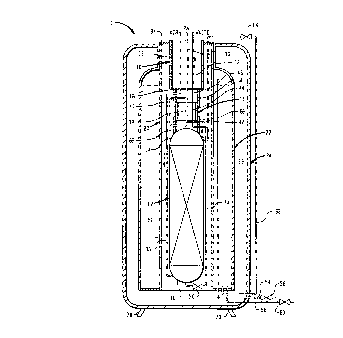
which the sole figure is a schematic illustration of an apparatus for
separating air in
accordance with the present invention.
DETAILED DESCRIPTION
With reference to the Figure, an apparatus 1 for separating air in accordance
with the present invention is illustrated. Apparatus 1 is a packaged air
separation plant
2

21g~0~a
of the type known as a liquid nitrogen assist plant. It is to be noted, that
the present
invention is not limited to any particular type of distillation apparatus and
has broader
applicability to distillation units which could be used to separate mixtures
other than air
and could employ multiple columns.
Apparatus 1 includes a main heat exchanger 10 for cooling air to a temperature
suitable for its rectification and a distillation column 12 that produces a
nitrogen
product within a tower overhead region 14 thereof and an oxygen enriched
liquid within
a liquid column bottoms region 16. Reflux to column 12 is produced within a
head
condenser 18 interposed between main heat exchanger 10 and distillation column
12.
Main heat exchanger 10, distillation column 12 and head condenser 18 are
mounted in
an in-line relationship within a sleeve 20. Sleeve 20 penetrates a liquid
nitrogen storage
container 22 which is in turn housed within a vacuum insulation tank 24
containing
insulation 26. Although not illustrated, sleeve 20 could be filled with
insulation to
prevent condensation of air. Insulation could also be utilized within sleeve
20 if
employed outside of vacuum insulation tank 24.
Main heat exchanger 10 and head condenser 18 are each of plate and fin
construction. Main heat exchanger 10 is provided with an air passage 28 and
countercurrent product nitrogen and waste passages 30 and 32 for the passage
of
product nitrogen and waste. Air cools within passageway 28 to a temperature
suitable
for its rectification, namely a temperature at or near the dewpoint of air. At
the same
time, product nitrogen and waste countercurrently flowing in product nitrogen
and waste
passages 30 and 32 warm to near ambient temperatures. Main heat exchanger 10
is
connected to a top suspension flange 34 which is in turn connected to vacuum
insulation tank 24. Top suspension flange 34 is removable to allow removal of
main
heat exchanger 10, heat condenser 18, and distillation column 12 from vacuum
insulation tank 24 as a unit. An air conduit 36 is connected to air passageway
28 for
introducing the air into column bottoms region 16 at distillation column 12.
3

2199Q~~
Head condenser 18 has a nitrogen passageway 38 connected to tower overhead
region 14 of distillation column 12 by a product conduit 40 which is also
connected to
product nitrogen passageway 30 of main heat exchanger 10. In such manner, part
of
the product nitrogen is condensed within nitrogen passageway 38 and is
introduced via
S a reflux conduit 42 back into tower overhead region 14 of distillation
column 12. The
coolant for such condensation is provided by a coolant passageway 44 within
head
condenser 18. Coolant passageway 44 is connected to waste passageway 32 via a
waste conduit 46. Coolant passageway 44 is linked to column bottoms region 16
of
distillation column 10 by means of a waste line 48. A suitable temperature
difference
between the oxygen-rich liquid contained within column bottoms region 16 and
the
product nitrogen to be condensed is provided by valve expanding a waste stream
(composed of the oxygen-rich liquid) by an expansion valve 50 provided within
waste
line 48.
In any cryogenic distillation column system, there invariably will be a heat
leakage from the environment. In order to counteract such heat leakage,
refrigeration
must be supplied. In air separation apparatus 1, such refrigeration is
supplied via liquid
nitrogen contained within liquid nitrogen storage tank 22. Liquid nitrogen
storage tank
22 contains liquid nitrogen 52 which is introduced into liquid nitrogen
storage tank 22
by fill line 54. A cutoff valve 56 is provided to close off fill line 54.
Additionally, a
drain line 58 is provided for draining liquid nitrogen 52 from liquid nitrogen
storage
tank 22 should the need arise. A cutoff valve 60 is provided within drain line
58. A
transfer line 62 causes liquid nitrogen to be introduced into tower overhead
region 14
of distillation column 12 in order to add refrigeration to distillation column
12. Valve
expansion, provided by an expansion valve 64, lowers the temperature of liquid
nitrogen
passing through transfer line 62.
Head condenser 18 is connected to main heat exchanger 10 by means of four
supports 66. Distillation column 12 is in turn suspended from head condenser
18 by
four supports 68. Supports 66 and 68 each have a rectangular transverse cross-
section.
It is to be noted that only two of each of supports 66 and 68 can be seen in
the Figure
4

2199A85
because the other unseen supports lie directly behind the illustrated two of
each of set
of supports 66 and 68. Preferably supports 66 and 68 are fabricated to flex
under
influence of gravitational force on distillation column 36. Such fabrication
can be
effected by appropriate choice of a flexible material and/or appropriate
sectional design
of the moment of inertia of each of supports 66 and 68. Thus, since vacuum
insulation
tank 24 rests on legs 70 and may not be perfectly level, distillation column
12
pendulously swings into a level position upon deformation of supports 66 and
68.
Nitrogen product line 40, air line 36, coolant line 46 are also made to flex
without
kinking by provision of bends or bellows-like joints and other well known
methods of
allowing piping system to have some "give".
As can be appreciated by those skilled in the art, main heat exchanger 10 and
head condenser 18 could be constructed as a single unit and as such,
distillation column
12 would be suspended from the main heat exchanger incorporating a head
condenser
into its design. Moreover, although main heat exchanger 10 is rigidly
connected to top
suspension flange 34, it could be flexibly supported from top suspension
flange 34 so
that the distillation column 12, main heat exchanger 10 and head condenser 18
swung
from such support.
Although sleeve 20 is illustrated as being mounted within a liquid nitrogen
storage tank 22 and in turn, vacuum insulation tank 24, this is only for
convenience of
packaging. Specifically, sleeve 20 could be made free standing on its own legs
and
connected by suitable piping to liquid nitrogen storage tank 22 mounted within
a
vacuum insulation tank.
While the present invention has been described with reference to a preferred
embodiment, as will occur to those skilled in the art, numerous changes,
additions and
omissions may be made without departing from the spirit and scope of the
present
invention.
5

Dessin représentatif
Une figure unique qui représente un dessin illustrant l'invention.
États administratifs

2024-08-01 : Dans le cadre de la transition vers les Brevets de nouvelle génération (BNG), la base de données sur les brevets canadiens (BDBC) contient désormais un Historique d'événement plus détaillé, qui reproduit le Journal des événements de notre nouvelle solution interne.

Veuillez noter que les événements débutant par « Inactive : » se réfèrent à des événements qui ne sont plus utilisés dans notre nouvelle solution interne.

Pour une meilleure compréhension de l'état de la demande ou brevet qui figure sur cette page, la rubrique Mise en garde , et les descriptions de Brevet , Historique d'événement , Taxes périodiques et Historique des paiements devraient être consultées.

Historique d'événement

Description Date
Le délai pour l'annulation est expiré 2004-03-04
Lettre envoyée 2003-03-04
Accordé par délivrance 2000-07-18
Inactive : Page couverture publiée 2000-07-17
Inactive : Taxe finale reçue 2000-04-13
Préoctroi 2000-04-13
Un avis d'acceptation est envoyé 1999-10-27
Lettre envoyée 1999-10-27
Un avis d'acceptation est envoyé 1999-10-27
Inactive : Approuvée aux fins d'acceptation (AFA) 1999-10-08
Modification reçue - modification volontaire 1999-09-23
Inactive : Dem. de l'examinateur par.30(2) Règles 1999-03-25
Demande publiée (accessible au public) 1997-10-30
Inactive : CIB attribuée 1997-07-22
Inactive : CIB en 1re position 1997-07-22
Inactive : CIB attribuée 1997-07-22
Inactive : Demandeur supprimé 1997-06-25
Inactive : Demandeur supprimé 1997-06-18
Modification reçue - modification volontaire 1997-04-23
Exigences pour une requête d'examen - jugée conforme 1997-03-04
Toutes les exigences pour l'examen - jugée conforme 1997-03-04

Historique d'abandonnement

Il n'y a pas d'historique d'abandonnement

Taxes périodiques

Le dernier paiement a été reçu le 2000-02-18

Avis : Si le paiement en totalité n'a pas été reçu au plus tard à la date indiquée, une taxe supplémentaire peut être imposée, soit une des taxes suivantes :

  • taxe de rétablissement ;
  • taxe pour paiement en souffrance ; ou
  • taxe additionnelle pour le renversement d'une péremption réputée.

Veuillez vous référer à la page web des taxes sur les brevets de l'OPIC pour voir tous les montants actuels des taxes.

Historique des taxes

Type de taxes Anniversaire Échéance Date payée
Taxe pour le dépôt - générale 1997-03-04
Requête d'examen - générale 1997-03-04
Enregistrement d'un document 1997-03-04
TM (demande, 2e anniv.) - générale 02 1999-03-04 1999-02-17
TM (demande, 3e anniv.) - générale 03 2000-03-06 2000-02-18
Taxe finale - générale 2000-04-13
TM (brevet, 4e anniv.) - générale 2001-03-05 2001-02-20
TM (brevet, 5e anniv.) - générale 2002-03-04 2002-02-21
Titulaires au dossier

Les titulaires actuels et antérieures au dossier sont affichés en ordre alphabétique.

Titulaires actuels au dossier
THE BOC GROUP, INC.
Titulaires antérieures au dossier
KARL O. TOPPEL
Les propriétaires antérieurs qui ne figurent pas dans la liste des « Propriétaires au dossier » apparaîtront dans d'autres documents au dossier.
Documents

Pour visionner les fichiers sélectionnés, entrer le code reCAPTCHA :


Pour visualiser une image, cliquer sur un lien dans la colonne description du document. Pour télécharger l'image (les images), cliquer l'une ou plusieurs cases à cocher dans la première colonne et ensuite cliquer sur le bouton "Télécharger sélection en format PDF (archive Zip)" ou le bouton "Télécharger sélection (en un fichier PDF fusionné)".

Liste des documents de brevet publiés et non publiés sur la BDBC .

Si vous avez des difficultés à accéder au contenu, veuillez communiquer avec le Centre de services à la clientèle au 1-866-997-1936, ou envoyer un courriel au Centre de service à la clientèle de l'OPIC.


Description du
Document 
Date
(aaaa-mm-jj) 
Nombre de pages   Taille de l'image (Ko) 
Page couverture 2000-06-23 1 41
Dessin représentatif 1997-12-03 1 18
Dessin représentatif 2000-06-23 1 14
Abrégé 1997-03-04 1 10
Description 1997-03-04 5 233
Revendications 1997-03-04 2 51
Dessins 1997-03-04 1 38
Dessins 1997-04-23 1 36
Page couverture 1997-12-03 1 45
Revendications 1999-09-23 2 57
Description 1999-09-23 5 236
Rappel de taxe de maintien due 1998-11-05 1 110
Avis du commissaire - Demande jugée acceptable 1999-10-27 1 164
Avis concernant la taxe de maintien 2003-04-01 1 174
Correspondance 2000-04-13 1 29