Note : Les descriptions sont présentées dans la langue officielle dans laquelle elles ont été soumises.
TYD-D408
~ 1 - 021 9~ 235
METHOD FOR MOUNTING TWO AUXILIARY MA~HIN~S TO AUTOMOBILE
AN~ POWER TRANSMISSION DEVICE
BACKGROUND OF THE INVENTION
1. Field of the Invention
The present invention relates to a method for
mounting two auxiliary machines to an automobile and a
power transmitting device therefor.
2. Description of the Related Art
An automobile has a power unit such as an
-internal combustion engine mounted in the automobile. An
automobile also includes auxiliary machines acting
auxiliarily to the power unit, such as a water pump, an
idler, a hydraulic pump for a power steering system, an
alternator, a compressor for an automobile air
conditioning system and so on. These auxiliary machines
have drive shafts to which power transmission members
such as pulleys or electromagnetic clutches are attached.
The power transmission members are connected to pulleys
on the crankshaft of the engine via a belt and driven by
the engine.
In mounting the auxiliary machines to the
automobile, it is necessary to arrange the auxiliary
machines in the restricted space around the engine. In
addition, it is desired to reduce the cost for mounting
the auxiliary machines to the automobile, by reducing the
respective power transmission members to save the number
of the parts.
Japanese Unexamined Patent Publication (Kokai)
No. 5-8633 discloses an automobile air conditioning
device which includes two auxiliary machines, i.e., a
viscous fluid type heat generator (herein, referred to a
viscous heater) and a compressor. The viscous heater and
the compressor are arranged to satisfy the above
described requirements. That is, the housing of the
viscous heater and the housing of the compressor are
- 2 02199 235
integrally formed as a unit, and a part of the drive
shaft of the viscous heater and the drive shaft of the
compressor are also formed as a unit. An electromagnetic
clutch acting as a power transmission member is arranged
on the remaining part of the drive shaft of the viscous
heater. In addition, these auxiliary machines are
mounted to the automobile, by fixing the housing of the
viscous heater and compressor to the engine or to the
automobile, using a single bracket.
However, in the above described mounting
method, it is necessary to modify the housing of the
viscous heater and the housing of the compressor, and the
manufacturing process of two auxiliary machines becomes
complicated and the manufacturing cost increases.
SUMMARY OF THE INVENTION
The object of the present invention is to overcome
the above described problems and to provide a method for
mounting two auxiliary machines to an automobile and a
power transmitting device adapted for use in this method.
The other object of the present invention is to
provide a method for mounting two auxiliary machines to
au automobile and a power transmitting device used in
this method, in which two auxiliary machines can be
arranged in a restricted space and one or some of the
power transmission members can be omitted without
rendering the manufacturing process complicated, so that
the manufacturing cost and thus the mounting cost can be
decreased.
According to the present invention, there is
provided a method for mounting first and second auxiliary
machines to an automobile having a power unit, said
method comprising the step of: coupling a drive shaft of
the first auxiliary machine and a drive shaft of the
second auxiliary machine in tandem by a power
transmitting device driven by the power unit of the
automobile and transmitting power of the power unit to
both said first and second auxiliary machines. By this
~ - 3 - 0 2 1 9 9 2 3 5
method, two auxiliary machines can be arranged in a
restricted space and one or some of the power
transmission members can be omitted without rendering the
manufacture process complicated so that the manufacture
cost and thus the mounting cost can be decreased.
The auxiliary machines can be a water pump, an
idler, a hydraulic pump for a power steering system, an
alternator, a viscous heater, a compressor for an
automobile air conditioning system and so on. The
viscous heater may be preferably used at a cold location.
Preferably, the method further comprises the step of
fixing a housing of the first auxiliary machine and a
housing of the second auxiliary machine to the power unit
or to the automobile via a common bracket. By this
feature, it is possible to reduce the number of the parts
and thus the manufacturing cost.
According to the present invention, there is
provided a power transmitting device in an automobile
having a power unit and first and second auxiliary
machines, each of the first and second auxiliary machines
having a housing and a drive shaft. The power
transmitting device comprises a rotor driven by the power
unit of the automobile, a first hub portion adapted to be
operably connected to the rotor and fixed to the drive
shaft of the f-irst auxiliary machine, and a second hub
portion adapted to be operably connected to the rotor and
fixed to the drive shaft of the second auxiliary machine.
Thus, the power transmitting device is adapted to couple
the drive shaft of the first auxiliary machine and the
drive shaft of the second auxiliary machine in tandem to
transmit power of the power unit to both said first and
second auxiliary machines.
Preferably, the power transmitting device further
comprises a common bracket to which the housings of the
first and second auxiliary machines are attached.
Preferably, the first hub portion and said second
hub portions are arranged in an opposing relationship on
~ 4 - 0 2 1 9 9 2 3 5
a common axis.
The rotor is rotatably supported by at least one of
the housings of said first and second auxiliary machines
and driven by the power unit of the automobile via a
belt.
The first and second hub portions may be fixed to
each other to rotate simultaneously.
The at least one of the first and second hub
portions may be coupled to the rotor via an
electromagnetic clutch.
The at least one of the first and second hub
portions may be coupled to the rotor via an
electromagnetic clutch.
One of the first and second hub portions may be
coupled to the rotor via an electromagnetic clutch, and
the other of the first and second hub portions is
directly coupled to the rotor.
One of the first and second hub portions may be
coupled to the rotor via a first electromagnetic clutch,
and the other of the first and second hub portions is
coupled to the rotor via a second electromagnetic clutch.
One of the first and second hub portions may be
coupled to the rotor via an electromagnetic clutch, the
electromagnetic clutch having a solenoid coil arranged on
one of the housings of the first and second auxiliary
machines, and an armature carried by one of the drive
shaft of the first and second auxiliary machines, the
armature being attracted to the rotor when voltage is
applied across the solenoid coil.
BRIEF DESCRIPTION OF T~E DRAWINGS
The other objects and features of the present
invention will become more apparent from the following
description of the preferred embodiments, with reference
to the accompanying drawings, in which:
Fig. l is a partially cross-sectional, side view of
the power transmitting device with two auxiliary machines
mounted to an automobile according to the first
~ ~ 2 1 9 9 2 3 5
-- 5
embodiment of the present invention;
Fig. 2 is a partially cross-sectional, side view of
the power transmitting device with two auxiliary machines
mount~d to an automobile according to the second
embodiment of the present invention;
Fig. 3 is a partially cross-sectional, side view of
the power transmitting device with two auxiliary machines
mounted to an automobile according to the third
embodiment of the present invention; and
Fig. 4 is a partially cross-sectional, side view of
the power transmitting device with two auxiliary machines
mounted to an automobile according to the fourth
embodiment of the present invention.
DESCRIPTION OF THE PREFERRED EMBODIMENTS
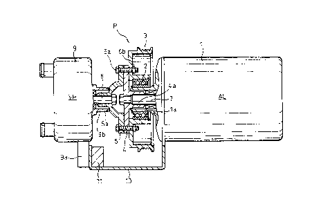
Referring to the drawings, Fig. 1 shows the first
embodiment of the present invention, in which an
alternator AL and a viscous fluid type heat generator
(hereinafter, referred to a viscous heater) VH are shown
as examples of auxiliary machines which work auxiliarily
relative to a power unit, such as an internal combustion
engine, of an automobile. The automobile is not shown in
the drawing, but it is representatively shown by a
housing 11 of the engine. The alternator AL and the
viscous heater VH are mounted to the automobile and
driven by the-engine via a power transmitting device
disclosed herein. The alternator AL has a housing 1 with
a boss portion la and a drive shaft 7. The viscous
heater VH also has a housing 9 with a boss portion 9b and
a drive shaft 8.
The power transmitting device has a rotor 3 arranged
about the boss portion la of the housing 1 of the
alternator AL and rotatably supported by a bearing 2 on
the boss portion la. A pulley P is formed on the outer
peripheral surface of the rotor 3 and includes V-shaped
3~ grooves to receive a belt by which the pulley P is
connected to a pulley (not shown) of the crankshaft of
the engine. Therefore, the rotor 3 can be driven by the
~ - 6 D2 199 235
engine.
A first hub member 4 and a second hub member 5 are
fixed to each other and to the rotor 3 by a plurality of
bolts 6a and nuts 6b. The first hub member 4 has an
axial projection 4a extending into the boss portion la of
the housing l and a central hole therethrough, so that
the first hub member 4 can be fixed to the drive shaft 7
of the alternator AL. The second hub member 5 has an
axial projection 5a extending into the boss portion 9b,
the axial projection 5a extending reverse to the axial
projection 4a of the first hub member 4, and a central
hole therethrough, so that the second hub member 5 can be
fixed to the drive shaft 8 of the viscous heater 9. In
this manner, the first and second hub portions 4 and 5
are arranged in an opposite relationship on a common axis
and the drive shafts 7 and 8 can be arranged and coupled
in tandem.
The viscous heater 9 also has an outwardly extending
flange 9a. The flange 9a of the housing 9 and the
housing 1 of the alternator AL are fixed to a common
bracket 10 which is fixed to the housing 11 of the
engine It is also possible to fix the housing 9 of the
viscous heater VH and the housing 1 of the alternator AL
to the automobile via the common bracket 10.
In this embodiment, the rotor 3 is driven ~y the
engine (power unit) via a belt, and the first and second
hub members 4 and 5 rotationally drive the drive shafts 7
and 8 of the alternator AL and the viscous heater VH.
The drive shaft 7 of the alternator AL and the drive
shaft 8 of the viscous heater VH are normally in the
operating condition while the engine operates.
Therefore, the viscous heater VH can quickly heat the
compartment in the automobile and the alternator AL can
normally charge the battery.
In the method for mounting two auxiliary machines
and an automobile, the drive shaft 7 of the alternator AL
and the drive shaft 8 of the viscous heater VH are
~ a2 1 ~9 235
-- 7
connected in tandem by the power transmitting device
including the pulley P, the rotor 3 and the first and
second hub members 4 and 5 to transmit power of the
engine to both the alternator AL and the viscous
heater VH. In this mounting method and in the power
transmitting device used for this method, it is not
necessary to modify the housing 1 and the drive shaft 7
of the alternator AL and the housing 9 and the drive
shaft 8 of the viscous heater VH.
Therefore, according to this method, it is possible
to satisfy the need to mount the alternator AL and the
viscous heater V~ in a restricted mounting space and the
requirement to omit one of the pulleys, which would
otherwise be necessary. It is therefore possible to
reduce the manufacturing cost of the alternator AL and
the viscous heater VH, without any difficulty in
manufacturing the alternator AL and the viscous
heater VH.
Also, in this method, it is possible to reduce the
mounting cost during the mounting operation of the
alternator AL and the viscous heater VH to the
automobile, thanks to the simple arrangement and the
reduction of the parts, since the housing 1 of the
alternator AL and the housing 9 of the viscous heater VH
are fixed to t-he engine via the common bracket 10.
Figure 2 shows the second embodiment of the present
invention, in which a compressor AC for an automobile air
conditioning system and a viscous heater VH are shown as
examples of auxiliary machines. The viscous heater VH is
similar to that of Fig. 1. The compressor AC has a
housing 12 and a drive shaft 16 and also driven by the
engine via a power transmitting device. In this case,
the power transmitting device includes an electromagnetic
clutch MC having a solenoid coil 15 and an armature 20.
The power transmitting device has a rotating
member 14 arranged about the boss portion 12a of the
housing 12 of the compressor AC and rotatably supported
- 8 - 0 2199 235
by a bearing 13 on the boss portion 12a. The solenoid
coil 15 of the electromagnetic clutch MC is attached to
the housing 12 of the compressor AC and located in the
ring-shaped recess in the rotating member 14 at the rear
side thereof. The armature 20 of the electromagnetic
clutch MC is arranged facing the front surface of the
rotating member 14 so that the armature 20 is attracted
toward the rotating member 14 by the magnetic force of
the solenoid coil 15 when voltage is applied across the
solenoid coil 15.
The drive shaft 16 of the compr,essor AC is fixed to
a first hub member 17 extending in the boss portion 12a,
the first hub member 17 being connected to the
armature 20 via a rubber member (elastic member) 18 and a
flange 19. A cup-shaped member 21 is fixed to the
rotating member 14 by bolts 22, and is rotatably
supported by a bearing 41 on a boss portion 9b of the
housing 9 of the viscous heater VH. The cup-shaped
member 21 has a pulley P and a second hub portion 23
which extends reverse to the first hub member 17 and is
fixed to the drive shaft 8 of the viscous heater VH. In
this manner, the first and second hub portions 17 and 23
are arranged in an opposite relationship on a common axis
and the drive shafts 16 and 8 are arranged and coupled in
tandem. In this case, the cup-shaped member 21 and the
rotating member 14 constitute a rotor. The other
arrangement is similar to the first embodiment.
In this embodiment, the cup-shaped member 21 and the
rotating member 14 are driven by the engine (power unit)
via a belt. The armature 20 is attracted to the rotating
member 14 by the magnetic force of the solenoid coil 15
and rotates with the cup-shaped member 21 and the
rotating member 14 while the solenoid coil 15 is
energized. Thus, the first hub member 17 rotationally
drives the drive shaft 16 of the compressor AC while the
armature 20 rotates. Also, the second hub member 23
rotationally drives the drive shaft 8 of the viscous
~2 1 ~9 235
~ g
heater VH while the cup-shaped member 21 and the rotating
member 14 rotate. The solenoid coil 15 can be
deenergized according to a signal to stop the drive
shaft 16 of the compressor AC while the engine is
rotating. The drive shaft 8 of the viscous heater VH is
always in the operating condition. Therefore, it is
possible to satisfy the requirements, in a cold location,
that the viscous heater VH can quickly heat the
compartment in the automobile and that the compressor AC
can sometimes operate.
In the method for mounting two auxiliary machines to
an automobile in this embodiment, it is possible to
obtain advantages similar to those of the previous
embodiment.
Figure 3 shows the third embodiment of the present
invention, in which an alternator AL and a viscous
heater VH are shown as examples of auxiliary machines.
The alternator AL and the viscous heater VH are similar
to those o~ Fig. 1. In this case too, the power
transmitting device includes an electromagnetic
clutch MC.
The power transmitting device has a rotor 25
arranged about the boss portion la of the housing 1 of
the alternator AL and rotatably supported by a bearing 24
on the boss portion la. The rotor 25 has a pulley P. A
solenoid coil 26 of the electromagnetic clutch MC is
attached to the housing 1 of the alternator AL and
located in the ring-shaped recess in the rotor 25 at the
rear side thereof.
The drive shaft 7 of the alternator AL is fixed to a
first hub member 27 extending in the boss portion la, and
the first hub member 27 is connected to the armature 30
via a rubber member (elastic member) 28 and a flange 29,
the armature 30 facing the front surface of the rotor 25.
A second hub portion 31 which extends reverse to the
first hub member 27 is fixed to the first hub member 27
by bolts 32. The second hub portion 31 is fixed to the
- lo 0 2 1 9 9 2 ~ 5
drive shaft 8 of the viscous heater VH. In this manner,
the first and second hub portions 27 and 31 are arranged
in an opposite relationship on a common axis and the
drive shafts 16 and 8 are arranged and coupled in tandem.
The other arrangement is similar to the first embodiment.
In this embodiment, the rotor 25 is driven by the
engine (power unit) via a belt. The armature 30 is
attracted to the rotor 25 by the magnetic force of the
solenoid coil 26 and rotates with the first rotating
member 25 while the solenoid coil 26 is energized. Thus,
the first hub member 27 rotationally drives the drive
shaft 7 of the alternator AL and the second hub member 31
rotationally drives the drive shaft 8 of the viscous
heater VH while the armature 30 rotates. The solenoid
lS coil lS can be deenergized according to a signal to
simultaneously stop the drive shaft 7 of the
alternator AL and the drive shaft 8 of the viscous
heater VX while the engine is rotating. The drive
shaft 8 of the viscous heater VH is always in the
operating condition. Therefore, it is possible to
realize the requirement in the initial stage of the
operation of the engine such that the viscous heater VH
can quickly heat the compartment in the automobile and
the alternator AL can charge the battery, and in the
later stage of- the operation of the engine, it is
possible to stop the heating by the viscous heater VH and
to prevent overcharging by the alternator AL.
In the method for mounting two auxiliary machines to
an automobile in this embodiment, it is possible to
obtain advantages similar to those of the previous
embodiment.
Figure 4 shows the fourth embodiment of the present
invention, in which a hydraulic pump PP for a power
steering system and a viscous heater VH are shown as
examples of auxiliary machines. The pump PP has a
housing 33 and a drive shaft 37 and the viscous heater VH
is similar to that of Fig. 1. In this case, the power
~ 11 -02~ 99 235
transmitting device includes electromagnetic clutches.
The power transmitting device has a first rotating
member 35 arranged about the boss portion 33a of the
housing 33 of the pump PP and rotatably supported by a
bearing 34 on the boss portion 33a. A first solenoid
coil 36 of the first electromagnetic clutch is attached
to the housing 33 of the pump PP and located in the ring-
shaped recess in the first rotating member 35 at the rear
side thereof. The drive shaft 37 of the pump PP is fixed
to a first hub member 38 extending in the boss
portion 33a, and the first hub member 38 is connected to
a first armature 40 of the first electromagnetic clutch
via a rubber memb,er (elastic member) 38 and a flange 39,
the first armature 40 facing the front surface of the
first rotating member 35.
The power transmitting device has a second rotating
member 42 arranged about the boss portion 9b of the
housing 9 of the viscous heater VH and rotatably
supported by a bearing 41 on the boss portion 9b. A
second solenoid coil 43 o~ the second electromagnetic
clutch is attached to the housing 9 of the viscous
heater vH and located in the ring-shaped recess in the
second rotating member 42 at the rear side thereof. The
drive shaft 8 of the viscous heater VH is fixed to a
second hub member 44 extending in the boss portion 9b of
the viscous heater VH, and the second hub member 44 is
connected to a second armature 46 of the second
electromagnetic clutch via a rubber member (elastic
member) 45 and a flange 46, the armature 46 facing the
front surface of the second rotating member 42.
A cylindrical member 47 is fixed to the first and
second rotating members 35 and 42 by bolts 48 and 49.
The cylindrical member 47 has a pulley P. The first and
second rotating members 35 and 42 and the cylindrical
member 47 constitute a rotor. In this manner, the first
and second hub portions 38 and 44 are arranged in an
opposing relationship on a common axis and the drive
- 12 _ 0 2 1 9 9 2 3 5
shafts 16 and 8 are arranged and coupled in tandem. The
other arrangement is similar to the first embodiment.
In this embodiment, the first and second rotating
members 35 and 42 and the cylindrical member 47 are
driven by the engine (power unit) via a belt. The first
armature 40 is attracted to the first rotating member 55
by the magnetic force of the first solenoid coil 36 and
rotates with the first and second rotating members 35 and
42 and the cylindrical member 47, and the second
armature 46 is attracted to the second rotating member 42
by the magnetic force of the second solenoid coil 43 and
rotates with the first and second rotating members 35 and
42 and the cylindrical member 47, while the first and
second solenoid coils 36 and 43 are energized. Thus, the
first hub member 38 rotationally drives the drive
shaft 37 of the pump PP while the first armature 40
rotates. The second hub member 44 rotationally drives
the drive shaft 8 of the viscous heater VH while the
second armature 46 rotates. The first and second
solenoid coils 36 and 43 can be deenergized according to
respective signals to separately stop the drive shaft 37
of the pump PP and the drive shaft 8 of the viscous
heater VH while the engine is rotating. Therefore, it is
possible to realize the requirement in the initial stage
of the operation of the engine such that the viscous
heater VH can quickly heat the compartment in the
automobile, and in the later stage of the operation of
the engine, it is possible to stop the pump PP.
In the method for mounting two auxiliary machines to
an automobile in this embodiment, it is possible to
obtain advantages similar to those of the previous
embodiment.