Note : Les descriptions sont présentées dans la langue officielle dans laquelle elles ont été soumises.
CA 02199313 2003-04-29
TITLE: ACCESS DO<)R FOR OFFICE PANELLING FRAME
FIELD OF THE INVE 1VTION
The present invention relates to office panelling systems and in
particular it relates to an office panel having an access door which is
moveable about a hinge to access electrical receptacles behind the access
door and where the access door in a closed position is positively held
against the frame to eliminate unwanted movement of the access door.
BACKGROUND OF THE INVENTION
An office parceling system is disclosed in our earlier United
States patent 4,535,577. This system has individual office panels which are
connected in an end to end manner or in an angled manner. Each office panel
has an interior frame to which decorative or functional cover elements are
secured to provide a firuished surface to either side of the frame. Various
horizontal channels are provided across the frame for securing of office
accessories such as work .surfaces, overhead bins and other accessory
structures. 'Chis panelitrg system provides ready access to power at desk
height. This is achieved by providing an access door at approximately desk
height which access door can be hinged about a top hinge axis exposing a
compartment within the office panel frame. The face of electrical receptacles
are provided in a horizc~wtal member of the frame electrical equipment and
can be plugged into the receptacle. in addition, excess electrical cord is
stored
in the panel 'behind the access door. Tn this structure, the hinge access door
is
held by gravity against the base of the frame.
There are other office panelling systems where the securement
of a hinged access door is similar to the securernent of other releasable
elements applied to the frame. For example, some releasable elements are
merely held 'by a spring cYip type arrangement to the face of an office panel
3 5 frame. These securement approaches can use a conventional plug and
receptacle type arrangement or as shown in our earlier patent can use a
-1-
WH-9775CA
2~993~3
hinge and spring clip type arrangement where the elements pivot about a
lower surface of the element and engage spring clips at an upper surface of
the element.
Originally office panel systems were designed to support a work
surface at a predetermined height and the lower edge of the access door
was positioned slightly above the level of the work surface. In this way,
the hinging of the access door outwardly would expose the electrical plugs
behind the access door. With increased computer technology variable
height work surfaces were more common and the predetermined
relationship of the work surface and the lower edge of the access door was
not necessarily present. Workers have personal preferences with respect
to work height which can be dependent on their physical size, and/or their
preferences and it has also been found that changes in the work station
during a day is also desirable. There are now many arrangements from
relatively simple height adjustment arrangements to hydraulic height
adjustment arrangements whereby the height of a work surface is easily
changed.
2 0 In many cases a work surface is at the predetermined height and
does have the required relationship allowing the access door to pivot
outwardly missing the work surface and thus the access door works in its
intended manner. However, in other circumstances the work surface is
positioned to block the access door. Fortunately once a work station is set
up access to the interior of the panel is less frequent.
The present invention provides a structure which allows
convenient access to the interior of the panel frames regardless of whether
the work surface is at height overlapping with the access door.
~LTMMARY OF THE INVENTION
An office panelling system according to the present invention
has a series of connected office panels and each office panel has a frame
3 5 defining a hollow interior through which electrical wiring conduits and
communication conduits extend. Each panel includes releasable elements
-2-
CA 02199313 2003-04-29
either side of the frame which define a finished surface of the office panel
frame. Some of the releasable elements are access doors for conveniently
accessing electrical receptacles located in the frame behind the respective
access door. Each access door is pivotable about a hinge axis to an open
position exposing the electrical receptacles and each access door in a closed
position includes a positive securing arrangement to eliminate unwanted
hinge movement of the access door. Each access door includes a securing
bracket arrangement comprising a first bracket attached to the access door
and a second bracket hin;~edly connected to the first bracket and releasably
attached to the respective office panel frame for allowing removal of the
access door from the respective office panel frame.
According to an aspect of the invention the releasable
securement of the securing arrangement to the frame is a spring clip
arrangement which engages in upper edge of the securing arrangement.
BRIEF DESCRIPTION CIF THE DRAWINGS
Preferred emlao~diments of the invention are shown in the
drawings wherein:
Figure 1 is a partial perspective view of an office paneling
system with a variable lueight work surface in front thereof;
Figure 2 is a side view showing a work surface in movement of
an access door to an open position;
Figure 3 is a side view of an office panel where the access door is
being removed;
Figure 4 is a partial perspective view showing securement of an
access door to an office panel frame;
-3-
CA 02199313 2003-04-29
Figure 5 is side view showing the securement of the access door
to the frarr~e of an office panel,: and
Figure 6 is side view showW g removal of an access door from an
office panel frame.
DETAILED DESCRIPTION ACCORDING TO THE PREFERRED
EMBODIMENTS OF THLE PRESENT INVENTION
An office panelling system 2 shown in Figure 1 comprises a
series of connected office panels 4. In front of the office panels is a
variable
height work surface 6. Each office panel 4 includes releasable elements 8
which are secured to the frame of the office panel. These releasable
elements d<~fine an exterior finish surface, decorative surface or functional
surface to either side of the office panel. In addition, there are series of
releasable access door elements 10. These access door elements can hinge
outwardly ~~s shown irt Figure 2 such that the electrical wire 12, with a
2 0 suitable plug on the end thereof, can be inserted in an electrical
receptacle
interior to tlae frame of the office panel (see Fig. 6). Excess wire can also
be
retained wii:hin the parcel frame. The hinging of the access door and the
accumulatie~n of wire and its relationship with the work surface as shown
in Figure 2 ;is shown in our earlier United States patent 4,535,577.
With variable height work surfaces, a problem arises in that the
access door element 10 carp overlap with a work surface as shown in Figure
3. In this case, the work surface 6 is above the lower edge of the access door
and the work surface blocks access to the interior of the panel. To
3 0 overcome this problem, the access door 10 is removable as indicated in
Figure 3. Basically the top of the access door is releasably held in a spring
detente relationship with the frame of the office panel and the access door
is pivotable about a lower edge. In this way, the top of the door element is
pulled outwardly releasing the spring detente and then the access door
may be removed as indicated by arrow 7 in Figure 3. This will be more
fully explained with respect to Figures 4, 5 and 6.
-4-
W 2199313
WH-9775CA
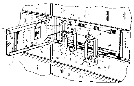
The access door element 10 shown in Figure 4 has a channel
support 22 to which a finished surface 20 is secured. The channel support
22 can include knock out areas such as 26 to allow communication
receptacles to be secured to the access door and exposed on the exterior of
the access door. Communication wiring is low voltage and it is often
desirable to provide convenient fast access-thereto and this is easily
accomplished by providing an outlet on the base of the access door.
T'he access door element 10 has a bracket arrangement 29 which
comprises an access door bracket 30 and a cooperating panel frame bracket
40. The access door bracket 30 has a spring clip 31 which releasable engages
the spring clip 41 provided on the panel frame bracket 40. These clips
form a releasable securement of access door bracket to the panel frame
bracket 40. The access door bracket 30 is hinged to the panel frame bracket
at hinge pin 52. The hinge pin 52 engages two rearwardly extending flange
members 35 and is received in the bearing port 45 provided on panel
frame bracket 40. With this arrangement the access door bracket 30 is free
to rotate about the hinge pin 52. The access door bracket 30 is positively
2 0 secured to the panel support 22 at the points indicated as 32 and 33 in
the
access door bracket and the securement points 21 and 23 on the channel
support 22.
A similar two piece bracket arrangement is provided adjacent
the opposite end of the access door element 10 and securement of the
access door to the office panel frame can be appreciated from Figures 5 and
6.
In Figure 5, the access door bracket 30 and the panel frame
3 0 bracket 40 are held together due to the hinge pin 52 in combination with
the engagement of spring clips 31 and 41.
The panel frame bracket 40 includes a downwardly extending
foot 56 which is received behind the securing channel 14 of the office
3 5 panel frame. With this arrangement the access door is moved
downwardly to bring the foot into the channel 14 and then rotated it
-5-
CA 02199313 2003-04-29
inwardly 1:o bring spring clip 42 into positive securement with spring clip
54 attached to the panel frame. 'I"he actual secured position is shogun in
Figure 5. tt can also l>e appreciated from. a review from Figure 5 that the
foot 56 rests on and i:., supported by the horizontal surface 44 of the
securing channel 14. The panel frame bracket 40 can also include
outwardly extending tabs 47 for engaging a vertical portion of the panel
frame to stop any in~n;-ard movement above the panel frame bracket 40.
Basically tike tab is on the outside of the frame and the foot is on the
inside
thus trapping the bracket in the desired position. Tabs 47 are provided
either side of the braclket 40 such that the bracket can be used at either end
of the access door element. These tabs can also be relocated for engage the
top edge of a support channel and thereby oppose inward movement of
the panel frame bracket.
With the arrangement as shown, particularly in Figure 5, the
access door bracket anal the panel frame bracket cooperate with the office
panel frame to allow i:he desired hinge movement of the access door
element 10 about the hinge pin 52. In addition, when the access door is
moved to the closed position (i.e. the relative position of the access door
bracket and the panel frame bracket shown in Figure 6) the brackets are
positively connected due to the engagement of spring clips 31 and 41. The
panel frame bracket 4(~ is secured in a releasable manner by the spring clip
54 on the panel frame engaging spring clip 42 on the bracket 40.
V'Jhen desired for example as would be the case if a user wanted
access to are electrical falug located behind the access door 10 with a work
surface as shown in Fi;~nire 3, the access door may be removed from the
panel frame as shown in Figure 6. The access door is initially rotated in
the direction of arrow T 1 to release spring clip 42 from spring clip 54. Once
3 0 this release has been achieved the access door as well as the access door
bracket and the panel frame bracket are removed as a unit in the direction
indicated by arrow 9 . Once the access door has been removed the user
then has full access to any part of the port exposed above the work surface.
An electrical plug 100 can be removed or inserted in the receptacle
3 5 indicated as 102.
_6_
CA 02199313 2003-04-29
In Figure 4, the access door bracket 30 and the panel frame bracket
40 are shown in exploded positions and aligned with one another. It is
possible to provide guide surfaces adjacent the cutout areas which engage the
opposite bracket to thE:~reby remove any sideways play when the door is in the
closed condition.
T'he interior surface of the access door element preferably
includes knock out portions 26. These can be provided in the channel 22
at the time of manufacture and only used if desired. It can be appreciated
that the decorative surface 20 can be appropriately removed in the area of a
knock out when an outlet is to be installed.
A. gasket member 66 has been provided adjacent the lower edge
of the access door to close the gap between the bottom edge of the access
and the panel frame. This gasket member is readily deformable to
accommodate wires which extend under the door.
Although prefexred embodiments of the invention have been
described here in detail, it will be understood by those skilled in the art
that
variations rrtay be made thereto without depriving the sprit of the
invention or the scope c~f the appended claims.