Note : Les descriptions sont présentées dans la langue officielle dans laquelle elles ont été soumises.
CA 02200030 2005-08-22
26456-96
- 1 -
BACKGROUND OF THE INVENTION
Field of the Invention
The present invention relates to a syringe with a
liquid leak preventing mechanism, and specifically to a
mechanism for preventing liquid leaking from syringe.
Description of Related Art
In a two-ingredient type pre-filled syringe
charged with a predetermined medicine and a liquid such as
its dissolution liquid, its dispersing liquid or other
medicinal liquids in the separated states, of the disposable
type syringes previously filled with a medicine, so-called
pre-filled syringes, conventionally as exemplified in
Fig. 10, a syringe having such a construction that an end
sealing member 32 is inserted through a rear end opening
into a cylindrical receptacle or barrel 31 provided at its
leading end portion with a mounting portion for a needle.
The barrel 31 has an intermediate sealing member 33 arranged
therein so as to be slidable in a longitudinal or axial
direction and to have a first chamber 34 on the leading end
side and a second chamber 35 on the rear end side divided
therein to receive a medicine P and a dissolution liquid L
within the respective chambers with its leading end portion
closed by a cap 37.
This type one has such a construction that the
first chamber 34 on the leading end side ahead of the
intermediate slidable sealing member 33 has a bypass
portion, usually an outward protruded bypass channel 36
arranged in the side wall of the barrel 31. At the time of
use, the intermediate sealing member 33 is advanced together
with the liquid L within the second chamber 35 by pushing
the end sealing member 32 by means of a rod as shown in
CA 02200030 2005-08-22
26456-96
- 2 -
Fig. 11 and the liquid L within the second chamber 35 is
made to flow into the first chamber 34 through the bypass
channel 36 when the intermediate sealing member 33 reaches
the channel 36. As shown in Fig. 12, subsequently thereto,
the intermediate sealing member 33 is pushed by the leading
end of the end sealing member 32 to perform the dissolution,
the dispersion or the mixing within the first chamber 34 and
then the liquid is pushed out of the leading end.
Thereupon, since the end sealing member passes
over the bypass portion, the liquid remaining in the bypass
portion leaks behind the end sealing member. Therefore, a
mechanism for preventing a liquid leak outside the syringe
by arranging a partition plate behind the end sealing member
is proposed in U.S. Patent No. 4,613,326.
In such a method, however, a low-viscosity
medicinal liquid, a small surface-tension liquid and the
likes happen to pass through a gap between the partition
plate provided in the plunger rod and the barrel inner wall,
and it is apprehended that the medicinal liquid remaining in
the partition plate is flowed out when the plunger rod is
removed from the syringe for fractional scrapping.
Therefore, it is an object of an embodiment of the
invention to provide a syringe with a liquid leak preventing
mechanism which is capable of preventing a medicinal liquid
from passing out through a gap between a receptacle or
barrel inner wall and a partition plate and also from
flowing out when a plunger rod is dismounted from the
syringe for fractional scrapping.
SUMMARY OF THE INVENTION
According to a first aspect of the present
invention, there is provided a syringe comprising:
CA 02200030 2005-08-22
26456-96
- 3 -
a tubular barrel having distal and proximal end
portions opposite to each other and also having an interior
hollow defined therebetween, said distal end portion being
sealed and engageable with a needle for injection of medical
substances to be mixed in said hollow and said proximal end
portion being sealed by a slidable end sealing member
connectable with a rod for making said end sealing member
slidable in an axial direction in said barrel;
at least one intermediate sealing member inserted
into said barrel, said intermediate sealing member dividing
the interior of said barrel in a sealed manner into a first
chamber for receiving a first medical substance and a second
chamber for receiving a second medical substance, said
intermediate sealing member being slidable in said barrel in
response to sliding of said end sealing member in said
barrel;
at least one bypass portion formed axially along
said barrel between said intermediate sealing member and
said distal end portion, said bypass portion permitting said
second medical substance to bypass said intermediate sealing
member and be introduced into said first medical substance
to be mixed therewith;
wherein said intermediate sealing member has an
axial length or thickness shorter than that of said bypass
portion;
at least one liquid-absorbent element capable of
absorbing the liquid and holding it therein, said liquid-
absorbent element positioned behind one of end faces of said
end sealing member opposite to said second chamber in said
barrel.
CA 02200030 2005-08-22
26456-96
- 3a -
In the present invention, the meaning of
"positioned behind one of end faces of said end sealing
member opposite to said second chamber in said barrel"
includes any cases that the liquid-absorbent element is
positioned behind said end sealing member with respect to a
longitudinal direction of the barrel. For
CA 02200030 2005-08-22
-4-
example, in one case, said liquid-absorbent element may be positioned at no or
some intervals from said end face of said end sealing member with respect to
the
longitudinal direction of the barrel. In the other case, said liquid-absorbent
element may be positioned as an end stopper for closing an end opening of said
S barrel.
Therefore, in a case of a two-chamber syringe including at least one
intermediate slidable sealing member inserted into a cylindrical barrel having
a
leading end portion to which a needle is mounted and a rear end opening into
which a plunger rod is inserted, said barrel is divided into a forward first
chamber
and a backward second chamber by the intermediate sealing member, said first
chamber receiving a certain medicine and said second chamber receiving a
liquid
to be mixed with the medicine. The rear end side of the backward second
chamber
which has received the liquid can be closed by inserting therein an end
slidable
sealing member adapted to be pushed by a leading end of said plunger rod. Said
intermediate slidable sealing member is displaced forwards to a region of the
bypass portion by means of said plunger rod, so that the liquid within the
second
chamber can be made to flow into the first chamber through the bypass portion
and is mixed with the medicine within the first chamber. Said liquid-absorbent
mechanism or element is arranged behind said end slidable sealing member with
no or some intervals and is capable of absorbing and holding the liquid
flowing
out behind the end sealing member.
According to the present invention, when the end slidable sealing
member passes absolutely over the bypass portion, the liquid flowing out
behind
the end slidable sealing member is absorbed and held by the liquid-absorbent
mechanism, so that it is possible to prevent the liquid leakage and dispersion
out
CA 02200030 2005-08-22
- 5 -
of the syringe barrel even when the plunger rod after use is removed at the
time
of fractional scrapping.
Generally, the syringe barrel is transparent so that the residual liquid
can be seen from outside, and it is apprehended that the leak occurs because
the
syringe barrel is merely shielded. According to the present invention, the
liquid
itself is securely held in the absorbed and held condition, so that it becomes
possible to dissolve such a problem.
Especially, in a case that the liquid-absorbent material is impregnated
with a water-holding and liquid-absorbing agent, it is possible to perfectly
attain
, a liquid-absorbent and holding effect even though a clearance exists between
the
liquid-absorbent element and the inner surface of the syringe.
Further, since microorganism tends to increase in the liquid-
absorbent material owing to its material property, the material can contain an
antimicrobial active agent together with the water-holding and liquid-
absorbing
agent or separately. Therefore, it is possible to prevent the increasing of
the
microorganism which tends to grow in the liquid-absorbent material and thereby
to enhance a safety at the time of fractional scrapping.
BRIEF DESCRIPTION OF THE DRAWINGS
The above and other objects and features of the present invention
will become more apparent from the following description of a preferred
embodiment thereof with reference to the accompanying drawings, throughout
which like parts are designated by like reference numerals, and wherein:
Fig. 1 is a sectional view showing a basic construction of an
embodiment of the present invention;
CA 02200030 2005-08-22
-6-
Figs. 2A and 2B are explanatory views of an assembling procedure
of a syringe main body including the charging of medicine and the likes;
Fig. 3 is a sectional view showing a construction of a concrete
embodiment of the present invention in the case that a movable type sealing
S member is employed at the leading end opening portion of a cylindrical
barrel;
Fig. 4 is an explanatory view of a function during the use of the
embodiment of Fig. 3;
Fig. 5 is a sectional view showing another embodiment of the
present invention in the case that an immovable type sealing member is
employed
at the leading end opening portion of the cylindrical barrel and a double-
pointed
needle is used as a needle;
Figs. 6A to 6C are explanatory views showing steps from the start
to the end of injection mechanism according to the present invention;
Figs. 7A to 7F are explanatory view showing steps from the start to
the end of injection mechanism according to the present invention;
Fig. 8 is a sectional view showing an embodiment to which a
countermeasure for decreasing an injecting loss quantity of the injection is
applied
in a two-ingredient pre-filled syringe of the present invention;
Fig. 9 is a perspective view of outlooks of respective sealing
members 3a, 3b, 3c;
Fig. 10 is a sectional view showing a construction of a conventional
two-ingredient pre-filled syringe;
Fig. 11 is an explanatory view of a first working thereof;
Fig. 12 is an explanatory view of a second working thereof;
CA 02200030 2005-08-22
_ 7 _
Fig. 13 is a schematic view showing an arrangement of a first
embodiment of a liquid leak preventing mechanism for use in the present
invention;
Fig. 14 is a side view showing a first attaching mechanism of the
first embodiment;
Fig. 15 is a front view showing the first attaching mechanism of the
first embodiment;
Fig. 16 is a side view showing a second attaching mechanism of the
first embodiment;
Fig. 17 is a front view showing the second attaching mechanism of
the first embodiment;
Fig. 18 is a side view showing an attaching mechanism of the second
embodiment;
Fig. 19 is a schematic view showing an arrangement of a second
embodiment of the liquid leak preventing mechanism for use in the present
invention;
Fig. 20 is a schematic view showing an arrangement of a third
embodiment of the liquid leak preventing mechanism for use in the present
invention;
Fig. 21 is a schematic view showing a variant example of the third
embodiment of the liquid leak preventing mechanism for use in the present
invention;
Fig. 22 is a perspective view showing a fourth embodiment of the
liquid leak preventing mechanism for use in the present invention.
CA 02200030 2005-08-22
- g _
Fig. 23 is a sectional side view showing a first mode pushing-in
condition of the fourth embodiment of the liquid leak preventing mechanism for
use in the present invention; and
Fig. 24 is a sectional side view showing a second mode pushing-in
condition of the fourth embodiment of the liquid leak preventing mechanism for
use in the present invention.
Fig. 25 is a sectional side view showing a first liquid-absorbent end
stopper for use in the present invention; and
Fig. 26 is a sectional side view showing a second liquid-absorbent end
stopper for use in the present invention.
DETAILED DESCRIPTION OF THE PREFERRED EMBODIMENTS
The liquid absorbing mechanism or element M may be mounted in
the barrel by three ways as follows.
1) The liquid absorbing element may be mounted integrally or
detachably on the backside of the end slidable sealing member which is mounted
integrally or detachably on one end portion of the plunger rod inserted within
the
barrel. Accordingly, as shown in Fig. 13, it may be constructed by attaching
to
the leading end of the plunger rod 2 a slidable disk-shaped liquid-absorbent
material D selected from the group consisting of a filter paper, a nylon felt,
a
cotton non-woven fabric, fibers as yarn or fabric, or resin such as water
absorbing
polymer. As shown in Figs. 14 and 15, threads are formed at a leading
protruded
portion 2a of the rod 2 while a threaded hole H is formed in the disk-shaped
liquid-absorbent material D at its center so as to be threadably engaged and
fitted
into a groove 2b. Further, as shown in Figs. 16 and 17, a twist lock is formed
at
a leading end portion 2a' of the rod 2 while a twist hole H' is formed in the
CA 02200030 2005-08-22
-9-
disk-shaped liquid-absorbent material D at its center so as to be engaged by
the
twisting and fitted into the groove 2b. Furthermore, the plurality of disk-
shaped
liquid-absorbent material D may be prepared and arranged in a stacked manner
or in a spaced apart manner.
2) On the other hand, the liquid-absorbent element M may be
positioned at one end of the barrel as an end stopper for closing an end
opening
in a separate manner from the end slidable sealing member. Accordingly, as
shown in Fig. 25, a disk-shaped end stopper S similar to the liquid-absorbent
material D has a through hole (h) for receiving the rod 2 at the center
thereof and
is arranged in a non-slidable manner just behind the backside of the end
sealing
member 3c. Further, as shown in Fig. 26, the disk-shaped end stopper S has
also
a through hole (h) for receiving the rod 2 at the center and may be fitted in
a
receiving space within a fitting cap portion 100a of a finger grip 100 which
is
mounted on the end lb of the barrel 1.
3) Further, the liquid-absorbent element M may be the disk-shaped
material D mounted on the backside of the end sealing member in a slidable
manner and additionally includes the end stopper S mounted at the end of the
barrel in a non-slidable manner.
The liquid-absorbent element M can be provided by winding the
filter paper or the fibers in the form of yarn, fabric, or non-woven fabric
around
a winding groove 2c formed at the leading end of the plunger rod 2 as shown in
Fig. 18 (refer to Fig. 19). Though Fig. 19 shows the one which is mounted only
to the leading end by the winding, it may be wound along the longitudinal
direction of the plunger rod. By the way, since an external configuration of
the
liquid-absorbent material defines a clearance relative to an inner wall of the
CA 02200030 2005-08-22
- 10-
syringe, in consideration of a surface tension and viscosity of the liquid,
the
clearance may be made small so as to become 0.2 - 1.0 mm in the case of the
liquid having a small surface tension like an alcohol and may be made large so
as
to become 0.2 - 1.5 mm in the case of the one having a comparatively large
surface tension like a water.
Though the above-mentioned liquid-absorbent element M is
embodied by such a material as to have the liquid absorbing capability, it may
be
constructed by utilizing the capillary phenomenon provided by annular or
spiral
liquid absorbing grooves C formed at the leading end of the plunger rod 2 as
shown in Fig. 20. Further, as shown in Fig. 21, the grooves may be provided by
arranging a plurality of disks 2e side by side in a stacked state in addition
to and
behind the disk 2d at the leading end of the plunger rod 2 as shown in Fig.
21.
Also in this case, it is preferable to define a groove width and its depth in
consideration of the viscosity and the surface tension of the liquid.
Further, as shown in Fig. 22, the above-mentioned liquid-absorbent
element M may have the cylindrical barrel formed of a slidable cylindrical
liquid-
absorbent material R which is detachably mounted to the leading end portion of
the plunger rod 2. In detail, a threaded portion to which the end sealing
member
3c is mounted with being fixedly secured by means of thread is projected from
the
leading end 20a of the plunger rod 2, and four shallow grooves as stoppers for
preventing the rotating of the liquid-absorbent material R are formed in the
surrounding thereof as well as four lugs are formed therebetween to prevent
the
removal of the liquid-absorbent material R. A radius of this leading end
portion
20a is a little larger than a radius of a hole of the liquid-absorbent
material R.
Incidentally, 20b designates a pushing portion of the rod 2. In this case, as
shown
CA 02200030 2005-08-22
- 11 -
in Fig. 23, since an entire length of the cylindrical liquid-absorbent
material R is
longer than that of the disk-shaped liquid-absorbent material D as shown in
Fig.
15 in a longitudinal direction of the barrel or the advancing direction of the
plunger rod 2, even though a dropping timing of the residual liquid gets
delayed
at the timing of passing over the bypass portion of the syringe, the
satisfactory
liquid absorbing and holding effect becomes possible. Usually, it is
preferable to
set its total length to at least 10 mm. When this end slidable sealing member
is
fully pushed in, usually the cylindrical liquid-absorbent material R is pushed
forward beyond the bypass portion. Thereupon, however, especially as shown in
Fig. 24, when its rear end is adapted to block the bypass portion to make the
liquid remain there, the residual liquid can be greatly effectively prevented
from
leaking.
The liquid-absorbent material is preferably at least one kind of
material selected from the group consisting of polyvinylformal, polyester
fiber,
pulp, polyester fiber containing pulp or acetate fiber, cellulose sponge,
polyvinylformal sponge (PVA sponge available from KANEBOU Co. Ltd. in
Japan) and liquid absorbent resin. The liquid-absorbent material is preferably
impregnated with a water-holding and liquid-absorbing accelerator for
accelerating
its liquid-absorbing effect. This water-holding and liquid-absorbing
accelerator
is selected from the group consisting of glycerine, propylene glycol,
polyethylene
glycol, D-sorbitol, polyoxyethylene cetyl ether, and benzyl alcohol, and the
impregnation is performed by dipping the liquid-absorbent material into the
medium such as a water containing 1 - 30 weight percent thereof. Thereupon, an
interfacial active agent such as polysolvate 80 may be added thereto for use.
CA 02200030 2005-08-22
26456-96
-12-
The liquid-absorbent material may contain an antimicrobial active
agent. The antimicrobial active agent is at least one kind of material
selected
from the group consisting of benzalkonium chloride, benzethonium chloride,
dodecyldiamino-ethylglycine, dodecyldimethylbenzylammonium chloride,
polyhexa-methylenebiguanide, cetylpyridium chloride and
alkyldiaminoethylglycine
hydrochloride, and its amount can be adjusted in accordance with a use
condition.
In a case of using a colored liquid mixed with the medicine or a
colored mixture, the liquid-absorbent material may be colored to make it
invisible
through a transparent barrel a colored traces caused by the liquid or the
mixture
absorbed therein. Examples of the coloring agent are Powdered Catechutannic
Acid, Indigocarmine, Turmeric Extract, Methylrosanilinium Chloride, Yellow
Oxide of Iron, Yellow Ferric Oxide, Opalux AS-6178 (Trademark of NIHON
Calacon Co. Ltd.), Carbon Black, Color Paste 1, Color Paste 2, Color Paste 3
(Trademark of NIHON Calacon Co. Ltd.), Caramel, Carmine, ~i-Carotene,
Carotene Solution, Gold Leaf, Black Oxide of Iron, Kekketsu, Zinc Oxide,
Titanium Oxide, Real Ferric Oxide, Dis Azo Yellow, Food Yellow No. 4, Food
Yellow No. 5, Food Blue No. 1, Food Yellow No. 4 Aluminum Lake, Food Red
No. 102, Food Red No. 2, Food Red No. 3, Zein, Taiyo Caramel, Sodium
Copper Chlorophyllin, Copper Chlorophyll, Phenol Red, Powdered Tea, 2-
Octyldodecyl Myristate, Methylene Blue, Medicinal Carbon, Riboflavin Butyrate,
Riboflavin, Powdered Green Tea, Ammonium Manganese Phosphate, Riboflavin
Sodium Phosphate, Rose Oil.
In a case that the liquid or mixture has a pharmacology activity, the
liquid-absorbent material may contain a deactivating agent, which may be
selected from the group consisting of Ethanol, Methanol, Hydrogen Peroxide,
CA 02200030 2005-08-22
26456-96.
-13-
Sodium Hypochlorite, Sodium Hydroxide, Potassium Hydroxide, Magnesium
Hydroxide, Sodium Hydrogencarbonate, Sodium Carbonate, Boric Acid, Sulfuric
Acid, Phosphoric Acid, Tri-sodium Phosphate, Di-sodium Phosphate, Tri-
potassium Phosphate, Di-potassium Phosphate Hydrochloric Acid, Lactic Acid,
Aqueous Ammonia, Hydrargyrum and so on.
According to the present invention, a larger effect for preventing the
leakage can be obtained in an embodiment of having substantially no clearance
between the outer circumference of the liquid-absorbent element and the inner
wall
of the syringe. However, the clearance can make it possible to improve the
slidability of the liquid-absorbent material and to simplify the fragmental
scrap-
ping. In a case of the syringe provided at its rear end with a finger grip, it
becomes necessary to provide the clearance depending on a configuration of the
grip. In a case that the liquid-absorbent material has the clearance between
its
outer circumference and the inner wall of the syringe, a liquid absorbing rate
decreases a little. But, the liquid absorbing rate can be improved to 100 % by
making the material contain the water-holding and liquid absorbing
accelerator.
The two-chamber type syringe according to the present invention can
be applied to the following mode. The liquid leak preventing element is
designated by M in the respective drawings. As its function and construction
are
the same as the above-mentioned ones, explanations thereof will be omitted.
Fig. 1 is a sectional view showing a basic construction of a practical
mode of the present invention.
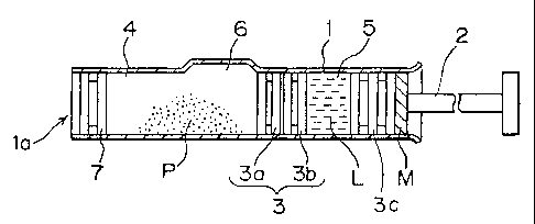
The cylindrical barrel 1 is uniformly cylindrical as a whole except
a bypass channel 6 defining the bypass portion to be described later and has
its
opposed ends fully opened.
CA 02200030 2005-08-22
-14-
The end slidable sealing member 3C mounted to the rod 2 is inserted
into this cylindrical barrel 1 from its rear end side as well as an
intermediate
slidable sealing member 3 is inserted therein so as to divide the interior of
the
barrel 1 into a first chamber 4 and a second chamber 5. This slidable sealing
member 3 is divided into a forward slidable sealing member 3a and a backward
slidable sealing member 3b. These forward slidable sealing member 3a and
backward slidable sealing member 3b may be in contact with each other or have
a predetermined space therebetween as illustrated. In order to provide such a
space therebetween, a suitable lug may be formed in at least one of the
opposed
surfaces of the forward slidable sealing member 3a and the backward slidable
sealing member 3b.
A sealing member 7 is mounted to the leading end opening portion
la of the cylindrical barrel 1. Incidentally, for example a cap with a needle
may
be mounted to the leading end portion of this cylindrical barrel 1 when we
need
injection as described later, or the needle may be mounted thereto by such a
known means as to attach a double-pointed needle to a holder member and make
its rear end pierce through the sealing member 7.
The first chamber 4 is charged with powder medicine P and the
second chamber 5 is charged with a dissolution liquid, a dispersion liquid or
various kinds of medicinal liquids L respectively. The bypass channel 6 is
formed
in a side wall of the first chamber 4 of the cylindrical barrel 1 so as to
have a
predetermined width and to be swelled or protruded outward. A length of this
bypass channel 6 in the axial direction of the cylindrical barrel 1 is set
longer by
a predetermined degree than a total length of both the forward slidable
sealing
member 3a and the backward slidable sealing member 3b. Further, a total length
CA 02200030 2005-08-22
-15-
of the slidable sealing members 3a, 3b and the end portion sealing member 3c
in
the axial direction is set longer by a predetermined degree than an axial
length of
the bypass channel 6. This length adjustment can be made readily by regulating
a length of the end slidable sealing member.
In the practical mode of the present invention having the
above-mentioned construction, similarly to the conventional one, both the
forward
slidable sealing member 3a and the backward slidable sealing member 3b are
advanced via a body of the liquid L within the second chamber 5 by pushing the
end slidable sealing member 3c mounted on the rod 2 (referred to as a plunger
member hereinafter) toward its leading end side and these reach the formation
position of the bypass channel 6 so that the first chamber 4 and the second
chamber 5 are put in communication with each other. Thereupon, the liquid L
within the second chamber S flows into the first chamber 4. After this flowing-
in
is completed and the leading end of the plunger member 3c is moved to the rear
end of the backward slidable sealing member 3b, this member 3b is directly
pushed to advance the forward and backward slidable sealing members 3a, 3b and
to stop the pushing at a position where at least a fore half portion of the
forward
slidable sealing member 3a reaches ahead of the leading end portion of the
bypass
channel 6 and at least a rear half portion of the sealing member 3c of the
plunger
member does not reach the bypass channel 6 to hold the slidable condition
relative
to the inner wall of the cylindrical barrel 1. Then, after the mixing and so
on are
completed by shaking the cylindrical barrel l, the injection liquid prepared
by the
dissolution, the dispersion or the mixing is injected through the needle
mounted
to the leading end of the barrel 1. Thereupon, the liquid leak preventing
element
M absorbs and holds the residual liquid within the bypass channel.
CA 02200030 2005-08-22
- 16-
Next, the procedures of the assembling of the syringe main body
including charging of the powder medicine, the dissolution liquid and so on in
the
above-mentioned practical mode of the present invention are shown in Figs. 2A
and 2B .
S First, as shown in Fig. 2A, the dissolution liquid, the dispersion
liquid or the medicinal liquid L is charged into the second chamber 5 and the
end
portion sealing member 3c is inserted therein on condition that the backward
slidable sealing member 3b is inserted into the cylindrical barrel 1. After
sterilization for the dissolution liquid, the dispersion liquid or the medical
liquid
L made by a steam heating on this condition, the inner surface of the first
chamber 4 is dried Llp. At this steam heating sterilizing treatment, the
dissolution
liquid, the dispersion liquid or the medicinal liquid L within the second
chamber
S containing an activation substance is treated at such a temperature as not
to
destroy the substance, for example at most 50 - 60 °C.
After that, as shown in Fig. 2B, the forward slidable sealing member
3a is inserted into the cylindrical barrel 1 through its leading end opening
portion
la on the previously sufficiently dried-up condition to be brought into
intimate
contact with the backward slidable sealing member 3b or at a position near
thereto
spaced apart a very short distance. After the powder medicine P is charged
into
the first chamber 4 through its leading end opening portion 1 a on that
condition,
the two-ingredient pre-filled syringe shown in Fig. 1 can be obtained by
mounting
the stationary sealing member 7 to the leading end opening portion la. In this
case, there may be employed either one of the rods 2 mounted originally or
mounted later.
CA 02200030 2005-08-22
-17-
In the above-mentioned assembling procedures, moisture tends to
attach to or penetrate the backward slidable sealing member 3b at the time of
steam heating sterilization of the dissolution liquid, the dispersion liquid
or the
medicinal liquid L within the second chamber 5, it is possible to prevent
transferring of the moisture to a side of the powder medicine P by inserting
the
dried-up forward slidable sealing member 3a and then charging the powder
medicine P into the first chamber 4 after steps of this steam heating
sterilization,
a drying-up and a cooling-down.
In a case of such a construction as to provide a space between the
forward and the backward slidable sealing members 3a, 3b, a time required for
moisture to enter the forward slidable sealing member 3a from a side of the
second chamber 5 through the backward slidable sealing member 3b in a stored
state after the assembly becomes longer, it becomes possible to elongate a
period
of time required for the moisture to reach the medicine on a side of the first
chamber 4.
Although it was already described that the above two-ingredient pre-
filled syringe according to the present invention is used on a condition that
the
needle is mounted to the leading end of the cylindrical barrel 1, there will
be
explained hereinafter more concrete structure examples of the needle mounting
element, the sealing member 7 at the leading end opening portion la of the
cylindrical barrel 1, the slidable sealing member 3a and so on.
[Examples]
Fig. 3 is a sectional view showing an example in which as the
sealing member 7 to be inserted into the leading end opening portion of the
cylindrical barrel 1 is used the slidable type one.
CA 02200030 2005-08-22
-18-
This example shows a barrel 1 wherein a cap 8 is mounted with the
needle onto a distal end thereof. The cap 8 has a needle 82 mounted to a tip
end
of a cup-shaped cap main body 81 and has such a construction that a groove 81a
communicating with the needle 82 is formed in the inner circumference of the
main body 81. Further, the main body 81 has a void space 81b which projects
toward the distal end side from the end opening portion la of the cylindrical
barrel
1 by a predetermined distance and into which the sealing member 7 can be
inserted.
Under such a condition, when flowing the dissolution liquid, the
dispersion liquid or other kinds of medicine liquids within the second chamber
5
into the first chamber 4 through the bypass channel 6 by pushing the rod 2 and
as
shown in Fig. 4, the sealing member 7 is moved into the void space of the main
body 81 of the cap 8 with the needle. When further pushing the rod 2 under
this
condition, the injection liquid within the first chamber 4 enters the needle
82
through the groove 81a formed in the main body 81 of the cap 8 and then is
injected. The cap 8 with the needle may be prepared at the time of injection
or
may be already mounted before the injection.
Instead of the above-mentioned construction, the sealing member 7
may be so constructed as to be spaced apart a short distance from the leading
end
of the cylindrical barrel 1 when the sealing member 7 is arranged within the
barrel
1 and stay at the leading end portion of the cylindrical barrel 1 when flowing
of
the liquid within the second chamber 5 into the first chamber 4 by the plunger
2
is completed. Since the fore and rear ends of the first chamber 4 are
completely
closed, even when the barrel 1 is shaken at the time of dissolving or
dispersing,
the liquid does not leak from anywhere.
CA 02200030 2005-08-22
-19-
Fig. 5 is a sectional view showing an example in which as the
sealing member 7 a stationary type one is used. In this type, a double-pointed
needle 10 is put at its rear end portion through the sealing member 7 so as to
project into the first chamber 4 by mounting the cap 9 serving also as a
needle
holding member to the leading end portion of the cylindrical barrel 1 and
inserting
the double-pointed needle 10 through this cap 9 to a predetermined position.
In this construction, since the needle is soon communicated with the
first chamber 4 by mounting the double-pointed needle 10, it becomes possible
to
inject the injection liquid within the first chamber 4 directly through the
interior
of the double-pointed needle 10 similarly to the above-mentioned one.
In the type of employing the double-pointed needle 10, since the rear
end portion of the needle 10 passes through the sealing member 7 to enter the
first
chamber 4, as shown in Fig. 5, it becomes possible to decrease a quantity (a
loss
quantity) of the residual injection within the cylindrical barrel 1 at the
time of
injection by previously forming in the end face of the sealing member 7 on the
side of the first chamber 4 a concave portion 7a which is capable of receiving
a
projecting length of the needle.
In the two-ingredient pre-filled syringe, on a condition that the liquid
L within the second chamber 5 is nearly completely flowed into the first
chamber
4 by pushing the plunger rod 2 prior to an actual injection so that two-
ingredients
are dissolved, dispersed or mixed uniformly within the first chamber 4. On a
condition that the liquid doesn't flow out yet from the distal end of the
barrel l,
it is necessary to stop the plunger member once and shake the syringe well. At
the time of shaking working, in order to prevent the flowing-out of the
dissolution
liquid or the dispersion liquid transferred to the first chamber 4 to the
interior of
CA 02200030 2005-08-22
-20-
the original second chamber 5, namely to the proximal or rear portion of the
cylindrical barrel 1 beyond the sealing member 3c of the plunger member after
the reverse flowing through the bypass channel 6, this plunger member should
be
stopped once at a suitable position.
After the above-mentioned working, when the plunger 3c is further
advanced, the medicine liquid is injected through the needle 82. When the rear
end of the end sealing member 3c passes the bypass channel 6, the residual
liquid
within the bypass channel 6 tends to leak backward. Therefore, according to
the
present invention, the liquid leak preventing element M is arranged at the
rear end
of the end sealing member 3c.
Figs. 6 and 7 show an embodiment in which such operations are
simplified.
In the example illustrated in Fig. 6, a convex portion 101 projecting
circumferentially inward beyond the inner peripheral surface of the
cylindrical
barrel 1 is formed in the inner peripheral surface of a finger grip 100
mounted to
the proximal or rear end portion of the cylindrical barrel 1, and a plurality
of lugs
201 are formed in the rod 2 along the same circumference at a predetermined
position in the axial direction of the rod. The formation position of each lug
201
in the axial direction of the rod 2 is set to such a position that the lugs
201 are
brought into contact with the convex portion 101 of the finger grip 100 on a
condition that the leading end face of the forward slidable sealing member 3a
reaches ahead of the leading end portion of the bypass channel 6 as well as
the
rear end face of the backward slidable sealing member 3b is brought into
contact
with the leading end surface of the end sealing member 3c and further the rear
half portion of the end sealing member 3c doesn't enter the bypass channel 6
to
CA 02200030 2005-08-22
-21 -
keep the sliding state relative to the inner wall of the cylindrical barrel 1.
A
distance between the axis of the rod 2 and a point of each lug is a little
larger than
an inner diameter of the convex portion 101 of the finger grip 100. Further, a
material of the finger grip 100 is a flexible one, for example like a
synthetic resin.
S According to the above construction, when the rod 2 is pushed in
from a not-using condition illustrated in Fig. 6A, the forward slidable
sealing
member 3a is staying near the leading end of the bypass channel 6 during the
transferring of the liquid as shown in Fig. 6B. When it is further pushed in,
the
rod 2 and the end sealing member 3c are stopped once due to a resistance
produced by the contact between the lugs 201 and the convex portion 101 as
shown in Fig. 6C.
On one hand, in an example shown in Figs. 7A to 7F, the convex
portion 101 is similarly formed in the inner peripheral surface of the finger
grip
100 mounted to the rear end portion of the cylindrical barrel 1. As shown in
the
axial view of Fig. 7B, a plurality of cut-out grooves 102 are formed in this
convex
portion 101 as well as the same number of blades 202 are formed in the rod 2.
A distance from the center of the rod 20 to the point of each blade 202 is
larger
than the inner diameter of the convex portion 101 of the finger grip 100 and
shorter than a distance from the center of the finger grip 100 to the bottom
of
each cut-out groove 102. A position of the leading end of each blade 202 is so
set that the blades 202 are brought into contact with the rear end face of the
finger
grip 100 on a condition that the leading end face of the forward slidable
sealing
member 3a reaches ahead of the leading end portion of the bypass channel 6
owing to the pushing by the end sealing member 3c as well as the rear end face
of the backward sealing member 3b and the leading end face of the plunger 3c
are
CA 02200030 2005-08-22
-22-
in contact with each other and further the rear half portion of the end
sealing
member 3c doesn't enter the bypass channel 6 to keep the sliding condition
relative to the inner wall of the barrel 1.
In the above-mentioned construction, in a pre-use condition
illustrated in Fig. 7A, the rod 2 is inserted into the cylindrical barrel 1 in
such a
condition that each blade 202 doesn't take the same position as the formation
position of the cut-out groove 102 of the finger grip 100 as shown in Fig. 7C.
At
the time of usage, first the plunger with the rod 2 is pushed with the state
of Fig.
7C. Thereby, the forward slidable sealing member 3a stops at the leading end
of
the bypass channel 6 during the transferring of the liquid as shown in Fig.
7D.
When it is further pushed in, as shown in Fig. 7E, the blades 202 are brought
into
contact with the rear end face of the finger grip 100 to stop the plunger at
that
time. Since the liquid within the second chamber 5 is poured completely into
the
first chamber 4 as mentioned above under that condition as well as the reverse
flowing through the bypass channel 6 is prevented, the two ingredients are
uniformly dissolved, dispersed or mixed by shaking the syringe on that
condition.
After that, when each blade 202 is made to take the formation position of each
cut-out groove 102 by turning the rod 2, since the pushing-in of the whole rod
becomes possible as shown in Fig. 7F, the injection liquid after the
dissolution,
the dispersion or the mixing can be injected to a living body.
As shown in Fig. 7F, the injection liquid after the dissolution, the
dispersion or the mixing can be injected to a living body.
By the way, instead of employing the above construction illustrated
in Fig. 6 or Fig. 7, it is effective merely to provide a line marking in the
outer
peripheral surface or the inner peripheral surface of the cylindrical barrel 1
along
CA 02200030 2005-08-22
26456-96
-23-
its circumferential direction at a predetermined position in front of the
leading end
portion of the bypass channel 6, for example at a forward position by a
distance
of about 2 mm from the leading end portion of the bypass channel 6. That is,
when the plunger is pushed in order that the leading end face of the forward
slidable sealing member 3a does not go beyond the marking, the liquid within
the
second chamber 5 is flowed nearly completely into the first chamber 4 and then
the syringe may be shaken on that condition.
In each already described embodiment, the forward and the
backward slidable sealing members 3a, 3b or the end slidable sealing member 3c
may be constructed by a plurality of ribs projecting circumferentially from
the
outer peripheral surface thereof respectively so as to hold a liquid-tightness
between the first chamber 4 and the second chamber 5 or a liquid-tightness
between the second chamber 5 and the outside of the barrel 1, and in addition,
to
keep their slidabilities within the barrel 1. In such a construction, when the
respective slidable sealing members 3a, 3b or the slidable sealing member 3c
pass
over the bypass channel 6 by pushing the rod 2, the liquid remaining within
the
bypass channel 6 enters an annular concave portion formed between the
respective
circular ribs of the respective sealing members 3a, 3b or the sealing member
3c
of the plunger, resulting in loss of the injection liquid. In order to solve
this
problem, those concave portions may be made shallower in such a degree as not
to worsen the slidability of the sealing member. But, a countermeasure for
further
lessening the loss quantity will be described hereinafter.
Fig. 8 is a sectional view of an embodiment to which such a
countermeasure is applied.
CA 02200030 2005-08-22
26456-96
-24-
A plurality of circular ribs 300 are formed in the forward slidable
sealing member 3a, the backward slidable sealing member 3b and the end sealing
member 3c respectively and a plurality of longitudinal ribs 301 are formed
between the respective circular ribs so as to have nearly the same height as
those
of these ribs. Void spaces formed between the respective circular ribs 300 are
partitioned by these respective longitudinal ribs 301 to a plurality of
smaller void
spaces respectively.
In this embodiment, the four longitudinal ribs 301 are formed within
the respective void spaces of the respective sealing members 3a, 3b, 3c at
such
positions as to divide the respective outer circumferences equally into four
portions, so that the respective void spaces between the circular ribs 300 are
divided equally into four portions (refer to Fig. 9).
Such a construction, when the forward slidable sealing member 3a,
the backward slidable sealing member 3b and the end slidable sealing member 3c
pass over the bypass channel 6 owing to the pushing of the rod 2, makes the
injection liquid enter any one of the small void spaces partitioned by the
longitudinal ribs 301 of the void spaces between the respective circular ribs
300
through this bypass channel 6. But, the injection liquid cannot enter the
adjacent
small void spaces because of the existing of the longitudinal ribs 301, so
that the
residual injection liquid within the void spaces of the respective sealing
members
decreases to about 1/4 in comparison with the case in which only the circular
ribs
300 are provided.
The number of the longitudinal ribs 301 arranged within the
respective void spaces between the circular ribs 300 is not limited to four
but can
be selected optionally to at least two. It becomes possible to decrease the
loss
CA 02200030 2005-08-22
26456-96
-25-
quantity of the injection liquid as the number thereof increases more, but to
the
contrary, since the slidability of each sealing member lowers accordingly
thereto,
it is preferable to select the suitable number in consideration of both of
them. The
longitudinal ribs 301 may be formed only in the forward and the backward
S slidable sealing members 3a, 3b.
In the r~spectiv~ circular ribs 300 and longitudinal ribs 301 of the
forward and the backward slidable sealing members 3a, 3b and the sealing
member 3c of the plunger, their axial configurations may be formed like so-
called
a crowing having a swell which is suitably curved axially to decrease a
frictional
resistance relative to the cylindrical barrel 1 instead of linearly along the
inner
wall surface of the cylindrical barrel 1 as illustrated.
The above-mentioned liquid-absorbent element M may be formed
from the cylindrical liquid-absorbent member R slidable relative to the
cylindrical
barrel and detachably mounted to the leading end portion of the plunger rod.
This liquid-absorbent material R is manufactured by stamping a liquid-
absorbent
material sheet in a predetermined configuration, which may be selected from
the
group consisting of polyvinylformal, polyester fiber, pulp, polyester fiber
containing pulp, polyester fiber containing acetate fiber, acetate fiber,
cellulose
sponge, polyvinyl alcohol sponge and liquid-absorbent resin and may be
impregnated by dipping with a water-holding and liquid-absorbing accelerator,
which may be selected from the group consisting of glycerine, propylene
glycol,
polyethylene glycol, D-sorbitol, polyoxyethylene cetyl ether, and benzyl
alcohol.
It may be made cylindrical by stacking the above-mentioned disk-shaped liquid-
absorbent materials D as shown in Fig.lS. The liquid-absorbent material may be
impregnated with an antimicrobial active agent selected from benzalkonium
CA 02200030 2005-08-22
-26-
chloride, benzethonium chloride, dodecyldiamino-ethylglycine,
dodecyldimethylbenzylammonium chloride, polyhexa-methylenebiguanide and
alkyldiaminoethylglycine hydrochloride.
In this case, as shown in Fig. 23, since the cylindrical liquid
s absorbent material R is longer in its total length in the advancing
direction (usually
at least 10 mm in the total length) in comparison with the disk-shaped liquid
absorbent material D as shown in Fig. 15, the sufficient liquid-absorbing and
holding can be attained even when a dropping timing of the residual liquid
gets
delayed a little at the time of the passing of the cylinder over the bypass
channel.
Further, when the end portion slidable sealing member is pushed completely,
the
cylindrical liquid-absorbent material R is usually pushed in forward beyond
the
bypass channel. But, especially as shown in Fig. 24, when its rear end can
stay
there so as to pass over the bypass channel, a function for preventing the
leaking
of the residual liquid is large. In the above embodiment, the same component
members as those in Fig. 6 are designated by the same numbers, and the
explanations thereof are omitted.
Although the present invention has been fully described by way of
examples with reference to the accompanying drawings, it is to be noted here
that
various changes and modifications will be apparent to those skilled in the
art.
Therefore, unless such changes and modifications otherwise depart from the
spirit
and scope of the present invention, they should be construed as being included
therein.