Sélection de la langue

Search

Sommaire du brevet 2200647 

Énoncé de désistement de responsabilité concernant l'information provenant de tiers

Une partie des informations de ce site Web a été fournie par des sources externes. Le gouvernement du Canada n'assume aucune responsabilité concernant la précision, l'actualité ou la fiabilité des informations fournies par les sources externes. Les utilisateurs qui désirent employer cette information devraient consulter directement la source des informations. Le contenu fourni par les sources externes n'est pas assujetti aux exigences sur les langues officielles, la protection des renseignements personnels et l'accessibilité.

Disponibilité de l'Abrégé et des Revendications

L'apparition de différences dans le texte et l'image des Revendications et de l'Abrégé dépend du moment auquel le document est publié. Les textes des Revendications et de l'Abrégé sont affichés :

  • lorsque la demande peut être examinée par le public;
  • lorsque le brevet est émis (délivrance).
(12) Demande de brevet: (11) CA 2200647
(54) Titre français: CAPTEUR DE CHALEUR POUR ESSIEUX D'ENSEMBLE ROUTIER
(54) Titre anglais: HEAT SENSOR FOR TRACTOR TRAILER AXLE
Statut: Réputée abandonnée et au-delà du délai pour le rétablissement - en attente de la réponse à l’avis de communication rejetée
Données bibliographiques
(51) Classification internationale des brevets (CIB):
  • G01K 13/08 (2006.01)
  • B60Q 09/00 (2006.01)
  • B60T 08/171 (2006.01)
(72) Inventeurs :
  • SWADZBA, DANIEL R. (Canada)
  • WOSING, RUDY (Canada)
(73) Titulaires :
  • DANIEL R. SWADZBA
  • RUDY WOSING
(71) Demandeurs :
  • DANIEL R. SWADZBA (Canada)
  • RUDY WOSING (Canada)
(74) Agent:
(74) Co-agent:
(45) Délivré:
(22) Date de dépôt: 1997-03-21
(41) Mise à la disponibilité du public: 1998-09-21
Licence disponible: S.O.
Cédé au domaine public: S.O.
(25) Langue des documents déposés: Anglais

Traité de coopération en matière de brevets (PCT): Non

(30) Données de priorité de la demande: S.O.

Abrégés

Abrégé français

Cette invention concerne une méthode et un dispositif de surveillance de la température des paliers d'essieux de remorques portant les ensembles moyeu-roue-pneumatique du véhicule. Elle fait appel à un capteur de chaleur placé en contact avec la région visée, qui se trouve entre le moyeu et la fusée d'essieu, et relié électriquement à un indicateur ou moyen d'affichage situé, de préférence, devant le conducteur de l'ensemble routier. Lorsque la température dépasse un seuil prédéterminé, l'indicateur alerte le conducteur qui peut dès alors quitter la route pour laisser refroidir et repartir immédiatement vers un endroit approprié pour effectuer les réparations qui s'imposent.


Abrégé anglais


A method and apparatus to monitor the temperature of
a bearing region of a trailer axle-spindle about which
a wheel hub and drum assembly (commonly known as
tractor tires) rotating so that the wheels thereof
traverse the roadway over which the trailer is pulled.
In the bearing region bounded between the hub drum
assembly and the axle-spindle, there is provided a
thermal sensor which is in thermal contact with the
bearing region and the sensor is electrically connected
to an indicator or monitoring means, preferably located
in front of a driver driving the lorry pulling the
trailer. When the temperature of the bearing region
exceeds a predetermined threshold temperature, the
indicator advises the driver that this threshold
temperature has been exceeded and the driver can then
pull the rig or lorry off the road to let the bearing
region cool and then drive the rig to a convenient
place for servicing.

Revendications

Note : Les revendications sont présentées dans la langue officielle dans laquelle elles ont été soumises.


The embodiments of the invention for which an
exclusive property or privilege is claimed are defined
as follows:
1. A method of measuring the temperature at a
bearing interface thermally in contact with a spindle
attached to at least one end of an axle carrying with
drum-hub assembly adapted for rotating on the bearing,
the assembly carrying tire rim and tires by which the
trailer is traversed with the ground comprising the
steps of;
(a) placing a thermo couple in thermal contact
with the bearing;
(b) monitoring the temperature of the bearing
up to a predetermined upper threshold temperature above
which thermal metal fatigue can ensue; and,
(c) activating a warning indicator when the
threshold temperature has been reached.
2. A temperature responsive device adapted to
monitor a threshold temperature of a bearing region
disposed between an axle-spindle and a hub and drum
sub-assembly, the sub-assembly carrying about its outer
perimeter tire rims adapted for engagement of tires
which traverse the ground and upon which a trailer
carried by the axle is traversed comprising:
(a) an axle-spindle defining, on its outer
perimeter, an annular bearing region;
(b) a hub and drum assembly defining an inner
bore adapted to rotatingly travel within the annular
bearing region;
(c) a thermal sensor thermally in contact with
the bearing region; and,
(d) monitoring means electrically attached to
the thermal sensor and responsive to a threshold
temperature including an indicator means therefor.

3. The temperature responsive device as claimed in
claim 2, wherein the thermal sensor is located within a
bore defined by the axle-spindle and co-axial with the
bearing region.
4. The temperature responsive device as claimed in
claim 2, wherein the thermal sensor is positioned in a
diametrical plane of the annular bearing region.
5. The temperature responsive device as claimed in
claim 4, wherein the bearing region is defined by an
inner annular bearing and an outer annular bearing.
6. The temperature responsive device as claimed in
claim 4 or 5, wherein the sensor is in the diametrical
plane of the outer annular bearing.

Description

Note : Les descriptions sont présentées dans la langue officielle dans laquelle elles ont été soumises.

- ~Où647
.
llEAT SENSOR FOR TRACTOR TRAILER AXLE
This invention relates to a tractor trailer axle
heat sensor adapted to sense the temperature at a
rotating bearing interface disposed between a trailer
axle spindle and a hub-drum assembly which carries tire
rims and tires.
BACKGROUND TO TIIE INVENTION
In lorries; or, large tractor trailers commonly used
in North America, the trailers or semi-trailers
generally use tandem double wheels on either side, at
the rear; sometimes also in the centre.
Over the past short while wi~h the increase of cargo
loads carried by such trailers during transit across
the highway network throughout North America and
particularly in the Province of Ontario, Canada, many
accidents have occurred due to the fact that the drum-
hub assembly flies off the trailer axle spindle due to
fatigue of the studs or nuts holding the hub-drum
Z0 assembly to the axle spindle. Severe damages to other
vehicles occur and in some instances, even death to
motorists who travel behind, in front, or along the
opposite travelling lanes to the truck that is having
these difficulties.
THE INVENTION
It is an object of the invention to provide a
warning device, to the operator of the truck pulling a
trailer, of a temperature increase in the axle spindle-
bearing-hub and drum assembly interface for each wheel
on the trailer. The hub-drum assembly is secured onto
the axle spindle generally by a hub-drum locking
assembly which threadingly engages over a threaded
portion of the spindle end to hold the hub-drum sub-
assembly on the spindle. A pair of annular roller
bearings are provided between the hub-drum assembly and
the spindle to allow free rotation of that assembly
about the spindle during travel. Generally there are
two bearings, an inner larger bearing and an outer
smaller bearing. If either of these bearings are not

2200647
.
adequately maintained, they tend to dry up and seize
and the temperature of the bearing region is increased,
as is the axle spindle itself and the rotational bore
define~ ~y the hub-drum assembly. When the temperature
at the bearing region increases beyond either the
fatigue temperature of the bearing itself or, of the
spindle axle, the whole hub-drum assembly dislodges and
can fly off and away from the trailer. This phenomenum
has been referred to in recent literature as "run-away
truck wheels". When the lorry is travelling at speeds
of lOOkmh or more, the momentum of such run-away truck
wheels will travel great distances, sometime cross the
meridian of the highway into oncoming traffic. In
other instances, the retaining nuts loosen or melt off
creating run-away truck wheels. Fatigue generally
occurs when the temperature of the bearing interface
rises above 270 F and when it reaches approximately
290 F, metal fatigue can set in to the adjoining
regions of the hub-drum assembly and of the axle
spindle.
It is an object of this invention to monitor the
temperature at the spindle-axle/hub-drum interface and
to provide the driver of the truck pulling the trailer
having such sensored wheels an indication that the
temperature has risen above 270 F so that the rig can
be taken off the road; then servicing take place.
The invention contemplates a method of measuring the
temperature at a bearing interface thermally in contact
with a spindle attached to at least one end of an axle
carrying with drum-hub assembly adapted for rotating
on the bearing, the assembly carrying tire rim and
tires by which the trailer is traversed with the ground
comprising the steps of placing a thermo couple in
thermal contact with the bearing, monitoring the
temperature of the bearing up to a predetermined upper
threshold temperature above which thermal metal fatigue
can ensue and, activating a warning indicator when the
threshold temperature has been reached.

2200647
Additionally, the invention contemplates a
temperature responsive device adapted to monitor a
threshold temperature of a bearing region disposed
between an axle-s~indle and a hub and drum sub-
assembly, the sub-assembly carrying about its outer
perimeter tire rims adapted for engagement of tires
which traverse the ground and upon which a trailer
carried by the axle is traversed comprising an axle-
spindle defining, on its outer perimeter, an annular
bearing region, a hub and drum assembly defining an
inner bore adapted to rotatingly travel within the
annular bearing region, a thermal sensor thermally in
contact with the bearing region and, monitorin~ means
electrically attached to the thermal sensor and
responsive to a threshold temperature including an
indicator means therefor. Preferably, thermal sensor
is located within a bore defined by the axle-spindle
and co-axial with the bearing region, preferably
located between the diametrical plane of the ends of
the bearing region and as described in the preferred
embodiment in the diametrical plane of an outer annular
bearing where there are two annular bearings defining
the bearing region.
BRIEF DESCRIPTION OF THE DRAWINGS
The invention will now be described by way of
example and in reference to the accompanying drawings
in which:
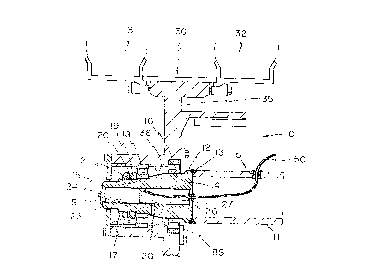
Figure 1 is cross-sectional view of a portion
of an axle with spindle according to the invention;
Figure 2 is a block circuit diagramme of the
electronic circuit according to the invention for
measuring the temperature of each spindle axle-bearing
interface.
Referring to Figure 1, (10) is a cross-sectional
view of a modified conventional trailer hollow axle
with spindle that is generally used in North America
for the purposes of carrying hub-drum assemblies

L~oo647
carrying wheels of a tractor trailer. It consists of a
hollow cylindrical shaft (11) that is the axle to the
trailer (not shown) and extends from one side of the
trailer to the opposite side, only the left-hand
portion of the hollow axle (11) is indicated. It is
welded, at its end, to a hollow, stepped cylindrical or
swaged member, referred to as an axle-spindle (12) by
an annular weld ( 13) . The spindle ( 12) has a first
outer annular step (14) to accommodate an inner larger
diameter cylindrical roller bearing ( 16) and then steps
into a smaller diameter outer annular step ( 15) which
accommodates an outer smaller annular roller bearing
(18). The end of the spindle ( 12) is outwardly
threaded at (17). The outer bearing (18) is held in
position by a double locking nut and washer assembly
(19,20,21) which is constrained by the threaded nuts
(19,21) into locking position over the outer threads
(17) against the outer surface of the outer smaller
bearing (18). Typically, a wheel hub and drum assembly
(30,35) has an outer radial flange ( 35) integral with a
hub drum portion (not referenced) which defines an
inner bore (36). The flange (35) carries rim (30) and
inner and outer tandem wheels ( 31) and ( 32) that are
attached to the peripheral of the flange ( 35) by
conventional means. The inner bore ( 36) is profiled in
a manner to allow the hub drum assembly ( 30,35) to
freely rotate over the bearings (16) and (18) in a
fashion conventionally known. The spindle (15) has an
internal bore (23) and is generally fitted with an
overcovering frost plug ( 24) to isolate contaminates
from entering into the bore ( 23) that may be partially
filled with a lubricant such as grease or oil.
Conventionally, the bore (23) terminates at an inner
end surface ( 26) but according to the invention, a
sealed aperture (27) is drilled therein to provide
access for the passage, in a sealing fashion, of an
electrical conducting wire (51), part of a circuit
(50), see Figure 2, serially connected to a battery (B)

- 2200647
-
and an indicator (I) and a thermal sensor (S)
preferably located within the bore (23). The sensor
(S) is in the thermal contact with that bearing region
defined by the diametrical planes of the roller
bearings (16) and (18), thus preferably located co-
incident to the diametrical plane of the outer smaller
bearing (18) and confined within the bore (23).
Preferably, the indicator (I) is placed in the driver
cabin and is visible to the driver of the lorry and the
indicator (I) remains on when the temperature measured
by the sensor (S) is below the upper threshold
temperature range, 270 F to 290 F. Thus, any time the
ignition o~ the lorry is activated the indicator (I)
will light indicating that the sensor (S) is working
properly. When the threshold temperatures is exceeded,
the indicator light (I) extinguishes indicating that
the bearing region (16,18) temperature has exceed
threshold temperature. Although the preferred range is
270 F to 290 F, depending upon the materials used for
the hub and drum assembly (30,35) and their respective
physical properties, the threshold temperature range
can be varied.

Dessin représentatif
Une figure unique qui représente un dessin illustrant l'invention.
États administratifs

2024-08-01 : Dans le cadre de la transition vers les Brevets de nouvelle génération (BNG), la base de données sur les brevets canadiens (BDBC) contient désormais un Historique d'événement plus détaillé, qui reproduit le Journal des événements de notre nouvelle solution interne.

Veuillez noter que les événements débutant par « Inactive : » se réfèrent à des événements qui ne sont plus utilisés dans notre nouvelle solution interne.

Pour une meilleure compréhension de l'état de la demande ou brevet qui figure sur cette page, la rubrique Mise en garde , et les descriptions de Brevet , Historique d'événement , Taxes périodiques et Historique des paiements devraient être consultées.

Historique d'événement

Description Date
Inactive : CIB de MCD 2006-03-12
Demande non rétablie avant l'échéance 2001-03-21
Le délai pour l'annulation est expiré 2001-03-21
Réputée abandonnée - omission de répondre à un avis sur les taxes pour le maintien en état 2000-03-21
Inactive : Supprimer l'abandon 1999-02-05
Inactive : Demande ad hoc documentée 1999-02-05
Inactive : Abandon. - Aucune rép. à lettre officielle 1999-01-06
Demande publiée (accessible au public) 1998-09-21
Inactive : CIB attribuée 1997-07-23
Inactive : CIB en 1re position 1997-07-23
Modification reçue - modification volontaire 1997-06-06

Historique d'abandonnement

Date d'abandonnement Raison Date de rétablissement
2000-03-21

Taxes périodiques

Le dernier paiement a été reçu le 1999-02-12

Avis : Si le paiement en totalité n'a pas été reçu au plus tard à la date indiquée, une taxe supplémentaire peut être imposée, soit une des taxes suivantes :

  • taxe de rétablissement ;
  • taxe pour paiement en souffrance ; ou
  • taxe additionnelle pour le renversement d'une péremption réputée.

Les taxes sur les brevets sont ajustées au 1er janvier de chaque année. Les montants ci-dessus sont les montants actuels s'ils sont reçus au plus tard le 31 décembre de l'année en cours.
Veuillez vous référer à la page web des taxes sur les brevets de l'OPIC pour voir tous les montants actuels des taxes.

Historique des taxes

Type de taxes Anniversaire Échéance Date payée
Taxe pour le dépôt - petite 1997-03-21
TM (demande, 2e anniv.) - petite 02 1999-03-22 1999-02-12
Titulaires au dossier

Les titulaires actuels et antérieures au dossier sont affichés en ordre alphabétique.

Titulaires actuels au dossier
DANIEL R. SWADZBA
RUDY WOSING
Titulaires antérieures au dossier
S.O.
Les propriétaires antérieurs qui ne figurent pas dans la liste des « Propriétaires au dossier » apparaîtront dans d'autres documents au dossier.
Documents

Pour visionner les fichiers sélectionnés, entrer le code reCAPTCHA :


Pour visualiser une image, cliquer sur un lien dans la colonne description du document. Pour télécharger l'image (les images), cliquer l'une ou plusieurs cases à cocher dans la première colonne et ensuite cliquer sur le bouton "Télécharger sélection en format PDF (archive Zip)" ou le bouton "Télécharger sélection (en un fichier PDF fusionné)".

Liste des documents de brevet publiés et non publiés sur la BDBC .

Si vous avez des difficultés à accéder au contenu, veuillez communiquer avec le Centre de services à la clientèle au 1-866-997-1936, ou envoyer un courriel au Centre de service à la clientèle de l'OPIC.


Description du
Document 
Date
(aaaa-mm-jj) 
Nombre de pages   Taille de l'image (Ko) 
Abrégé 1997-03-20 1 27
Description 1997-03-20 5 249
Revendications 1997-03-20 2 64
Dessins 1997-03-20 1 29
Revendications 1997-06-05 2 89
Dessin représentatif 1998-09-24 1 12
Avis de rappel: Taxes de maintien 1998-12-21 1 118
Avis de rappel: Taxes de maintien 1999-12-21 1 121
Courtoisie - Lettre d'abandon (taxe de maintien en état) 2000-04-17 1 182
Deuxième avis de rappel: taxes de maintien 2000-09-24 1 118
Avis de rappel: Taxes de maintien 2000-12-26 1 121
Correspondance 1998-10-01 1 21
Taxes 1999-02-11 1 72
Correspondance 1997-04-14 4 117