Note : Les descriptions sont présentées dans la langue officielle dans laquelle elles ont été soumises.
CA 02201014 2004-07-27
- ( -
s
Process and reactor for carrying out conversions with catalysts suspended
in liquids, and reactor for this purpose .
io
The present invention relates to a process for carrying out
catalytic reactions, in which a catalyst is suspended in a liquid phase. This
phase may already contain a liquid or suspended solid reactant. Also
is frequently present is a gas phase, from which reactants are dissolved in
the
liquid phase. Typical reactions of this type are oxidations and
hydrogenations.
Inter alia, bubble columns and stirred containers are suitable for carrying
out such reactions. The technology for suspension reactions is described in
Zo detail in Ullmanns Encyclopadie der technischen Chemie, 4th Edition, 1973,
Volume 3, pages 494 to 518. The basic problem of such reactions is to
ensure sufficient contact between the reactants and the catalyst particles
which
are suspended in the liquid phase.
Suspension reactors require the supply of mechanical energy, which is
Zs introduced, for example, by means of stirrers, jets or ascending gas
bubbles,
in order to suspend the solid particles. However, increasing this mechanical
energy supply beyond the magnitude required for suspending does not lead to
a significant improvement in the mass transfer between the liquid and the
suspended solid particles, since the achievable relative velocity exceeds the
CA 02201014 2004-07-27
-2-
sedimentation rate only to an insignificant extent. The use of catalyst
particles having larger particle sizes (from 1 to 10 mm) has been proposed
for increasing this relative velocity, in particular in fluidized bed
processes.
Although these larger particles have the desired velocity relative to the
s surrounding liquid, their smaller surface area per unit volume on the other
hand limits the conversion. The two effects frequently compensate one
another so that the problem of increasing the conversion is not solved.
Higher relative velocities can be achieved only by dispensing with the
suspension ~ procedure in fixed-bed reactors. Instead of fixed beds, it is
also
to possible to coat metal sheets or fabric with catalyst material, over which
the
liquid or gaseous phase flows. Such reactors are described in EP 068 862,
EP 201 614 and EP 448 884. However, a disadvantage of these reactors is
that the catalyst material can be regenerated only by replacing the coated
components. This is expensive and, when there is a risk of contamination
is of the catalyst material by impure reactants, leads to expensive
precautions,
for example ultrapurification of the starting materials.
It is an object of the ,present invention to provide a process for car-
rying out catalystic suspension reactions: of the type described,
having a higher space-time yield.
zo We have found that this object is achieved by the process described in
the claims. In this process for carrying out catalytic reactions in a reactor
which contains a liquid phase in which at least one catalyst is suspended,
and which may additionally contain a gas phase, the liquid phase and, if
present, the gas phase are fed, at least partly, ie. with ~at least a part of
is their volume or along a part of their route, through an apparatus having
orifices or channels in the reactor, the hydraulic diameter of which orifices
or channels is from 0.5 to 20 mm, preferably from 1 to 10 mm,
CA 02201014 2004-07-27
-3-
particularly preferably from 1 to 3 mm. Reactants may be introduced either
as liquid, as solid or as gas and may be dissolved in the liquid. In the
present invention, the state of aggregation in which the reactants are fed in
is in principle unimportant. The hydraulic diameter is defined as the
s quotient of 4 times the cross-section of the orifice and its circumference.
The choice of the channel width which is ideal in the specific case depends
in particular on the viscosity of the liquid passed through, the size of the
suspended particles and the presence and type of a gas phase. The channel
widths must be larger the more viscous the liquid. In the case of liquids
to having dynamic viscosities of from 10 to 200 Ns/m2, hydraulic diameters of
from 1 to 3 mm are optimum. In the presence of a gas phase, it is
advisable to increase the channel diameter by from 10 to 50% .
In the novel process, the catalyst particles execute a greater
movement relative to the liquid phase because they are decelerated relative to
is the surrounding liquid in the narrow orifices and channels.. ~ This
deceleration
may be caused by collisions with the channel walls or by brief retention of
the particles on rough wall surfaces. In the novel process, suspended
catalyst particles having a mean particle size of from 0.0001 to 2 mm, pre-
ferably from 0.001 to 0.1 mm, more preferably from 0.005
20 to 0.05 mm, are be .used. These particles with their large surface area per
unit volume give good results because, owing to the passage through the
narrow baffles, they can execute movements relative to the liquid. The
result is that substantially higher space-time yields can be achieved. An
experiment showed that even small relative movements of the catalyst
is particles or deceleration of only a small proportion of the catalyst
particles
lead to acceleration of the reaction.
The apparatus having orifices or channels for carrying out the feed
~20i0;~
-4-
phase may consist in a bed, a knitted fabric, an open-cell foam structure,
preferably of plastic (eg. polyurethane or melamine resin) or ceramic, or a
packing element as already known in principle, ie. in terms of its geometric
shape, from distillation or extraction technology. Such packing elements,
s which have the advantage of a small pressure loss, are, for example, wire
mesh packings of the designs Montz A3 and Sulzer BX, DX and EX. For
the purposes of the present invention, however, the packings have in
principle a hydraulic diameter which is substantially smaller, usually by a
factor of from 2 to 10, than comparable baffles in the area of distillation or
io extraction technology. Wire mesh packings are particularly advantageous.
This is presumably due to the fact that a part of the suspension does not
follow the channels formed but passes through the mesh. Instead of mesh
packings, packings of other woven, knitted or felted liquid-permeable
materials can also be used in the present invention. In further suitable
~s packings, flat metal sheets, preferably without perforations or other large
orifices, are used, for example based on the designs Montz B 1 and Sulzer
Mellapak. Packings of expanded metal, for example packings of the type
Montz BSH, are also advantageous. Here too, orifices, such as perforations,
must be kept appropriately small. What is decisive for the suitability of a
Zo packing in the present invention is not its geometry but the orifice sizes
or
channel widths in the packing which are formed for the flow.
A preferred process is one in which the liquid phase and, where
relevant, the gas phase are fed through orifices or channels whose wall
materials have surface roughnesses of from 0.1 to 10, preferably from 0.5 to
zs 5, times the mean particle size of the suspended catalyst particles. The
roughness of the orifices or channel walls results in particularly good
deceleration and hence relative movement of the suspended catalyst particles.
CA 02201014 2004-07-27
These are presumably briefly held on the wall surfaces so that they enter the
liquid stream again only after a delay. In the specific case, the preferred
roughness of the material used depends on the size of the suspended catalyst
particles.
s In a preferred process, the liquid phase or the liquid/gas phase is fed
through orifices or channels having metallic wall materials whose surfaces
have a center .line average value Ra according to DIN 476811 of from 0.001
to 0.01 mm. Such metallic surfaces may be produced, for example, by
thermal treatment of steels, for example Kanthal, in an oxygen atmosphere.
io Thus, not only macroscopic but also microscopic roughnesses are effective
for the purposes of the present invention.
In -a preferred process, the liquid phase is fed through the apparatus
having orifices and channels at an empty tube velocity of from about 50 to
300, preferably from 150 to 200, m3lmZh. When a gas phase is
~s simultaneously present, its empty tube velocity is preferably from 5 to
300,
particularly preferably from 100 to 200, m3/m2h.
According to the invention, a reactor for carrying out catalytic reactions,
is also provided:
This reactor has means for feeding in and removing a liquid phase or
Zo suspension. If required, the reactor also has further feeding and removal
means for a gas phase. The reactor contains at least one apparatus having
orifices and channels which have a hydraulic diameter of from 0.5 to 20
mm, preferably from 1 to 10 mm, particularly preferably from 1 to 3 mm,
the apparatus being installed and arranged in the reactor in such a way that
as the liquid phase and, where relevant, also the gas phase are fed, at least
partly, through the orifices and channels during the reaction. Consequently,
the more intensive movement of the liquid phase relative to the catalyst
-6-
~2~~~~y
particles, which is described above, is achieved here too.
The present invention can be realized in various continuous or batchwise
reactor designs, such as jet reactors, bubble columns, tubular reactors, tube-
bundle reactors and stirred containers. In the case of a stirred container,
s the novel baffles may also be fastened directly to the stirrer shaft and at
least partly perform the function of a stirring element. They may also act
as flow spoilers. Apart from when used in stirred containers, the baffles
presented above preferably, but not necessarily, fill the entire reactor. The
novel reactor is preferably a vertically arranged bubble column through
io which, in the presence of a gas phase, flow is preferably cocurrent from
bottom to top. Another preferred reactor is a heatable or coolable tube-
bundle reactor in which the novel baffles are housed in the individual tubes.
In the presence of a gas phase, flow through the reactor is preferably from
bottom to top. A spiral or plate-type heat exchanger which contains the
is appropriate apparatuses is also preferred. A stirred container in which the
baffles are integrated in the flow spoilers andlor stirring elements is
likewise
suitable as a reactor.
The suspended catalyst material can be introduced and separated off
again with the aid of conventional methods (sedimentation, centrifuging, cake
Zo filtration, crossflow filtration).
Preferably, the apparatus having orifices or channels consists in a bed, a
knitted fabric, an open-cell foam structure, which is preferably made of
plastic or ceramic, or in a packing element from distillation or extraction
technology. Statements made above in connection with the process are
Zs applicable in appropriate form here.
In a further preferred reactor, the orifices or channels of the apparatus
have wall materials having surface roughnesses of from 0.1 to 10, preferably
_~_ ~2~ 1 ~'
~J j ~-
from 0.5 to 5, times the mean particle size of the suspended catalyst
particles. In particular, it is possible to use metallic wall materials whose
surfaces have a center line average value Ra according to DIN 4768/ 1 of
from 0.001 to 0.01 mm.
s The suspended solids are separated off by the conventional separation
methods, for example cake filtration or filtration through a cartridge filter.
In a continuous reaction process, crossflow filtration proved particularly
suitable.
The present invention is described in detail with reference to the
io following Figures.
The Figures show the following:
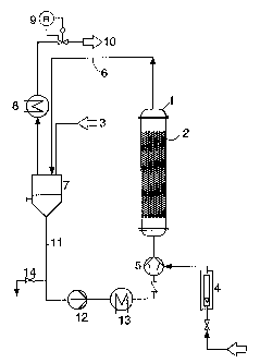
Figure 1: Experimental setup for batchwise reaction process using a
is bubble column reactor modified according to the invention
Figure 2: Experimental setup for continuous reaction process using a
bubble column reactor modified according to the invention
Figure 3: Experimental setup for continuous reaction process using a
tube-bundle reactor modified according to the invention.
zo
Figure 1 shows, by way of example, an experimental setup using a
batchwise bubble column reactor 1 in which a mesh packing 2 whose
geometry is comparable with the Sulzer BX distillation packing is arranged
according to the invention. To carry out the reaction, a liquid reactant
is containing suspended catalyst is first introduced via the filling line 3. A
gaseous reactant is fed in via the connecting line 4 and is mixed in a
mixing nozzle 5 with the circulated suspension, and this mixture is fed to
-g- 220101 ~"
the lower end of the reactor 1. The suspension is discharged from the
reactor together with gas via 6 passed into separating
the line and the vessel
7. From there, the gas is passeda ste gas coolerand via a
via wa 8
pressure-maintaining means 9 wastegas line
into the 10. The
suspension
s passes from the separating line 11 intopump 12, the
vessel 7 via the the
heat exchanger 13, the mixing 5 further intoreactor 1.
nozzle and the
After the end of the reaction,
the suspension is discharged
via the discharge
line 14.
Figure 2 shows a continuous reactor 1 having packings 2 which is
io additionally operated, via the lines 15 and 16, with recycled gas which,
together with fresh gas 4, is mixed by means of the mixing nozzle 5 into
the circulated suspension 11. The reactor discharge is fed via the line 6
into the separating vessel 7 in which the gas phase is separated off and
removed via the line 15. To limit the increase in the level of gaseous
is impurities, a bleed-stream of this amount of gas is removed via the line
10,
and the remaining amount of gas is recycled to the reactor via the line 16.
Only liquid reactant is introduced via the line 3. The suspended catalyst
remains in the reactor system by virtue of the fact that it is retained by
means of a crossflow filter 17 and only catalyst-free liquid 14 emerges and
2o is removed.
Figure 3 shows the embodiment which is preferably to be used in the
case of fast reactions with high heat of reaction and in which the reactor 1
has the design of a tube-bundle heat exchanger and possesses tube bundles
18 in which wire mesh packings 2 are arranged. The heat exchanger 8
Zs present in Figures 1 and 2 may be dispensed with in this embodiment. It
may be retained to perform the function of a heater at the beginning of the
reaction if the reactor is to be fed only with coolant. The functions of the
~~U1~~;;
,, _9_
parts 4, 5, 6, 7, 10, 12, 14, 16 and 17 correspond to those in Figure 2.
EXAMPLES
The advantages of the invention described are illustrated below with
reference to Examples of the hydrogenation of hydrodehydrolinalool to
s hydrolinalool and further to tetrahydrolinalool. The triple bond is
hydrogenated first to a double bond and finally to a single bond.
The reaction was carried out on the one hand in a conventional stirred
container having a three-blade gassing stirrer (1 1 volume, 54 mm stirrer
diameter, 1000 rpm) and flow spoilers.
io On the other hand, a bubble column (400 mm height, 40 mm diameter)
equipped with a mesh packing was used according to the present invention
for the hydrogenation. The experimental setup corresponded to Figure 1.
The geometry of the packing corresponded to a commercial mesh packing of
the type Sulzer BX but the wire mesh had a wire thickness of 0.112 mm
is and was therefore finer and the gaps were narrower. The bend width was
1 mm and the angle of inclination of the bends relative to the vertical was
60°. The surface area of the packing per unit volume was 2200 m2/m3,
these data being based only on the geometric surface area of the mesh
analogously to flat sheets. The liquid containing the suspended catalyst and
Zo the gas was introduced from below into the reactor containing the packing
at
an empty tube velocity of 175 m3/m2h.
In both cases, the reaction was carried out batchwise under 1.1 bar.
The catalyst used was a Zn0-doped palladium catalyst on a CaC03 carrier
which had a mean particle size of about 0.01 mm. The amount of hydro-
Zs dehydrolinalool used was 650 g in the Comparative Experiments in the
stirred container and 840 g in the experiments using the novel reactor. The
hydrogenation was carried out at 80°C.
-1~- 2201~~L
EXAMPLE 1
Packed bubble column containing 0.15 % by weight of catalyst. The
hydrogenation of the triple bond was complete after 1.75 hours and that of
the double bond after 4 hours.
s
EXAMPLE 2
Packed bubble column containing 0.31 % by weight of catalyst. The
hydrogenation times were about the same as those in Example 1.
to COMPARATIVE EXAMPLE 1
Stirred container containing 0.15 % by weight of catalyst. The
hydrogenation of the triple bond was complete after 5 hours and that of the
double bond after 11 hours.
is COMPARATIVE EXAMPLE 2
Stirred container containing 0.31 % by weight of catalyst. The
corresponding hydrogenation times were 3.5 and 7 hours.
COMPARATIVE EXAMPLE 3
Zo Stirred container containing 0.77 % by weight of catalyst. The
hydrogenation times decreased to 3 and 5.5 hours.
The Comparative Experiments show that, in a conventional reactor, the
space-time yield increases with the amount of catalyst introduced. This
means that the reaction rate is controlled by the mass transfer. On the
Zs other hand, when the novel process is used, the reaction times remain
unchanged if the amount of catalyst added is increased. This shows that the
reaction rate is no longer controlled by the mass transfer. The maximum
220~~y.
possible reaction rate is determined in the novel experiments by the mass
transfer from the gas phase to the liquid. It is reached even at relatively
low catalyst concentrations.