Sélection de la langue

Search

Sommaire du brevet 2202954 

Énoncé de désistement de responsabilité concernant l'information provenant de tiers

Une partie des informations de ce site Web a été fournie par des sources externes. Le gouvernement du Canada n'assume aucune responsabilité concernant la précision, l'actualité ou la fiabilité des informations fournies par les sources externes. Les utilisateurs qui désirent employer cette information devraient consulter directement la source des informations. Le contenu fourni par les sources externes n'est pas assujetti aux exigences sur les langues officielles, la protection des renseignements personnels et l'accessibilité.

Disponibilité de l'Abrégé et des Revendications

L'apparition de différences dans le texte et l'image des Revendications et de l'Abrégé dépend du moment auquel le document est publié. Les textes des Revendications et de l'Abrégé sont affichés :

  • lorsque la demande peut être examinée par le public;
  • lorsque le brevet est émis (délivrance).
(12) Brevet: (11) CA 2202954
(54) Titre français: SYSTEME DE VENTILATION A FAIBLE TENEUR EN HUMIDITE POUR FOUR DE ROTISSAGE MUNI D'UNE PORTE FERMEE
(54) Titre anglais: LOW MOISTURE/CLOSED DOOR BROIL OVEN VENTILATION SYSTEM
Statut: Périmé et au-delà du délai pour l’annulation
Données bibliographiques
(51) Classification internationale des brevets (CIB):
  • F24C 15/20 (2006.01)
(72) Inventeurs :
  • VALLE, MIGUEL A. (Etats-Unis d'Amérique)
  • JENKINS, BOBBY JOE (Etats-Unis d'Amérique)
  • MIKALAUSKAS, GEORGE A. (Etats-Unis d'Amérique)
  • PAUL, GREGORY J. (Etats-Unis d'Amérique)
(73) Titulaires :
  • WHIRLPOOL CORPORATION
(71) Demandeurs :
  • WHIRLPOOL CORPORATION (Etats-Unis d'Amérique)
(74) Agent: KIRBY EADES GALE BAKER
(74) Co-agent:
(45) Délivré: 2008-04-01
(22) Date de dépôt: 1997-04-17
(41) Mise à la disponibilité du public: 1997-11-10
Requête d'examen: 2002-02-18
Licence disponible: S.O.
Cédé au domaine public: S.O.
(25) Langue des documents déposés: Anglais

Traité de coopération en matière de brevets (PCT): Non

(30) Données de priorité de la demande:
Numéro de la demande Pays / territoire Date
60/017,370 (Etats-Unis d'Amérique) 1996-05-10

Abrégés

Abrégé français

La présente concerne un four ayant un système de ventilation capable de produire un air d'évacuation à une température réduite et à faible teneur en humidité. Le four comporte une cavité définie par une cloison comportant un trou traversant et délimitée par une porte ayant une entrée d'air pour accepter l'air entrant et un séparateur situé dans la porte pour diviser l'air entrant en au moins un premier trajet et un second trajet. Le four comporte un conduit d'air entourant la cloison ayant au moins une entrée à l'avant du four sous la porte, au moins une entrée à l'arrière du four et une sortie d'air à l'avant du four au-dessus de la porte. En outre, le four a un système de ventilation pouvant produire un air d'évacuation à faible température à la sortie d'air située à l'avant du four. Le système de ventilation comprend une boîte d'évacuation comportant un couvercle d'évent situé sur celui-ci, ledit couvercle d'évent ayant au moins une ouverture; un tube d'évent construit et agencé dans le trou traversant de la cloison reliant la cavité du four à la boîte d'évacuation pour permettre à l'air du four provenant de la cavité de passer à la boîte d'évacuation; et un dispositif destiné à produire une alimentation d'air forcé à partir de l'air aspiré à travers les entrées d'air via le conduit d'air. Le dispositif destiné à produire une alimentation d'air forcé est construit et agencé de telle sorte que l'alimentation en air forcé traverse l'ouverture du couvercle de l'évent, créant ainsi une succion pour combiner l'air forcé à l'air du four à partir du tube d'évent afin de former un flux d'air combiné. L'écoulement d'air combiné est expulsé de la sortie d'air à l'avant du four au-dessus de la porte.


Abrégé anglais

An oven having a ventilation system capable of providing reduced temperature, low moisture exhaust air is provided. The oven has an oven cavity defined by a partition having a through hole and enclosed by an oven door having an air inlet to accept incoming air and a separator located within the door to divide the incoming air into at least a first path and a second path. The oven has an air duct surrounding the partition having at least one inlet at the front of the oven below the door, at least one inlet at the back of the oven and an air outlet at the front of the oven above the door. Also, the oven has a ventilation system capable of providing reduced temperature exhaust air out the air outlet located at the front of the oven. The ventilation system includes a vent box having a vent cap located thereon, the vent cap having at least one opening; a vent tube constructed and arranged in the through hole of the partition connecting the oven cavity to the vent box to allow oven air from the oven cavity to pass to the vent box; and a device for generating a supply of forced air from air drawn in through the air inlets via the air duct. The device for generating a supply of forced air is constructed and arranged such that the supply of forced air travels through the opening of the vent cap thereby creating suction to combine the forced air with the oven air from the vent tube to form a combined airflow. The combined airflow is exhausted out the air outlet at the front of the oven above the door.

Revendications

Note : Les revendications sont présentées dans la langue officielle dans laquelle elles ont été soumises.


CLAIMS
1. An oven having a front and a back, the oven comprising:
an oven cavity defined by a partition having a through hole and enclosed by an
oven
door having a bottom and a top, the bottom of the door having a door air inlet
to accept
incoming air, the door further including a separator located within the door
to divide the
incoming air passing through the air inlet into at least a first path and a
second path, the
second path being disposed between the first path and the oven cavity, air
flowing through
the first path cooling an exterior surface of the door, the first path
extending from the air inlet
to a door air outlet disposed at the top of the door;
the second path extending from the door air inlet, through the door to a top
oven inlet
disposed above the oven cavity;
a first air duct surrounding the partition having at least one bottom inlet at
the front of
the oven below the door, at least one rear inlet at the back of the oven and
an air outlet at the
front of the oven above the door;
a second air duct connecting the top oven inlet to the first air duct; and
a ventilation system including:
a vent box disposed in the first air duct and having a vent cap located
thereon,
the vent cap having at least one opening disposed opposite to and in a spaced
relationship with a fan;
a vent tube constructed and arranged in the through hole of the partition
connecting the oven cavity to the vent box to allow oven air from the oven
cavity to
pass to the vent box; and

the fan disposed in the first air duct, the fan for generating a supply of
forced
air from air drawn in through the top, bottom and rear inlets via the air
duct, the fans
for generating a supply of forced air constructed and arranged such that a
portion of
the supply of forced air travels through the opening of the vent cap and over
the vent
tube to create suction so that the oven air is drawn by the suction through
the vent
tube and combines with the forced air thereby forming a combined airflow, the
combined airflow exhausting out the air inlet at the front of the oven above
the door.
2. The oven of claim 1, wherein the vent tube further comprises:
a catalyst to clean the oven air prior to exhausting same.
3. The oven of claim 1, wherein the vent tube further comprises:
a straight tube portion with a top edge portion at a 45° angle relative
to the straight
tube portion.
4. The oven of claim 1, wherein the air outlet at the front of the oven above
the door
extends across the width of the oven.
5. The oven of claim 1, further comprising:
an oven scoop having a first end adjacent the fan, the oven scoop having
sidewalls
extending to a second end at the front of the oven.
11

6. The oven of claim 1, wherein the at least one opening in the vent cap
comprises:
a louver arranged perpendicular to a flow direction of the supply of forced
air to direct
a portion of the supply of forced air into the vent box.
7. The oven of claim 1, wherein the vent tube is arranged in the through hole
of the
partition connecting the oven cavity to the vent box such that the supply of
forced air travels
over the vent tube to create suction thereby drawing oven air from the oven
cavity into the
vent box.
8. The oven of claim 1, further comprising:
a detector for sensing fan stoppage by detecting an increase in temperature,
the
detector turning off the oven in the case of fan stoppage, the detector being
located in the first
air duct between the fan and the vent box.
9. An oven ventilation system comprising:
an oven having a front and a back including at least one air intake located in
each of
the front and the back of the oven and an air exhaust vent at the front of the
oven;
a fan for generating an airflow;
a vent box having a vent cap located thereon for extracting air from an oven
cavity,
the vent box operatively connected to the fan, the vent cap having an outlet
aperture and at
least one opening positioned for receiving airflow from the fan, a vent tube
connecting the
oven cavity to the vent box to allow oven air from the oven cavity to pass to
the vent box, and
wherein the fan is constructed and arranged such that the airflow travels
through the opening
of the vent cap and over the vent tube thereby creating suction to draw air
from the oven
12

cavity through the vent tube into the vent box to combine with the airflow
therein to form a
combined airflow, the combined airflow exhausting out the air exhaust vent at
the front of the
oven; and
the vent box and the fan combining the air from the oven cavity with the
airflow to
produce a combined airflow having a temperature and moisture content less than
a
temperature of the air from the oven cavity to exhaust said combined airflow
from the air
exhaust vent at the front of the oven.
10. The oven ventilation system of claim 9, wherein the vent tube further
comprises a
catalyst arranged to clean the air from the oven cavity prior to exhausting
same.
11. The oven ventilation system of claim 9, further comprising:
a detector for sensing fan stoppage, the detector for turning off the oven by
detecting
an increase in temperature, the detector being located between the fan and the
vent box.
12. The oven ventilation system of claim 9, wherein the vent means further
comprises:
a vent tube having a straight tube portion with top edge portion at a
45° angle relative
to the straight tube portion.
13. The oven ventilation system of claim 9, wherein the means for combining
the air from
the oven cavity with the airflow further comprises:
a vent box having an outlet aperture; and
a vent cap having at least one opening mounted on the vent box, wherein the
means
for generating an airflow connects to the vent box such that the airflow
enters the at least one
13

opening in the vent cap and the vent means for extracting air from the oven
cavity connects to
the outlet aperture of the vent box.
14. The oven ventilation system of claim 9, further comprising:
an air duct circumscribing the oven cavity, the air duct connected to the at
least one
intake in the front and in the back of the oven and the air exhaust vent at
the front of the oven.
15. The oven ventilation system of claim 14, wherein the air exhaust vent is
located at the
front of the oven above the oven cavity.
16. The oven ventilation system of claim 14, wherein the air exhaust vent is
approximately equal to the width of the oven cavity.
14

Description

Note : Les descriptions sont présentées dans la langue officielle dans laquelle elles ont été soumises.


CA 02202954 1997-04-17
PA-7550-O-RN-USA-RR
SPECIFICATION
TITLE
"LOW MOISTURE/CLOSED DOOR BROIL OVEN VENTILATION SYSTEM"
BACKGROUND OF THE INVENTION
The present invention relates generally to an oven and more particularly to a
low
moisture/closed door broil oven ventilation system.
Known oven designs include single ovens, double ovens and combination ovens
that
have a conventional oven and a microwave oven. Of course, the ovens may be
used for
roasting certain items including turkeys, chickens or other high moisture
foods. The hot,
moist air generated during the roasting of such foods must be dissipated by
some sort of
ventilation system. Ventilation systems are provided in most ovens for venting
some hot
air from the oven and to remove moisture when cooking such a high moisture
load.
However, it is unacceptable to have a large amount of the moisture vented out
of the oven
because of condensation that could occur on the front of the oven or on the
cabinetry
surrounding the oven.
In addition, most ovens have a broiler. The broilers are typically used for
cooking
such items as steaks and other meats at high temperatures. However, when
cooking a steak
or the like in the broiler, a large amount of smoke can develop because of the
fat in the
steak and the high temperatures at which the meat is being cooked. It is
obviously
undesirable for the ventilation or exhaust system of the oven to pump smoke
out of the
oven and into the kitchen. Thus, a ventilation system for an oven needs to
meet certain
design and performance requirements such as those that follow.

CA 02202954 1997-04-17
PA-7550-O-RN-USA-RR
There are two key items involved in the evacuation of air from an oven. The
first
is the volumetric exit velocity of the air from the oven cavity. If the air is
evacuated too
~
quickly from the oven cavity, this can negatively affect the cooking
performance and the
oven preheat time. If the evacuation of the air is too slow, then after the
completion of a
closed door broil, when the user opens the door of the oven, a large
unacceptable smoke
cloud could pour forth from the oven and enter the kitchen. Thus, a
ventilation system
must be designed to handle the dissipation of the smoke cloud to prevent the
kitchen from
being polluted with smoky air.
The second key item in the design of an oven ventilation system is the exhaust
air
temperature. If the temperature of the exhaust air is too hot then there is a
potential of
burning the user or damaging kitchen cabinets that surround the oven. Also, an
exhaust
temperature that is too high may have a negative impact on the efficiency of
the oven. For
example, this condition would draw off too much heat that should be used for
cooking.
Also, if the exhaust air temperature is too low, then there is a condensation
of the cooking
by-products and steam as the exhaust exits the oven. This situation can cause
damage to
surrounding cabinets and possibly violate certain Underwriter's Laboratory or
other safety
requirements.
Several attempts have been made to combat the problems of oven ventilation
systems and provide better ventilation for an oven. For example, U.S. Patent
No.
4,601,279 discloses an oven with a venting system for cooling oven controls.
In Figure 4,
a vertical opening 31 exhausts air from the oven cavity into a passage
exhausting cooling
air. In addition, a catalytic cartridge 32 is provided. The vent system
discharges through
2

CA 02202954 1997-04-17
PA-7550-O-RN-USA-RR
vents across the entire front of the oven after cooling air has mixed with hot
air from the
oven. Thus, this configuration provides a low moisture, low speed air exhaust
from the
oven.
Also, U.S. Patent No. 4,654,508 discloses an electronic oven having an oven
vent
and catalyst reactor 11 exhausting into a cooling duct 10 so that air is mixed
prior to exiting
the oven cabinet. Also, a deflector and a baffle 18 are arranged in the air
flow to help pull
and mix air from the oven cavity.
Further, U.S. Patent No. 4,331,124 discloses a built-in oven having an oven
vent
tube 48 exhausting air into a cooling air chamber 54 to be mixed therein prior
to exhausting
from the oven cabinet.
Thus, a need has arisen for a ventilation system that is cost effective,
easily
manufactured and provides the proper balance of exhaust temperature with the
proper exit
air velocity to achieve low moisture exhaust and optimum closed door broiling
performance
from an oven.
SUMMARY OF THE INVENTION
It is an object, therefore, to provide a low moisture/closed door broil oven
ventilation system that properly balances the exhaust temperature with an exit
air velocity
to achieve low moisture exhaust and optimum closed door broiling performance
in a cost
effective manner.
To this end, in an embodiment, the present invention provides an oven having
an
oven cavity defined by a partition having a through hole. The oven cavity is
enclosed by
an oven door having an air inlet to accept incoming air. Within the door is a
separator for
3

CA 02202954 1997-04-17
PA-7550-O-RN-USA-RR
dividing the incoming air into at least a first path and a second path. An air
duct surrounds
the partition and has at least one inlet at the front of the oven below the
door, at least one
inlet at the back of the oven and an air outlet at the front of the oven above
the door. The
oven also has a ventilation system capable of mixing forced air with oven air
and
exhausting the combined air out the air outlet located at the front of the
oven. The
ventilation system includes: a vent box having a vent cap located thereon, the
vent cap
having at least one opening, a vent tube constructed and arranged in the
through hole of the
partition connecting the oven cavity to the vent box to allow oven air from
the oven cavity
to pass to the vent box; and means for generating a supply of forced air from
air drawn in
through the air inlets via the air duct. The means for generating a supply of
forced air is
constructed and arranged such that the supply of forced air travels through
the opening of
the vent cap and over the vent tube thereby creating suction to draw the oven
air from the
oven cavity. The forced air combines with the oven air to form a combined
airflow. The
combined airflow is exhausted out the air outlet at the front of the oven
above the door.
An advantage of the present invention is to provide an oven ventilation system
that
provides low moisture exhaust air from an oven when cooking high moisture
foods therein.
Another advantage of the present invention is to provide a ventilation system
for a
closed door broil for an oven that reduces or eliminates smoke particles in
the exhaust air
by directing oven air through a catalyst.
A further advantage of the present invention is to provide an oven ventilation
system having a high velocity air supply from a blower capable of drawing hot,
moist air
4

CA 02202954 1997-04-17
PA-7550-O-RN-USA-RR
from the oven cavity and combining the cooler, dryer blower air therewith to
produce a
reduced temperature and reduced moisture exhaust air stream.
Yet another advantage of the present invention to provide a sensor to
recognize a
stoppage of airflow to thereby to turn the oven off for safe operation of the
oven.
BRIEF DES RIPTION OF THE DRAWINGS
Fig. 1 illustrates a double oven in which the low. moisture/closed door broil
oven
ventilation system of the present invention may be utilized.
Fig. 2 illustrates a cut-away side view of an oven incorporating the low
moisture/closed door broil oven ventilation system of the present invention.
Fig. 3 illustrates a cross sectional side view of an embodiment of a vent tube
utilized in the low moisture/closed door broil oven ventilation system of the
present
invention.
Fig. 4 illustrates a plan view of an oven incorporating the low
moisture/closed door
broil oven ventilation system of the present invention.
DETAILED DESCRIPTION OF THE PREFERRED EMBODIMENTS
Fig. 1 illustrates a double oven arrangement 10 having an upper oven 12 and a
lower oven 14. The double oven 10 is mounted within cabinets 15. Each oven 12,
14 has
an oven cavity 16 in which items to be cooked or baked are inserted. The upper
oven 12
also has an oven door 18 shown in an open position in Fig. 1. The oven door 18
has a
handle 20 and a plurality of slot vents 22 located at the top of the oven door
18 near the
handle 20. The upper oven 12 also includes a control panel 24 for operating
the upper
oven 12 and the lower oven 14. Between the control panel 24 and the upper oven
12 is a
5

CA 02202954 1997-04-17
PA-7550-O-RN-USA-RR
row of vents 26. An embodiment of a low moisture/closed door broil oven
ventilation
system 30 is illustrated in dashed lines operatively arranged above both the
upper oven 12
and above the lower oven 14. The ventilation system 30 includes a vent box 32,
a vent box
lid 34 and a vent tube 36. In addition, a motor 38 is provided which supplies
power to a
fan 40 that is used in the ventilation system 30. A discussion of the
ventilation system 30
is found below with reference to Figs. 2, 3 and 4.
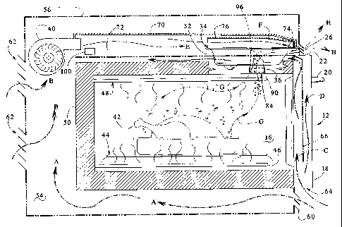
Fig. 2 illustrates a cross-sectional side view of an oven utilizing the
ventilation
system 30 of the present invention. A turkey 42 is shown roasting in the oven
cavity 16 of
the oven 12. The turkey 42 rests on an oven rack 44 above a heating element
46. Also, a
broiler element 48 is provided for broiling steaks and other meats. A heat-
insulating
partition 50 surrounds the oven cavity 16. An airflow pathway 54 is defined by
the
partition 50 and an oven enclosure 56 that encircles the partition 50 and the
oven cavity 16.
Front lower louvers 60 are located below the oven door 18 at the front of the
oven 12.
Thus, air can enter the front lower louvers 60 and travel through the airflow
pathway 54
below the oven cavity 16 and up the back of the oven 12. This supply of air
can be used
for the fan 40. In addition, rear louvers 62 are provided at the back of the
oven enclosure
56. Airflow indicated by arrows A is the air entering through the front lower
louvers 60
and airflow indicated by arrows B is airflow from the rear louvers 62. Both
the A and B
airflows are provided to the fan 40.
In addition, the oven door 18 has an opening or a series of openings 64 at the
bottom thereof for allowing air to enter the door 18. A door partition 66
splits the
incoming air so that the inner air goes through the oven door 18 near the oven
cavity 16.
6

CA 02202954 1997-04-17
PA-7550-O-RN-USA-RR
This air is represented by arrow C. A portion of the airflow represented by
arrow D
travels on the front side of the partition 66 and exits the door 18 through a
plurality of slots
22 at the top of the oven door 18. Such a directing of the airflow helps to
keep the exterior
of the oven door 18 cooler. The portion of the airflow represented by arrows C
travels
around the partition 50, above the oven cavity 16 and back to the fan 40. The
fan 40 then
generates a controlled, forced airflow represented by arrow E. Airflow E is
directed into
an oven scoop 70 which is above an oven partition 72. A portion of the airflow
E travels
over the vent lid 34. This portion of airflow is represented by arrow F. In an
embodiment, a single louver 74 is provided on the vent lid 34 to direct the
airflow into the
vent box 32. The louver 74 is arranged perpendicular to the direction of the
airflow F (see
Figure 4). Thus, the fan air indicated by arrow E enters the vent box 32 via
the louver 74
in the vent lid 34. A vent cap 76 is also provided to direct airflow. The vent
cap 76 is
described further below with reference to Figure 4.
In addition, the vent tube 36 provides a conduit for moist air from the oven
cavity
16 to pass into the vent box 32 as indicated by arrows G. The higher velocity
air supplied
by the fan 40 is indicated by arrow F. This supply of air combines with the
oven exhaust
air indicated by arrow G in the vent box 32. The high velocity air indicated
by arrow F
has a lower pressure than the low velocity exhaust air G coming from the oven
cavity 16.
This pressure differential causes the proper level of evacuation of the oven
cavity 16. The
combined airflow H thus has a relatively low temperature, moisture content and
velocity
than the oven cavity air indicated by the individual component airflow of
arrow G. The
7

CA 02202954 1997-04-17
PA-7550-O-RN-US A-RR
vent tube 36 extends from the oven cavity 16 into the vent box 32. The airflow
H
subsequently travels out the row of vents 26 on the front of the oven 12.
The vent tube 36 is shown in cross-sectional detail in Fig. 3. As illustrated,
the
vent tube 36 has an inlet portion 84 with a flange 86 that is secured to the
inside of the
oven cavity 18. A seal 88 is provided to secure a catalyst 90 within the vent
tube 36. The
catalyst 90 is provided to facilitate a chemical reaction therein to minimize
smoke particles.
The catalyst 90 operates similarly to that of a catalytic converter of an
automobile by using
heat to operate. A tube portion 92 of the vent tube 36 extends above the
catalyst 90 and
has a 45 angled top edge 94. Thus, a slot portion 96 is provided. The forced
air from the
fan 40 passes over the slot portion 96 at the top of the vent tube 36 to draw
the oven air up
through the vent tube 36.
In this manner, the high velocity air supplied by the blower fan 40 through
the vent
channel helps pull the hot, moist air from the oven cavity 16, and the air
from the fan 40 is
exhausted through the vents 26 below the control panel 24 on the front of the
oven 12. In
addition, a sensor 100 is provided to turn off the oven in the event of a loss
of airflow.
The sensor 100 senses if the fan 40 is blowing air. If a lack of air movement
is sensed,
indicating the fan 40 has ceased operation, the oven 12 is shut off. For
example, the
sensor 100 may be a therm-o-disc (TOD) that senses temperature. When the
sensor 100
senses a temperature above a pre-selected value, power is interrupted to the
heating element
46 or the broiler element 48.
Figure 4 illustrates a plan view of the oven 12 incorporating the low
moisture/closed door broiler oven ventilation system of the present invention.
As shown,
8

CA 02202954 1997-04-17
PA-7550-O-RN-USA-RR
the oven scoop 70 has approximately the width of the fan 40 near the fan and
broadens out
to have the approximate width of the oven 12 at the front thereof. The oven
scoop 70 is
thus in communication with the row of vents 26 at the front of the oven 12.
The forced air
generated by the fan 40 is exhausted out the entire width of the row of vents
26. Also, the
combined air from within the vent box 32 is exhausted out the row of vents 26
as shown in
Figure 2.
Figure 4 also shows the approximate arrangement of the vent box 32 and vent
tube
36 with respect to the rest of the oven 12. The louver 74 described above is
located near
an opening 102 that is formed for allowing air to enter the vent box 32. The
louver 74 acts
to deflect the air from the fan 40 down into the opening 102. The deflected
air from the
fan 40 combines therein with the oven air. Also schematically illustrated is
the latching
mechanism 104 for the oven door. The vent cap 76 fits over the vent box 32 and
helps to
direct the forced air from the fan 40 into the louver 74 and opening 102.
It should be understood that we wish to embody within the scope of the patent
warranted hereon, all such modifications as reasonably and properly fall
within the scope of
our contribution to the art.
9

Dessin représentatif
Une figure unique qui représente un dessin illustrant l'invention.
États administratifs

2024-08-01 : Dans le cadre de la transition vers les Brevets de nouvelle génération (BNG), la base de données sur les brevets canadiens (BDBC) contient désormais un Historique d'événement plus détaillé, qui reproduit le Journal des événements de notre nouvelle solution interne.

Veuillez noter que les événements débutant par « Inactive : » se réfèrent à des événements qui ne sont plus utilisés dans notre nouvelle solution interne.

Pour une meilleure compréhension de l'état de la demande ou brevet qui figure sur cette page, la rubrique Mise en garde , et les descriptions de Brevet , Historique d'événement , Taxes périodiques et Historique des paiements devraient être consultées.

Historique d'événement

Description Date
Le délai pour l'annulation est expiré 2014-04-17
Lettre envoyée 2013-04-17
Accordé par délivrance 2008-04-01
Inactive : Page couverture publiée 2008-03-31
Inactive : Taxe finale reçue 2008-01-07
Préoctroi 2008-01-07
Un avis d'acceptation est envoyé 2007-07-20
Lettre envoyée 2007-07-20
Un avis d'acceptation est envoyé 2007-07-20
Inactive : Approuvée aux fins d'acceptation (AFA) 2007-06-13
Modification reçue - modification volontaire 2006-12-13
Inactive : Dem. de l'examinateur par.30(2) Règles 2006-06-21
Lettre envoyée 2002-03-21
Exigences pour une requête d'examen - jugée conforme 2002-02-18
Requête d'examen reçue 2002-02-18
Toutes les exigences pour l'examen - jugée conforme 2002-02-18
Modification reçue - modification volontaire 2002-02-18
Demande publiée (accessible au public) 1997-11-10
Inactive : CIB en 1re position 1997-07-16
Inactive : CIB attribuée 1997-07-16
Lettre envoyée 1997-07-10
Inactive : Certificat de dépôt - Sans RE (Anglais) 1997-07-10

Historique d'abandonnement

Il n'y a pas d'historique d'abandonnement

Taxes périodiques

Le dernier paiement a été reçu le 2007-04-04

Avis : Si le paiement en totalité n'a pas été reçu au plus tard à la date indiquée, une taxe supplémentaire peut être imposée, soit une des taxes suivantes :

  • taxe de rétablissement ;
  • taxe pour paiement en souffrance ; ou
  • taxe additionnelle pour le renversement d'une péremption réputée.

Les taxes sur les brevets sont ajustées au 1er janvier de chaque année. Les montants ci-dessus sont les montants actuels s'ils sont reçus au plus tard le 31 décembre de l'année en cours.
Veuillez vous référer à la page web des taxes sur les brevets de l'OPIC pour voir tous les montants actuels des taxes.

Titulaires au dossier

Les titulaires actuels et antérieures au dossier sont affichés en ordre alphabétique.

Titulaires actuels au dossier
WHIRLPOOL CORPORATION
Titulaires antérieures au dossier
BOBBY JOE JENKINS
GEORGE A. MIKALAUSKAS
GREGORY J. PAUL
MIGUEL A. VALLE
Les propriétaires antérieurs qui ne figurent pas dans la liste des « Propriétaires au dossier » apparaîtront dans d'autres documents au dossier.
Documents

Pour visionner les fichiers sélectionnés, entrer le code reCAPTCHA :


Pour visualiser une image, cliquer sur un lien dans la colonne description du document. Pour télécharger l'image (les images), cliquer l'une ou plusieurs cases à cocher dans la première colonne et ensuite cliquer sur le bouton "Télécharger sélection en format PDF (archive Zip)" ou le bouton "Télécharger sélection (en un fichier PDF fusionné)".

Liste des documents de brevet publiés et non publiés sur la BDBC .

Si vous avez des difficultés à accéder au contenu, veuillez communiquer avec le Centre de services à la clientèle au 1-866-997-1936, ou envoyer un courriel au Centre de service à la clientèle de l'OPIC.


Description du
Document 
Date
(aaaa-mm-jj) 
Nombre de pages   Taille de l'image (Ko) 
Dessin représentatif 1997-11-18 1 26
Description 1997-04-16 9 351
Abrégé 1997-04-16 1 36
Revendications 1997-04-16 7 166
Dessins 1997-04-16 3 127
Revendications 2006-12-12 5 143
Dessin représentatif 2008-02-28 1 28
Courtoisie - Certificat d'enregistrement (document(s) connexe(s)) 1997-07-09 1 118
Certificat de dépôt (anglais) 1997-07-09 1 165
Rappel de taxe de maintien due 1998-12-20 1 110
Rappel - requête d'examen 2001-12-17 1 118
Accusé de réception de la requête d'examen 2002-03-20 1 180
Avis du commissaire - Demande jugée acceptable 2007-07-19 1 164
Avis concernant la taxe de maintien 2013-05-28 1 171
Correspondance 2008-01-06 1 49