Note : Les descriptions sont présentées dans la langue officielle dans laquelle elles ont été soumises.
CA 02202982 1997-04-17
~ n_~rOLllMET~Ic MO'TOR
FIELD OF THE lNV~ ON
~he present invention relates generally to a thermo-
volumetric motor and relates particularly, though no~
exclusively, to a thermo-volumetric motor which is
acti~ated by a phase change sub~tance ha~ing a relatively
high latent heat o~ fusion Typically, the phase change
~ubstance is a hydrate salt which is heated from an
exte~nal heat source, such as ~unlight. The present
~0 invention ~u~ther relates generally to a method ~or
producing motive power..
R~C~OUND T0 ~HE lN~ OI~
Motive power can be produced in a variety of known way~.
For example, turbines in a hydro-electric plant are dri~en
l'S by water and each turbine is operatively connected to a
generator which produces electricit~. The motive power is
produced by the 10w of water within a turbine. A steam
engine produces motive power by boiling water to create
steam which then drives a piston in a reciprocating motion
2~ within a cylinder. The reciprocating motion can then be
adapted to produce ro~ary motion for driving a vehicle, or
alternatively dri~ing a genera~or to produce electricity.
Hydro-electricity has en~ironmental drawback~. For
example, the ~low o~ water from a lake can detrimentally
a~fect the ecosystem in and around the lake. To this
extent the water is a limited resource.
The production of steam from water re~uires heat and
generally combus~ion. Combustion result~ in both
combustion product~, such a~ carbon dioxide, and unbur~t
~uel which are harmful to the en~ironment . T~e trea~ment
o~ tha~e harmful products can be expenSive and proces-des
which scrub an exhau~t gas or promote complete combu~tion
of unburnt fuel are rarely totally ef~icient, This is an
", . . .
. - ~ ., .
. ~; . i . , . ~ . . ..
. .
CA 02202982 lss7-04-l7
inherent problem with most combustion engines.
Another drawback with a large number of engines or motors
is their e~iciency. The energy input relative to the
power output is relatively large due to losses a~sociated
S with ~riction, heat and pressure los~e-~, incomplete
combustion, and other similar factors. Particularly with
geared motors frictional losse~ can substantially detract
from the overall efficiency of the motor. With combu~t~ on
engines pressure losses which generally increase with the
age o~ ~he motor are also a pro~lem and o~ten require
complex and expensive mechanical sealing.
~UW~ARY OF THE ~v~llON
An in~en~ion of the present invention is to provide a
thermo-~olumetric moto~ which can prod~ce motive power both
15 e~i~iciently and enviror~nentally sa~ely.
According ~o a first a~pect of ~he present invention ~h~re
is provided a thermo-volumetric motor comprising:
a continuous ~luid path adapted to carry a
substantially..compres~ible fluid, said continuous fluid
20 path having heat transfer mean6 arld flow converting means
in f luid CO~unUnicatlon with each other, said ~low
converting means being adapted to convert a flow o~ the
compressible fluid in the f~luid path to a motive power and
said heat transfer means cont~;~1 ng a first phaqe change
sub~tance having a relatively high latent heat of fusion
and adapted to absorb heat from an external heat source
whereby, in use, the ~irst phase change substance can
absorb heat from the external heat source thus ~using a
portion of said phase change substance, and thereafter said
portion of the phase chan~e substance can 301idify thus
releasing latent heat which i3 absorbed by the compressible
fluid thereby e~n~i~ and thus effecting a ~low of the
compresslble ~luid through the flow con~er~iny means to
provide motive power.
.... .. ~ .
'. ' :-."" ` ' ~ '
,, ; .
CA 02202982 1997-04-17
::
-- 3
Typically, the co~tinuous fluid path further compri~e.
cooling mean~ in ~luid communication with the heat transfer
mea~ and the flow converting means so that the
compre~sible fluid can ~e cooled by the cooli~g means
5 be~ore said compressible ~luid is heated by the heat ,;
transfer meanC.
':
Pre~erably, the continuoll~; f luid path further comprises a
pump operatively coupled to the i~low convertin~ mean~ and
in fluid co~ml~nication with the heat transfer means, the
flow convertin~ means, and the cooling mean~ whereby, in
use, movement of the ~low co~vertin~ means drives the pump
thereby pumping the compressible fluid through the
conkinuou~ fluid path.
~ypically, the c~olin.~ means i~ a first accumulator
containing a second phase change substance havi~g a
relatively high latent heat of ~usion and a relati~ely low
mel~ing-point whereby, in use, heat ~rom the compressible
~luid can be absorbed by the ~econd phase change substance
thus ~using a portion of said phase change subs~ance which
cools the compressi~le fluid pas~ing through the cooling
mean~. -
Txpically, the ~hermo-volumetric motor ~urther comprises a
collector adapted to absorb heat ~rom the external heat
source, the collector being in heat conductive
communication with the heat transfer means so that, in use,
heat absorbed by ~he collector can be transferred to the
first phase change subs~ance contained in the heat trans~er
means wherein a portion of the phase change subs~ance
~uses.
Typically, the flow converting means compri~es:
a chamber adapted to recei~e the compre~sible
fluid and in 1uid co~l]n;cation with the heat trans~er
means; and
; -- . ; 1 . ; _,, ,
b
~: i
.,,, j ,. . .
'~
CA 02202982 l997-04-l7
-
-- 4
a flow skructure mo~ably coupled to the chamber
wherein the flow o~ compressible fluid in the chamber .
forces the ~low structure to move ~o a~ to provide motive
power.
S Pre~erably, the flow structure comp~ises a pair o~ axially
spaced apart rotors connec~ed to a ~haft wherein the ~low
converting means comprises a turbine in ~luid communica~ion
with the heat transfer means. Typically, the pair of
spaced apart r~t~r~ de~ines a subqtantially sealed portion
of the chamber therebetween such that, in u~e, the
compressible fluid is injected into -~aid portion of the
chamber, and said compressible ~luid f~ictionally engages
and thu~ rotates the rotors~
Alternatively, the flow converting means comprises: !
a resilient tube adapted to ca~y the
compressible fluid and in fluid communication with the heat
~ransfer means; and
engaging means con~igured to operatively engage
the ~lexible tube wherein the flow o~ compre~sible fluid
through the~lexible tube moves the engaging means so as to
provide moti~e power.
In one embodiment, ~he engaging means comprises a
rotational ~tructure having at lea~t one roller coupled to
a coaxial sha~ so that, in use, said at least one roller
can enga~e the flexible tube and the $10w o$ compre~sible
fluid throu~h the ~lexible tube causes ~aid at lea~t one
roller to move and rotate the rotational ~tructure which
can then provide motive power.
Pre~erably, -~aid rotational structure ha~ more than one
roller rotationally coupled ~o and disposed about the
coaxi~1 ~ha~t ~o t~at, in use, at least ono o~ said rollers
engages the re~ilient tube at any one time wherein the flow
o~ compressible fluid through the flexible tube ensures
. ., ~ - . ... .
.
,
.
. ~, , .
CA 02202982 1997-04-17
.
"
- 5 - :
rotation of ~he rotational struc~ure at all times.
In an alterna~ive embodiment, the en~aging means comprises
a pair o~ rotational structures connected hy a common .-~
coaxial shaft, each rota~ional structure having at le~st
5 one roller used ~o engage a flexible tube of a pair of ,.
~lexlble tubes, respect:ively, wherein at least one o~ said
rollers engages one of said flexible tubes at any one time.
Typically, the heat tr,~nsfer means comprises;
a ~irst ~ube adapted to carry the ~ompressible
fluid through ~he heat transfer means; and
a shell ~urrounding a portion o~ the ~irst tube,
said shell containing the firs~ phase change substance
which is in contact wi~h the first tube whereby, in use,
latent heat can be transferred fxom the first pha~e chan~
!3ubstance to the compressible ~luid via the ~irs~: tube o~
the heat trans~er means.
Typically, the heat tran~er means further comp~ises a
jacket surrounding the sh~ll and adapted to carry a heat
transfer fluid whereby, in use, heat from the heat trans~er
~luid can be transferred to the ~irst phase change
substance ~hereby meltin~ the first phase change substance
and storing latent heat.
In one example, the jacket is in 1uid co~ml~n;cation with
the collector wherein heat absorbed by the collector can be
trans~erred to the fir~t phase change sub3tance via the
heat tran~er fluid.
In another embodiment the heat transer mea~ ~urther
comprises a second accumulator containin~ a thlrd phase
change substance having a relatively hlgh latent heat o~
3 o ~u~ion, said second accumul~tor in heat c~nduc~ive
communication with the collector and in fluid communication
with the jacket, so tha~, in ~se, the heat transfer fluid
.' ' ' .'.
~ .. . . ~
.
CA 02202982 1997-04-17
,s
- 6 -
can be preheated by the l~tent heat of the third p~ase
change s~bstance be~or.e said heat trans~er ~luid ~lows to
the j acket.
According to a second aspect of the present inven~ion there
is provided a method ~or producing motive power comprisin~
the steps of:
absorbing heat, from an external heat ~ource, on
a ~irst phase change substance contained in heat trans~er
means wherein a portion o~ the first ph~se change substance
fuses, said first phase change substance having a
relatively high latent heat of fusion;
transferring latent heat ~rom said portion o~ the
first phase change substance, upon solidification thereo~,
to a compressible ~lui~d provided in a continuous ~luid path
thereby expanding the compressible ~luid and e~fecting a
~low o~ the compressi~le ~luid in the ~lui~ path; and
converting the ~low o~ compressible fluid through
the ~luid path so as to produce mo~ive power.
Pre~erably, the method further comprises the step of
cooling the compressible fluid and returning said
compre~sible ~luid to the heat transfer means.
Typically, the step o~ cooling the compressible ~luid
involves absorbing heat ~rom the compressible ~luid by
exchanging heat with a second phase change substance,
having a relatively high laten~ heat o~ fusion and a
relatively low melting-point, wherein the compress~ble
~luid is cooled.
Typically, the me~hod further comprises the ~tep of driving
a pump operatively coupled to the flow converting means
whe~ein compres~i~le ~luid is pumped to the heat trans~er
mean.~ u~in~ the pump.
.... ~ .. . . ...... ...... .
. ,' ,' ' , .
.. . .
- . , . _
., :,. . . . .
CA 02202982 l997-04-l7
Pre~erably, the method further comprixe~ the skep of
absorbing heat from the external heat ~ource onto a
collector which is in. heat conduc~ive communication with
the heat transfer means, wherein absorbed heat can be
~rans~erred ~rom the collec~or to ~he ~irst phase change
substance of the heat ~rans~er means.
In one example the me~hod further compri~es the s~ep of
preheating a heat tra~er ~luid circulating ~etween the
heat transfer means and an accumula~or cont~;n;ng a third
phase chan~e substance ha~ing a relatively high latent heat
o~ usion, wherein the preheated heat transfer fluid can
trans~er heat to the ~irst phase change substance o~ ~he
heat trans~er means.
Typically the first, second and/or third phase change
substance~ are first, second and~or third hydrate salts
respectively, each having a high latent heat of fusion.
Pref~rably the fir~t hydrate ~alt and ~he third hydrate
salt each have a melting-point of between OQC to 100C.
Pre~erably the first hydrate salt and ~he third hydrate
salt each have a latent heat of fusion of greater than 50
kilocalories/litre (kcal/l).
In o~e example the ~îr~t hydrate sal~ and the third hydrate
salt compri~es sodiUm ~cetate trih~drate or a derivative
thereof.
Preferably, the ~econd hydrate salt ha~ a meltin~-point o~
less than 0C.
In one example the ~econd hydrate salt comprise~ o~ a
stoichiometric mixture o~ sodium chloride, calcium
chloride, and demineralised w~ter or a derivati~e thereo~.
., .,, ,, ~, .
~, , . - .
. ' '!, ; - . `
'.' "~' .' .~ '; . ' .. i .
CA 02202982 lsg7-04-l7
;
Typically, the compressible ~luid compri~e~ a refrigerant
such as methane, chloro-difluoro or a derivative thereof.
Typically, the collec~or is a solar collector adapted to
absorb sunlight.
Preferably, the refrigerant does not contain a halogen
element.
BRIEF D~SCR~PTION OF T~ DRAWING8
In order to achieve a better understanding of the nature o~ ,
the present invention a pre~erred embodime~t of a thermo- i
volumetric motor according ~o the present invention will
now be described in some detail, by way of example only,
with reference to the accompanying drawi~gs in which:
Figure 1 is a schema~ic of an embodiment of a
~hermo-volumetric motor
15Figure 2 is a cross-sectional view taken axially
t~rough one embodiment of ~low converting mean~;
Figure 3 i~ a detailed plan ~iew o~ an
al~ernative embodiment of flow converting means; and
Figure 4 is a detailed perspective ~iew of some
of the components of the ~low con~er~ing means shown in
Figure 3.
DETATr~n n~g~TPTION OF ~-~KK~D EMBODI~NTS
As shown in Figure 1, this embodiment o~ a thermo-
volumetriC motor 10 comprise~ a continuous ~luid path i~l
the ~orm of a re~rigerant path 1~, and a solar collector
14. The refri~erant path 12 i~ adapted ~ carry a
refrigerant fluid in this example methane, chloro-di~l~ouro
or a deriva~ive thereGf. However, it i~ preferable ~or
environmental reasons th~t the refrigeran~ is not a
halogenated hydrocarbon.
The con~inuous re~rigerant path 12 includes heat trans~er
means, in this example a first heat exchanger 16, ~low
: '' ` ` . . .: -
,
." ' . '' ' ' ' , .
CA 02202982 l997-04-l7
,
-
_ g _ '
conver~ing means shown ~enerally as 18, a pump 19, and
cooling means, in this example a ~irs~ accumulator or
condenser 20 In a downstream direction the re~rigerant
can f~low through the i~low converting meani~ 18, the
conden~er ~0, the pump 19 and the first hea~ exchan~er 16.
A throttle valve 21 is located upstrea~ o~ the flow
convertin~ means 18 to control flow thereto.
The ~ir~t heat exchan.ger 16 comprises a shell and tube
arrange~ent (not shown) w~erein the re~rigerant is passed
through a ~irst tu~e ~ormed in the shape of a triple-helix.
The shell contains a ~irst phase change -~ubstance, in this
example a first hydrate salt sodi~m acetate trihydrate,
having a relatively high latent heat of fusion and a
melting-poin~ o~ approximately 58c. The first heat
ex~i~er 16 is housed in a sealed ; acket 22 surrounding
the shell and adapted to carry a heat trans~er fluid, in
~his example water. The jacket 22 has an inlet 24 for
receiving water, and an outlet 26 for discharging water.
The ~irst heat exchanger 16 further includes a second
accumulator 28 containing a third phase change substance.
In thi~ example the third phase cha~ge ~u~stance is a third
hydrate salt, sodium acetake trihydrate. The third hydrate
salt i~ con~ained within a vessel 30, the vessel 30 boing
coupled to the jacket 22 o~ the first heat exchAn~er 16 via
25 a ~irst recirculation tube 32 adapted to circulate the heat
transfer 1uid, in this example water. The vessel 30 is
similarly coupled to the ~olar collector 14 via ~ second
recirculation tube 34 adapted to circul~te water.
In thi6 embodiment the solar collector 14 has an upper
surface (not Qhown) expo~ed to sunlight, the upper surface
co~struc~ed of a material having relatively low
re~lec~ivity and radiation. The upper sur~ace i~ coated
with a composite bitumen/la~ex product marke~ed and sold
under a trade mark IMPERSPRAY. The collector 14 has a base
' i ,` ' ~ ' ' ~ ~: .,,
CA 02202982 1997-04-17
- 10 -
layer constructed o~ a high density pol~styrene material
having relatively high thermal insulation. The coating of
IMPERSP~AY covers an upper s~rface of the base layer~ A
corrugated sheet, constructed o~ a polycarbonate material
being substantially transparent to sunlight, rests on the
coa~ing of IMPERSPRAY.. A series of adjacent channels are
thus de~ined between a lower sur~ace o~ the corru~ated
sheet and the coating o~ XMPERSPRAY. It is believed that a
~reenhouse heating e~ect occurs in the ad;acent channels
such that the ef~iciency of ~he collector 14 is increased.
The water circulating through the second recirculation tube
3~ flows through a corrugated tube (not shown) connected at
each end thereo~ ~o the recirculation ~ube 34~ The
corrugated tube is laid in a serpentine arrangement
immediately adjacant the upper sur~ace o~ the solar
collector 1~.
Heat from sunligh~ a~sorbed on the ~olar collector 1~ i~
transferxed to the third hydrate salt contained in the
second accumulator 28 via the water circulating through the
second recirculation tuhe 34. The firs~ hydrate salt
contained in th~ shell i~ ~hen heated ~ia the wate~
circulating between the second accumulator 28 and the
jacket 22 of the fir~t heat exchanger lG.
The condenser 20 can take a variety of ~orms. In this
embodiment the condenser 20 comprises a refrigerant tube
(not s~own) formed in the ~hape o~ a helix, the tube housed
in a shell 36 o~ the condenser 20. The shell 36 contains a
second phase change substance, in thi~ embodiment a second
~ydrate salt being a stoichiometric mixture o~ sodium
chloride, calcium chloride, and demineralised wa~er or a
derivative o such a mixture. The second hydrate salt has
a relatively hi~h latent heat of fusion and a relatively
low melting-point, in this example approximately -21C.
'- . '
CA 02202982 1997-04-17
The pump 19 is operatively coupled to the flow con~erting
means 18 via an endles~ belt (not shown). Alternatively,
the pump 19 can be driven by electricity produced from an
electrical ~enerator operatively coupled to the ~low
converting means 18. Rotation o~ the ~low converting means
18 thus causes ~he p~np 19 to rotate and pump refrigera~it
t~rough the refrigerant path 12. The pump 19, in this
example, is o~ a positi~e displacemen~ tXpe. A~vantageously
refrigerant can only flow in one direction through the
positive displacement pump 19.
The throttle valve 21 is used to control flow of
refrigerant to the flow conver~ing means ~8. The ~al~e 21
is manually con~rolled such that there is an ups~ream
pressure o~ approximately 15 sa~ and a downstream pressure
. 15 o~ ~pproximately 8 Ba~, depe~ largely on the rotational
or linear ~peed reguired of the flow converting means 18.
This pressure differe~itial will also depend on the
compressible fluid used, the ~irst phase change substance
used, and other related factor~. i
The flow converting me~ns 18 can take a variety o~
con~igurations.
In one preferred embodiment, as showni in Figure 2, the flow
conver~ing mean~ comprise~ a sealed turbine shown generally
as 40. The sealed turbine 40 has a coaxial shaft 42
rotationally mounted within a ~ha~t housing 44 via a pair
of bearings 46. At o~ie end the shaft 42 is axially fixed
to a pair o~ rotors 48A, 48B . A nut 50 threFIrl; ngly engages
the end o the shaft 42 and ~ixes the pair o~ rotors 48A,
48B to the sha~t 42 with a spacer 50 located therebetween.
The rotor~3 48a, 48~3 are hou~ed in a turbine ca5ing 54 which
i8 connected to ~he shaft housing 44.
An opposing pair o~ seals 56A, 56B is located within the
turbine casing 54, di~posed about the ~ha~t 42 to pre~ent
i-: ; - . . . , A
.' : ''' ' ~ :..
.
.. , , . . . i
CA 02202982 1997-04-17
i
~he i~gress of re~rigerant into and egress o~ lubricant
~rom the sha~t ho~sin~ 44. A pair o~ 5eal retainers 58A,
58B also locate~ within the turbine ~asing 54 about the
sha~t 42 so as to hold each of the ~eals 56A, 56B in place.
5 A similar seal arrangement is used at the oppo~ite end o~ j
the sha~t 42 to pr~vent the egre~s o~ lubricant from the
sha~t housing 44.
A turbine casing cover 60 connects to the turbine casin~ 54
and seals the pair o~ rotors 48A, 48B withi~ the ca~ing 54.
A housing end plate 62 connects to ~he shaft housing 44 and
re~ains the seal arrangement at the opposite end of the
sha~t 42. A no~zle (not æhown) is co~nected to ~he turbine
casing 5~ and is designed to i~jec~ refrigerant in~o a
substantially sealed chambe~ 61 defined betw~en the rotors
48A, 48B.
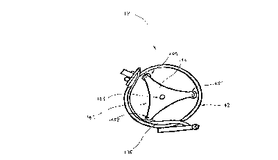
As shown in Figures 3 and 4 an al~ernative embodiment of
the flow converting means 18 comprises a resilie~t tube 138
and engaging means, in thi~ example a rotational structure
or rotor 140. The resilient tube 138 i~ coupled at each
end to a housing 142. T~e housing 142 is s~bstantially
cylindrica~ in shape. The ~ube 138 is adapted to carry the
re~rigerant and i~ in fluid communicatio~ with the first
hea~ exchanger 16.
The rotor 140 comprises a coaxial shaft 144 connected to a
pair of axially ~paced triangular-~haped plate~ 146. A
roller 148 is rotationally coupled between oppo~ing apexes
of the pair of plates 146. Three rollers 148A, 148B, 1~8C
are thus disposed about the pair of plates 146 with an
angle o~ approximately 120 between adjacent rollers 148.
The axis of rotation o~ each roller 148 is substantially
parallel to the axis o~ the coaxial sha~t 144
The rotor 140 is rotationally supported in the hou~ing 142
so that at least one of the rollers 148 contacts and
." ~ ., ! . ' ~';; ' ' ' . . = , -- . . ' . '. . . ;j
., . ' I . , : _ . ' ' ' . . .
CA 02202982 l997-04-l7
- 13 -
resiliently de~orms the resilient tube 138. A flow of
refrigerant through the ~ube 138 forces the r~ller 148 to
mo~e relative to the housing 142 and hence a motive ~orce
is applied to the rotor 140. The coaxial sha~t 144 can be
5 connected to a pulley (not shown), the pulley operatively
coupled to the pump 19 ~ia the endles~ belt. The rotor 140
can be used to provide motive power, ~or exam~le, to drive r
a generator (not shown) and produce electricity~
t
operation of the thermo-volumetric mo~or 10 exemplified
10 above will now be described in detail.
The solar collec~or 14 is exposed to sunlight and the upper
IMPERSPRAY surface absorbs heat from the sunlight. Water
in the corrugated tube, connected to the second
recircu7ation tube 34f is thus heated and heat there~rom
15 transferred to the third hydrate salt ~odium acetate
trihydrate, contained ~ithin the vessel 30 of the second
accumulator 28. When the third h~drate salt fu~e~ latent
heat is stored in the second accumulator 28.
Water recirculating throu~h the ~irst recirculation tube 32
20 cool~ the ~hird hydrate salt a~d, upon solidi$icatio~ of
the hydra~e salt, abscrbs heat in the ~orm of latent heat.
The heated water then exchanges heat with the f irst hydrate
~alt contained in the shell of the ~irst heat exchanger 16.
A portion of the firs~ hydrate salt then fuses and stores
25 latent heat.
The re~rigerant path 12 has been charged with the
refrigerant 1uid, in this example methane, chloro-
dlfluoro. The re~rigera~t in the fir~t tube ~f the heat
exchanger 16 cools the first hydrate salt causing it to
30 solidi~y and the re~rigerant then absorbs the latent heat
o~ the ~ir~t hydrate salt. The refrigerant thereky expands
and a ~low of rerigerant through the refrigerant path 12
is e~fected. The pump 19 upstream o~ ~he heat exchanger 16
. , S . . - . ', ' . !
"" ' ': " ' ' ' ' ' ''. ' `' i
'
CA 02202982 l997-04-l7
-- 14 --
is unidirectional, as ~escri~ed ~bove, and therefore the
refrigerant ~lows from the he~ e~oh~nger 16 to the flow
conYerting means 18.
In the preferred form of the flow converting mean~
illustrated in figure 2 th~ re~rigerant is injected into
the sealed chamber 61 between the rotors 48A, 48B via the
nozzle (not shown). The refrigerant frictionally engages
the rotor~ 48A, 48B and thus effec~s ro~atlon of the rotors
48A, 48B and the coaxial shaft 42.
In the alternative form of the flow converting means
depicted in figure~ 3 and 4 the re~rigeran~ is injected
into the re~ilient tube 138. The flow of re~rigerant
through ~he resilient tube 138 ~orces one of the rollers
148 to move relative to the housing 142. ~he shaft 14~ of
the rotor 140 i9 thus rotated. As best shown in Figu~e 3
t~e rollers 148 and tube 138 are arranged ,~uch that at
least one roller 148 presses against or engages the tube
138 at any o~e time. Hence, ths trAnsfer of motive power
to rotor 140 i9 maintained substantially conti~uously
during rotation o~ ~he rotor 140.
The pump 19 i~ operatively coupled to the shaft 42 or 144
and also rot~tes thereby pumping refrigerant throu~h the
re~rigerant path 12.
The throttle ~al~e 21 is adjusted so tha~ a selected ~low
o~ refrigerant passes through the flow converting means 18.
This will vary depending on the ~actors described above.
Refrigerant then flow~ to the condenser 20 ~hrough an
enlarged diameter tube wherein the refrigerant expands and
cools. The re~rigerant i8 at this stage at a temperature
30 greater ~han the melti~g-point of the second hydrate salt.
Consequently the refrigerant transfers heat to ~he second
hydrate salt fusing the sal~, and there~ore the re~rigerant
., .: , - . ............................... . .
.
... ' :,' ' ' . . .. ; ~;, ' '
CA 02202982 1997-04-17
c~ols and preferably changes phase from a gas to a li~uid.
The li~uid refrigerant is then pump~sd via the pump ~9 to
the ~ir~t heat exchanger 16. The li~uid refrigerant
absorb~ heat from the first hydrate salt and upon
solidi~ication o~ the salt is heated, changing phase back
to a ga, a~d expands. The expanded ~e~rigerant gas
therea~ter ~lows to t he f low converting means 18 via the
throttle valve 21 thus providing motive power.
Now that pre~Serred embodiments o~ the present ~nvention
have been described it will be apparent to per~on~ skilled
i~ the relevant arts that the thermo-volumetric mo~or has
l:he following ad~rantages over the admitted prior art:
(1) the thermo-volumetric mo~or has no
environmentally unsa~e combucStion products;
1~ (2) ~he ~hermo-volumetric motor can be adapted to
utilise heat from sunlight absorbed on a solar collector,
( 3 ) the thermo-volumetric motor uses phase change
subistances to store energy in the form o~ latent heat which
can then be used to provide motive power;
(4) the thermcs-vol~metric motor can be adapted to use
e~ergy such as solar or waste energy which is generally not
a limited reso~rce su.ch as, for example, is th~ case with
mineral ~uels;
l5) the thermo-~olumetric motor is cold running and
there~ore does not require cooling which may detract from
its effi~iency; and,
( 6 ) the ~hermo-vol~netric mo~c~r operates ~i~hout
combustion noise.
It will be apparent to persons skilled in the rele~an~ arts
that numerous variations and modi~ication-~ can be made to
the thermo-~olumetric motor and method ~or pro~idin~ motive
power in addition to tho~e already mentioned without
departing ~rom the basic inventi~e concepts of the presen~
invention. For ex~mple, the flow converting mean~ may
comprise a turbine means which i~ adap~ed to be driven by
CA 02202982 lsg7-04-l7
- 16 -
the compressed ~luid ~herein motive power is provided. The
in~en~ion i~ n~t limi.ted to the phase change substances
herein described but rather may include any phase change
substance which can exchange latent heat with a compressed
5 fluid as described above. Furthermore, the first hea~ -
exchanger need not include a second accumulator as
described. The ~econd accumulator in the ex~mple described
advantageously provides or a large storage bank of latent
heat when, for example, heat cannot be provided to fuse or
charge the pha~e change substance. The heat transfer means
and the condenser de.~cribed herein are not limited to tho~e
3pecific arrangements described. All such variations and
modi~ica~ions are to be considered within the scope o~ the
~resent invention the nature of which is to be determined
~rom the foregoing description.
.
. , . , ~ . . . -
:. ., , , . :
. . . . - . .