Note : Les descriptions sont présentées dans la langue officielle dans laquelle elles ont été soumises.
CA 02203305 2000-02-O1
REGENERATIVE DESICCANT AIR DRYER
FIELD OF THE INVENTION
The present invention generally relates to a system for
drying air supplied by a compressor unit for use in a pneumatic
system. More particularly, the present invention relates to a
regenerative air dryer system that alternately switches between
removing moisture from air to be used by the pneumatic system by
passing it through a first drying assembly while purging
previously collected moisture from a second drying assembly and
removing moisture from air to be used by the pneumatic system by
passing it through the second drying assembly while purging
previously collected moisture from the first drying assembly.
Still more particularly, the present invention pertains to a
desiccant canister assembly housing which features a mechanism
1
CA 02203305 1997-04-22
for aligning and securably retaining a desiccant canister within
the desiccant canister assembly housing of an air dryer system.
BACKGROUND OF THE INVENTION
It is well known that air dryer systems are designed
to remove moisture vapor from a stream of compressed air into
which the air dryer system is incorporated. In practice, an air
dryer system employs one or more standard air drying assemblies
each of which contains a moisture absorbing material to absorb
the moisture from the air. In air dryer systems having one air
drying assembly, the air drying assembly through its moisture
absorbing material absorbs the moisture suspended in the
compressed air passing through it until the compressor stops
operating after a preset time. By design, this type of air dryer
system then automatically flushes a quantity of the dried
compressed air stored in a purge volume back through the moisture
absorbing material to draw out the absorbed moisture . The stream
of compressed air with the revaporized moisture it carries is
then discharged to the atmosphere thereby regenerating the
moisture absorbing material contained in the air drying assembly.
In air dryer systems having two air drying assemblies,
the air drying system alternately cycles between removing
moisture from air passing through a first drying assembly while
purging from a second drying assembly moisture previously
collected therein and removing moisture from air passing through
the second drying assembly while purging from the first drying
assembly moisture previously collected therein.
2
CA 02203305 1997-04-22
Prior to the present invention, such prior art air
dryer systems generally have used the standard air drying
assembly to perform the air drying function. Whether the air
dryer system employs one or more standard air drying assemblies,
each standard air drying assembly inserts into a housing designed
to hold same. The prior art housings, however, generally retain
the standard air drying assembly through a tight press fitting,
or in other terms, interference fitting of the assembly within
the housing. Specifically, the fit of the standard air drying
assembly into its corresponding housing in the air dryer system
is so tight that it typically must be hammered into the housing
with a mallet or like instrument.
The standard air drying assembly and corresponding
housing design thus present a number of shortcomings . First, the
process of installing the standard air drying assembly into the
housing is quite strenuous and takes too much time. Second, one
can not be sure whether the standard air drying assembly is
properly aligned within the housing so that the top of the
assembly seats against and makes an air tight seal with a sealing
face of the housing. Third, removal of the standard air drying
assembly from the housing is often quite difficult because of its
tight fit within the housing. For these reasons, a regenerative
air dryer system inclusive of a novel air drying assembly housing
that does not exhibit the disadvantages outlined above is
described and claimed herein as follows.
3
CA 02203305 1997-04-22
The present regenerative air dryer system can be
applied to a wide variety of pneumatic systems. Typical of the
types of pneumatic systems to which the instant system could be
applied include the pneumatic brake systems of passenger transit
and freight railroad trains, subway trains and various other
types of rail related transportation systems. Further examples
include the pneumatic brake systems of various truck transport
vehicles. Other types of pneumatic systems to which the present
system could be applied may indeed be found outside the
transportation field.
It should be noted that the foregoing background
information is provided to assist the reader in understanding the
instant invention. Accordingly, any terms of art used herein are
not intended to be limited to any particular narrow
interpretation unless specifically stated otherwise in this
document.
SUI~IARY OF THE INVENTION
In a presently preferred embodiment, the present
invention provides an air drying canister housing for a desiccant
canister in an air dryer system. The canister housing includes
a main portion having an upper base and a lower portion having
a lower base. A canister bore is defined between the upper and
lower bases when the main and lower portions are fastened to each
other. The main portion defines a supply port through which a
stream of moisture-bearing air is directed into the housing for
passage through the desiccant canister during a drying mode of
4
CA 02203305 1997-04-22
operation. The main portion also defines a delivery port through
which a stream of dried air is directed from the housing during
the drying mode. The lower portion defines a purge port through
the lower base through which a stream of remoisturized air is
expelled from the housing during a purge mode of operation of the
air dryer system. The upper base of the main portion features
a sealing flange against which an outer rim portion of a top of
the desiccant canister is seatable so as to make an air tight
seal therebetween. The air drying canister housing further
includes a mechanism for aligning and securably retaining the
desiccant canister within the housing such that when the
desiccant canister is so aligned and securably retained the top
of the desiccant canister aligns with and seals against the
sealing flange and communication between the supply and delivery
ports of the housing is possible only through the desiccant
canister.
OBJECTS OF THE INVENTION
It is, therefore, one of the primary objects of the
present invention to provide a novel desiccant canister housing
assembly for an air dryer system.
Another object of the present invention is to provide
a novel housing assembly for a desiccant canister within an air
dryer system wherein the housing assembly includes a mechanism
for aligning and securably retaining the desiccant canister
within the housing assembly.
5
CA 02203305 1997-04-22
Yet another object of the present invention is to
provide a novel housing assembly for a desiccant canister within
an air dryer system wherein the housing assembly features a
threaded rod extending from a center of an upper base of the
housing assembly for insertion through a positioning bore defined
through a center of the desiccant canister so as to securably
retain the desiccant canister about the threaded rod with a
securing means so that a top of the desiccant canister aligns
with and seals against a sealing flange of the housing assembly.
Still another object of the present invention is to
provide a novel housing assembly for a desiccant canister within
an air dryer system wherein the desiccant canister easily
installs into and removes from the housing assembly as compared
to prior art housing assemblies and their corresponding desiccant
canisters.
A further object of the present invention is to provide
a regenerative air dryer system inclusive of at least one novel
housing assembly wherein a desiccant canister easily installs
into and removes from the housing assembly as compared to prior
art housing assemblies and their corresponding desiccant
canisters.
In addition to the objects and advantages of the
present invention set forth above, various other objects and
advantages will become more readily apparent to persons skilled
in the air dryer system art from a reading of the detailed
description section of this document. Such other objects_and
6
CA 02203305 1997-04-22
advantages will become particularly apparent when the detailed
description is considered in conjunction with the attached
drawings and with the appended claims.
BRIEF DESCRIPTION OF THE DRAWINGS
Figure 1 is a cross-sectional view of a desiccant
canister housing assembly according to the present invention.
Figure 2 is a cross-sectional view of the desiccant
canister housing assembly of Figure 1 into which a corresponding
desiccant canister has been aligned and securably retained.
Figure 3 is a perspective view of a regenerative air
dryer system showing two desiccant canister housing assemblies
of the type illustrated in Figures 1 and 2.
DETAILED DESCRIPTION OF THE INVENTION
Before describing the present invention in detail, for
the sake of clarity and understanding, the reader is advised that
identical components having identical functions in each of the
accompanying drawings have been marked with the same reference
numerals throughout each of the several Figures illustrated
herein.
Figures 1 and 2 illustrate the essential details of a
desiccant canister housing assembly of an air dryer system. The
desiccant canister housing assembly maybe used to house any one
of a variety of desiccant canisters having the basic structural
characteristics shown in Figure 2. Figure 3 shows a regenerative
air dryer system that has two of the desiccant canister housing
assemblies shown in Figure 1. It is a desiccant canister having
7
CA 02203305 2000-02-O1
the basic structural characteristics shown in Figure 2 that the
canister housing assembly of the present invention is primarily
designed to retain.
In a presently preferred embodiment, the desiccant
canister housing assembly, generally designated 200, includes a
main portion 210 and a lower portion 220. Main portion 210 has an
upper base 202 and lower portion 220 has a lower base 222. A main
bore extends from upper base 202 of main portion 210 and a lower
bore extends from lower base 222 of lower portion 220. A canister
bore 215 is defined between the upper and lower bases when main
portion 210 is fastened to lower portion 220. It is within this
canister bore 215 that the aforementioned desiccant canister 100
is to be housed as shown in Figure 2.
Referring to Figures 1 and 2, main portion 210 defines a
supply port, generally designated 230, through which a stream of
moisture-bearing air is directed into housing assembly 200 for
passage through the desiccant canister 100 to remove the moisture
from the incoming stream of air. The moisture is absorbed by the
desiccant canister housed within housing assembly 200 when housing
assembly 200 is operated in a drying mode of operation by the air
dryer system as is well known in the technical field pertaining to
air drying. Main portion 210 also defines a delivery port,
generally designated 240, through which a stream of dried air is
directed from housing assembly 200 during the
8
CA 02203305 1997-04-22
drying mode. Lower portion 220 defines a purge port 250 through
its lower base 222 through which a stream of remoisturized gas
is expelled from housing assembly 200. The moisture is expelled
from housing assembly 200 when housing assembly 200 is operated
in a purge mode of operation by the air dryer system as is well
known in the air drying art.
Main portion 210 on its upper base 202 also features
a sealing flange 201 as shown in Figures 1 and 2. As explained
further below, sealing flange 201 is the seat which a
corresponding top of the desiccant canister 100 aligns with and
preferably seals against so as to make an air tight seal between
the desiccant canister 100 and housing assembly 200.
The desiccant canister housing assembly 200 also
includes a means, generally designated 260, for aligning and
securably retaining the desiccant canister within canister bore
215. As shown in Figures 1 and 2, the means for aligning and
securably retaining 260 includes a threaded rod 203 extending
from a center of upper base 202 into lower portion 220. The
threaded rod 203 is for inserting through a positioning bore
defined through a center of the desiccant canister 100. The
desiccant canister 100 securably retains about threaded rod 203
via a securing means 204 such as a lock washer 205 and a stop nut
206, as best shown in Figure 2. Through securing means 204, the
means for aligning and retaining 260 retains the desiccant
canister 100 so that the top of the desiccant canister 100 aligns
with and seals against sealing flange 201 of main portion 210.
9
CA 02203305 2000-02-O1
The sealing flange 201 is preferably designed to seal
against a desiccant canister that has an outer ring portion at its
top. As shown in Figure 2, the outer ring portion 110 preferably
includes a groove 111 within which an o-ring 112 retains. Through
o-ring 112, the outer ring portion 110 seats against and makes an
air tight seal with sealing flange 201. It is through this means
for aligning and securably retaining 260 that sealing flange 201
of canister housing assembly 200 aligns with and seals against the
top of the desiccant canister 100. When the desiccant canister
100 and sealing flange 201 are seated against one another,
communication between supply port 230 and delivery port 240 is
possible only through the desiccant canister 100 as is best shown
in Figure 2.
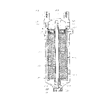
Referring now to Figure 3, a regenerative air dryer
system, generally designated 300, includes two desiccant canister
housing assemblies 200a and 200b of the type illustrated in
Figures 1 and 2. The regenerative air dryer system 300 installs
within a pneumatic system to clean and dry a stream of unpurified
air received from source of pressurized air. The air dryer system
300 includes an inlet manifold 310, a coalescing filter chamber
320, a first desiccant canister housing assembly 200a, a second
canister assembly housing 200b, an inlet check valve means 330, an
outlet manifold 390, an outlet check valve means 350, a purge
valve means 360 and controlling means 370.
The inlet manifold 310 defines a supply passage 311 for
receiving the stream of unpurified air from the source of
CA 02203305 1997-04-22
pressurized air (not shown) . The inlet manifold 310 also defines
first and second delivery passages, generally designated 312a and
312b, respectively. Similarly, the outlet manifold 340 defines
a first supply passage and a second supply passage, generally
designated 341a and 341b, respectively. Supply passage 341a
connects to delivery port 240a of first housing assembly 200a as
best shown in Figures 1 and 3. Similarly, supply passage 341b
connects to delivery port 240b of second housing assembly 200b.
The outlet manifold 340 also defines a delivery passage 342
through which a stream of cleaned and dried air is delivered to
the pneumatic system (not shown).
The coalescing filter chamber 320 initially separates
moisture and other particulates from the stream of unpurified air
received from supply passage 311 of inlet manifold 310 and
delivers a stream of initially filtered air to the delivery
passages 312a and 312b of inlet manifold 310. The filter
contained within the coalescing chamber 310 is preferably a
borosilicate filter.
The inlet check valve means 330 affects flow from first
312a and second 312b delivery passages of inlet manifold 310 to
first 200a and second 200b housing assemblies, respectively. The
inlet check valve means 330 includes first and second normally
open inlet check valves 330a and 330b. First inlet check valve
330a affects flow between first delivery passage 312a of inlet
manifold 310 and supply port 230a of first housing assembly 200a
as is best shown in Figures 1 and 3. Similarly, second inlet
11
CA 02203305 1997-04-22
check valve 330b affects flow between second delivery passage
312b of inlet manifold 310 and supply port 230b of second housing
assembly 200b.
The outlet check valve means 350 affects flow from
first 341a and second 341b supply passages of outlet manifold 340
to delivery passage 342 of outlet manifold 340. The outlet check
valve means 350 includes first and second normally open outlet
check valves 350a and 350b. First outlet check valve 350a
affects flow between first supply passage 341a of outlet manifold
340 and delivery passage 342 of outlet manifold 340. Similarly,
second outlet check valve 350b affects flow between second supply
passage 341b of outlet manifold 340 and delivery passage 342 of
outlet manifold 340.
The purge valve means 360 is a device through which
moisture previously collected in first 200a and second 200b
housing assemblies is expelled to atmosphere. The purge valve
means includes first and second normally closed purge valves 360a
and 360b. First purge valve 360a connects to purge port 25,Oa
defined through the lower base of first housing assembly 200a as
is best shown in Figures 1 and 3. Similarly, second purge valve
360b connects to purge port 250b defined through the lower base
of second housing assembly 200b. The regenerative gas dryer
system 300 also provides a drain valve means, generally
designated 380. The drain valve means 380 includes a normally
closed double seated drain valve 381 at the bottom of coalescing
filter chamber 320.
12
CA 02203305 1997-04-22
The controlling means 370 generally coordinates
operation of all of the valve means of the air dryer system 300
according to a preset operating cycle. During a first half of
the preset cycle, the valves of the air dryer system 300 are set
so that first desiccant canister housing 200a removes moisture
from the stream of initially filtered air while second desiccant
canister housing 200b is purged of moisture it has previously
collected. Specifically, first inlet check valve 330a and first
outlet check valve 350a are open and first purge valve 360a is
closed while second inlet check valve 330b and second outlet
check valve 350b are closed and second purge valve 360b is open.
The regenerative air dryer system 300 then generally operates as
follows. The stream of initially filtered air flows from
coalescing chamber 320 into first 312a and second 312b delivery
passages of inlet manifold 310. Because first and second inlet
valves 330a and 330b are open and closed, respectively, the
stream of initially filtered air flows only into first housing
assembly 200a through its supply port 230a as shown in Figures
1 and 3. First desiccant housing 200a extracts moisture from the
stream of initially filtered air. From first housing assembly
200a flows a first stream of purified air to a choke valve means,
generally designated 390, located between main portions 210a and
210b. Choke valve means 390 directs the first stream of purified
air in an output percentage to the pneumatic system and in a
purge percentage to second housing assembly 200b. The purge
percentage of the first stream of purified air flows through
13
CA 02203305 1997-04-22
second housing assembly 200b thereby reabsorbing the moisture
previously contained within its desiccant canister. This
remoisturized air stream then flows through purge port 250b and
purge valve 360b to atmosphere thereby regenerating second
housing assembly 200b f'or a second half of the preset cycle.
Meanwhile, the output percentage of the first stream of purified
air flows through delivery port 240a of first housing assembly
200a into first supply port 341a of outlet manifold 340. Because
first outlet check valve 350a is open, the output percentage of
the first stream of purified air flows through first supply 341a
and delivery 342 passages of outlet manifold 340 into the
pneumatic system.
During the second half of the preset cycle, the valves
--
of the air dryer system 300 are set so that second desiccant
canister housing 200b removes moisture from the stream of
initially filtered air while first desiccant canister housing
200a is purged of moisture it has previously collected.
Specifically, second inlet check valve 330b and second outlet
check valve 350b are open and second purge valve 360b is closed
while first inlet check valve 330a and first outlet check valve
350a are closed and first purge valve 360a is open. The
regenerative air dryer system 300 then generally operates as
follows. The stream of initially filtered air flows from
coalescing chamber 320 into first 312a and second 312b delivery
passages of inlet manifold 310. Because first and second inlet
valves 330a and 330b are closed and open, respectively, the
14
CA 02203305 1997-04-22
stream of initially filtered air flows only into second housing
assembly 200b through its supply port 230b as shown in Figures
1 and 3. Second desiccant housing 200b extracts moisture from
the stream of initially filtered air. From second housing
assembly 200b flows a second stream of purified air to choke
valve means 390 located between main portions 210a and 210b.
Choke valve means 390 directs the second stream of purified air
in an output percentage to the pneumatic system and in a purge
percentage to first housing assembly 200a. The purge percentage
of the second stream of purified air flows through first housing
assembly 200a thereby reabsorbing the moisture previously
contained within its desiccant canister. This remoisturized air
stream then flows through purge port 250a and purge valve 360a
to atmosphere thereby regenerating first housing assembly 200a
for the first half of the preset cycle. Meanwhile, the output
percentage of the second stream of purified air flows through
delivery port 240b of second housing assembly 200b into second
supply port 341b of outlet manifold 340. Because second outlet
check valve 350b is open, the output percentage of the second
stream of purified air flows through second supply 341b and
delivery 342 passages of outlet manifold 310 into the pneumatic
system.
The controlling means 370 thus controls the operation
of all the valve means so that the air dryer system 300
alternates between the first and second halves of the preset
operating cycle. Preferably, the preset operating cycle lasts
CA 02203305 1997-04-22
two minutes with one minute allocated for each half cycle. The
controlling means 370 also controls drain valve 381 situated at
the bottom of coalescing filter chamber 320 so that drain valve
381 opens briefly as the air dryer system 300 switches between
the first and second halves of the preset cycle. This permits
moisture previously collected in coalescing chamber 320 to be
expelled to atmosphere.
The controlling means 370 includes a first actuating
device, a second actuating device and an electronic controller
for controlling operation of the actuating devices. The first
actuating device controls operation of first inlet check valve
330a, first outlet check valve 350a, first purge valve 360a and
drain valve 381. The second actuating device controls operation
of second inlet check valve 330b, second outlet check valve 350b,
second purge valve 360b and drain valve 381. In the presently
preferred embodiment of the air dryer system, it is preferred
that each of the valves be of the air piloted variety.
Consequently, first actuating device is preferably a normally
closed three way solenoid valve for controlling supply of pilot
air to the valves under its control. Likewise, second actuating
device is preferably a normally closed three way solenoid valve
for controlling supply of pilot air to the valves under its
control. The electronic controller includes within its
electronic circuitry a timer circuit through which to control the
switching between the first and second halves of the preset
operating cycle.
16
, CA 02203305 2000-02-O1
The regenerative gas dryer system 300 further includes a
pressure sensor for sensing the pressure within the air dryer
system 300. When the pressure falls below a predetermined level,
the controlling means 370 allows all the valves to assume their
respective normally open or closed states. This will allow the
maximum amount of air to pass through the air dryer system 300
thereby reducing the time required to charge the pneumatic system
in which the air dryer system 300 is incorporated. Conversely,
when the pressure reaches or exceeds the predetermined level, the
controlling means 370 operates the air dryer system 300 according
to the preset operating cycle. The controlling means 370 will
generally not operate the air dryer system 300 according to the
preset operating cycle unless the pressure is generally equal to
or exceeds the predetermined level and the source of compressed
air is loaded.
The controlling means 370 also includes a memory
circuit. When the source of compressed air is loaded, the
controlling means 370 receives a signal that activates the memory
circuit. Through the memory circuit, equal drying and purging
times can be assured for each of the first and second housing
assemblies 200a and 200b. Specifically, the memory circuit
remembers the point within the preset operating cycle when the
source of compressed air becomes unloaded. The next time that the
source becomes loaded, the signal commences and the air dryer
system 300 resumes operation at the point in the preset operating
cycle at which it last operated.
17
CA 02203305 1997-04-22
The controlling means 370 also includes a power shut
off feature. When the supply of power to the controlling means
370 is cut off, the controlling means 370 will start at the
beginning of the preset operating cycle when power is restored.
This permits both the first and second desiccant canister housing
assemblies 200a and 200b to perform a complete cycle upon start-
up.
While the presently preferred embodiments of the
canister housing assembly invention and the air dryer system
incorporating same have been set forth in detail according to the
Patent Act, those persons of ordinary skill in the technical art
to which this invention pertains will recognize various
alternative ways of practicing the invention without departing
..-
from the spirit and scope of the appended claims. Those of
ordinary skill in the relevant art will also recognize that the
foregoing description is merely illustrative and is not intended
to limit any of the following claims to any particular narrow
interpretation.
Accordingly, to promote the progress of science and
useful arts, I secure for myself by Letters Patent exclusive
rights to all subject matter embraced by the following claims for
the time prescribed by the Patent Act.
18