Sélection de la langue

Search

Sommaire du brevet 2204457 

Énoncé de désistement de responsabilité concernant l'information provenant de tiers

Une partie des informations de ce site Web a été fournie par des sources externes. Le gouvernement du Canada n'assume aucune responsabilité concernant la précision, l'actualité ou la fiabilité des informations fournies par les sources externes. Les utilisateurs qui désirent employer cette information devraient consulter directement la source des informations. Le contenu fourni par les sources externes n'est pas assujetti aux exigences sur les langues officielles, la protection des renseignements personnels et l'accessibilité.

Disponibilité de l'Abrégé et des Revendications

L'apparition de différences dans le texte et l'image des Revendications et de l'Abrégé dépend du moment auquel le document est publié. Les textes des Revendications et de l'Abrégé sont affichés :

  • lorsque la demande peut être examinée par le public;
  • lorsque le brevet est émis (délivrance).
(12) Demande de brevet: (11) CA 2204457
(54) Titre français: PRISE DE COURANT ELECTRIQUE AVEC STRUCTURE DE COUVERCLE PIVOTANT
(54) Titre anglais: ELECTRICAL SOCKET WITH SWIVEL COVER STRUCTURE
Statut: Réputée abandonnée et au-delà du délai pour le rétablissement - en attente de la réponse à l’avis de communication rejetée
Données bibliographiques
Abrégés

Abrégé français

Une structure de prise de courant électrique avec une structure de couvercle pivotant comprend une plaque de base, une plaque de montage et une plaque pivotante. La plaque de base comporte deux fentes carrées symétriques ayant chacune une nervure aux bords supérieur et inférieur pour mise en prise sur la plaque de montage. La surface de la plaque de montage comporte un creux circulaire qui a deux trous de prise symétriques, avec une tige de fixation au centre. D'un côté de la tige de fixation, il y a un trou traversant dans lequel peut entrer un bout d'un ressort. Sur le pourtour du creux se trouvent deux rainures symétriques incurvées d'un quart de cercle. La plaque pivotante a deux trous de prise symétriques et est posée sur le creux de manière que le ressort se met en prise sur les encoches d'un manchon à sa face inférieure. On peut faire tourner la plaque pivotante pour cacher ou découvrir les trous de prise de la plaque de montage, et on peut fixer la plaque de base au bâti métallique pour une prise de courant classique.


Abrégé anglais


An electrical socket structure with a swivel cover
structure includes a base plate, a mounting plate and a
swivel plate. The base plate is provided with two
symmetrical square slots each of which has a rib at its
upper and lower edges for engaging the mounting plate.
The surface of the mounting plate is provided with a
circular recess which has a couple of symmetrical plug
holes, with a securing post at the center. At one side of
the securing post is a through hole into which one end of
a spring may insert. The periphery of the recess is
provided with two symmetrical curved grooves of a quadrant
of the circle. The swivel plate has a couple of
symmetrical plug holes and is fitted onto the recess such
that the spring engages the notches of a sleeve at a
bottom side thereof. The swivel plate may be turned to
conceal or expose the plug holes of the mounting plate,
and the base plate may be secured to the metal frame for a
conventional socket.

Revendications

Note : Les revendications sont présentées dans la langue officielle dans laquelle elles ont été soumises.


11
CLAIMS:
1. An electrical socket with a swivel cover
structure comprising:
a base plate, said base plate having with two
symmetrical square slots provided thereon, each
of said slots being provided with a rib at an
upper rim and a lower rim thereof, said base
plate further having a hook at each of the four
corners of the bottom side thereof;
a mounting plate of a size slightly smaller than
said slot, said mounting plate being provided
with a circular recess on an upper surface
thereof, said recess being biased to one side
of said mounting plate and provided with two
symmetrical plug holes, with a securing post of
a suitable height at the center, a through hole
and a curved elongated hole are respectively
formed at both sides of said securing post for
mounting of a spring, two symmetrical curved
grooves of a quadrant of the circumference of

12
said recess being formed at a periphery of said
recess, while two curved slide grooves are
formed at an inner rim of a vertical wall of
said recess; and
a swivel plate of a size slightly smaller than
said recess of said mounting plate, said swivel
plate having a plurality of plug holes
identical to said plug holes of said recess, a
plurality of symmetrical hooks being provided
at a periphery thereof, while two symmetrical
curved raised ribs are being provided at an
outer rim of a vertical wall thereof, with a
sleeve disposed at the center of a bottom side
thereof, said sleeve having two notches at an
opening thereof; whereby said swivel plate may
be fitted onto said recess of said mounting
plate such that said hooks thereof engage said
curved grooves at the periphery of said recess
to secure the connection; the two ends of said
spring pass through said notches of said sleeve

13
of said mounting plate for securing said
mounting plate in one of said slots of said
base plate; and said hooks of said base plate
engage a metal frame for a conventional socket;
said swivel plate being turnable, due to the
action of said spring, to close said plug holes
of said mounting plate or expose said plug
holes of said mounting plate for receiving a
plug.

Description

Note : Les descriptions sont présentées dans la langue officielle dans laquelle elles ont été soumises.

CA 022044~7 1997-0~-0~
TITLE: ELECTRICAL SOCKET WITH SWIVEL COVER STRUCTURE
BACRGROUND OF THE INVENTION
1. Field of the Invention
This invention relates generally to a socket
structure, and more particularly to a socket structure
with a swivel cover plate which may be turned to conceal
or expose the plug holes.
2. Description of the Prior Art
The plug holes in conventional electrical sockets are
often exposed on the outside, which is dangerous to
children. A socket structure for concealing the plug
holes when the socket is not in used is therefore
necessary.

CA 022044~7 1997-0~-0
SU~ARY OF THE INVENTION
This invention relates generally to a socket
structure, and more particularly to a socket structure
with a swivel cover plate which may be turned to conceal
or expose the plug holes.
According to first aspect of the present invention,
the present invention comprises a base plate for mounting
onto a metal frame for a conventional socket, the base
plate having a couple of symmetrical square slots, each of
which has a rib formed at an upper edge and a lower edge
thereof for engaging a mounting plate.
The mounting plate has a circular recess at the top
which is biased to one side. After a swivel plate is
fitted onto the recess, due to the action of a spring on
the recess, the swivel plate may be turned to conceal or
exposed the plug holes in in the mounting plate below.
The mounting plate may be reversely mounted to adjust the
distance between the plug holes for matching different
types of conventional sockets.
According to another aspect of the present invention,

CA 022044~7 1997-0~-0~
the periphery of the circular recess of the mounting plate
is provided with a pair of curved grooves of a quadrant of
the circumference of the circular recess, and the
periphery of the swivel plate is provided with hooks for
engaging the curved grooves of the mounting plate, whereby
the swivel plate may be secured on the recess and
positioned. Besides, assembly may be made easier.

CA 022044~7 1997-0~-0
BRIEF DESCRIPTION OF THE DRAWINGS
The invention is further described hereafter, by way
of example only, with reference to the accompanying
drawings, in which:
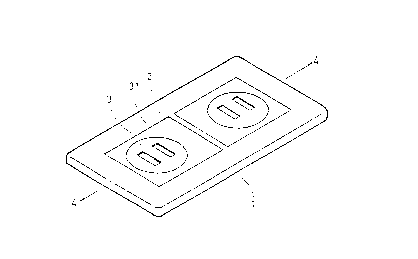
FIG. 1 is a schematic elevational view of the present
invention;
FIG. 2 is a schematic exploded view of the present
invention;
FIG. 3 is a schematic view of the structure of the
bottom side of the swivel plate of the present invention;
FIG. 4 is a schematic sectional view taken along line
4-4 of FIG. 1;
FIGS. 5A and 5B are schematic views illustrating
operation of the present invention; and
FIGS. 6A and 6B are schematic views illustrating the
present invention in use.

CA 022044~7 1997-0~-0~
DETAILED DESCRIPTION OF THE PREFERRED EMBODIMENT
For the purpose of promoting an understanding of the
principles of the invention, reference will now be made tD
the embodiment illustrated in the drawings. Specific
language will be used to describe same. It will,
nevertheless, be understood that no limitation of the
scope of the invention is thereby intended, such
alterations and further modifications in the illustrated
device, and such further applications of the principles of
the invention as illustrated herein being contemplated as
would normally occur to one skilled in the art to which
the invention relates.
With reference to FIGS. 1, 2 and 3, the present
invention essentially comprises a base plate 1, a pair of
mounting plates 2, and a pair of swivel plates 3. The
base plate 1 is provided with two symmetrical square slots
11 thereon. The upper and lower rims of each slot 11 are
respectively provided with a rib 111 projecting inwardly,
with the ends of each rib 111 cut suitably.
The mounting plates 2 are each provided with a couple

CA 022044~7 1997-0~-0~
of hooks 21 at the upper and lower edges thereof. Each
mounting plate 2 i8 mounted in the slot 11 such that the
hooks 21 engage the cut portions of the ribs 111 at the
upper and lower edges of the slot 11, thereby securing the
mounting plates 2 on the base plate 1.
The surface of each mounting plate 2 has a circular
recess 22 which is configured to bias to one side thereof.
Two symmetrical plug holes 221 are provided on the recess
22, with a securing post 222 of a suitable height is
disposed in the center of the recess between the plug
holes 221. A through hole 223 and a curved elongated
hole 224 i8 are respectively disposed at the sides of the
securing post 222. Two symmetrical curved grooves 225 of
a quadrant of the circular recess 22 is formed at the
periphery of the recess 22. A spring 23 is fitted over
the securing post 222 such that a bent end 231 thereof is
inserted into the through hole 223. The swivel plates 3
are then fitted onto the circular recesses 22 respectively
and may rotate therein by means of the spring 23.
The surface of the swivel plate 3 is provided with

CA 022044~7 1997-0~-0~
two symmetrical plug holes 31. The periphery of the
swivel plate 3 is provided with two symmetrical projecting
hooks 32 and two curved raised ribs 33 along the vertical
wall surface thereof such that, when the swivel plate 3 ls
fitted onto the circular recess 22 of the mounting plate
2, the hooks 32 may engage the curved grooves 225 to
secure the swivel plate 3 and position the turning of the
swivel plate 3.
When the swivel plate 3 is placed on the circular
recess 22, the ends of the spring 23 may be pushed by a
pointed objected via the curved elongated hole 224 on the
base 2 so that they respectively pass through the notches
341, 342 of a sleeve 34 at the center of the bottom side
of the swivel plate 3. Due to the tension of the spring
34, the plug holes 31 of the swivel plate 3 form a 90~
angle with the plug holes 221 of the mounting plate 2 to
conceal the plug holes 221 below. And since the swivel
plates 3 may be turned, the plug holes 31 and the plug
holes 221 may align to allow insertion of the plugs.
As shown in FIGS. 2 and 4, when the mounting plates

CA 022044~7 1997-0~-0~
2 are mounted into the slots ll of the base plate 1, the
hooks 21 of the mounting plates 2 respectively engage the
upper and lower rim~ of the slots 11 to secure the
connection. Furthermore, the inner periphery of the
circular recess 22 is provided with a couple of curved
slide grooves 226 so that, after the swivel plate 3 is
fitted onto the circular recess 22, the peripheral raised
ribs 33 may engage the curved slide grooves 226 to
prevent the swivel plate 3 from slipping out. The bottom
side of the base plate 1 is provided with two symmetrical
hooks 12 for engaging a conventional socket frame.
Referring to FIGS. 5A, 5B, 6A and 6B, when not in
use, the swivel plates are turned due to the action of the
spring 23 so that the plug holes 31 of the swivel plates 3
are at a 90~ angle to the plug holes 221 of the mounting
plates 2 to conceal the plug holes 221 below. When in
use, the pins 41 of a plug 4 are inserted into the plug
holes 31 of the swivel plates 3, and the swivel plates 3
are turned so that the plug holes 31 align with the plug
holes 221 to allow insertion of the pins 41 into the plug

CA 022044~7 1997-0~-0~
holes 221 below for electrical connection.
The distance between the plug holes of conventional
sockets may vary according to the type of the socket. In
the present invention, depending on the type of the
socket, the mounting plates 2 may be reversely fitted into
the slots 11 of the base plate 1 to improve the distance
between the swivel plates 3 and match different types of
conventional ~ockets.
In summary, the present invention provides adjustable
mounting plates for matching different types of
conventional sockets. Besides, the swivel plates may snap
into the mounting plates, making assembly easy and quick.
It will be understood that each of the elements
described above, or two or more together may also find a
useful application in other types of methods differing
from the type described above.
While certain novel features of this invention have
been shown and described and are pointed out in the
annexed claim, it is not intended to be limited to the
details above, since it will be understood that various

CA 022044~7 1997-0~-0
omissions, modifications, substitutions and changes in the
forms and details of the device illustrated and in its
operation can be made by those skilled in the art without
departing in any way from the spirit of the present
invention.
Without further analysis, the foregoing will so fully
reveal the gist of the present invention that others can,
by applying current knowledge, readily adapt it for
various applications without omitting features that, from
the standpoint of prior art, fairly constitute essential
characteristics of the generic or specific aspects of this
invention.

Dessin représentatif
Une figure unique qui représente un dessin illustrant l'invention.
États administratifs

2024-08-01 : Dans le cadre de la transition vers les Brevets de nouvelle génération (BNG), la base de données sur les brevets canadiens (BDBC) contient désormais un Historique d'événement plus détaillé, qui reproduit le Journal des événements de notre nouvelle solution interne.

Veuillez noter que les événements débutant par « Inactive : » se réfèrent à des événements qui ne sont plus utilisés dans notre nouvelle solution interne.

Pour une meilleure compréhension de l'état de la demande ou brevet qui figure sur cette page, la rubrique Mise en garde , et les descriptions de Brevet , Historique d'événement , Taxes périodiques et Historique des paiements devraient être consultées.

Historique d'événement

Description Date
Demande non rétablie avant l'échéance 2000-05-05
Le délai pour l'annulation est expiré 2000-05-05
Réputée abandonnée - omission de répondre à un avis sur les taxes pour le maintien en état 1999-05-05
Inactive : Correspondance - Formalités 1999-02-03
Demande publiée (accessible au public) 1998-11-05
Inactive : CIB en 1re position 1997-08-05
Inactive : CIB attribuée 1997-08-05
Inactive : Certificat de dépôt - Sans RE (Anglais) 1997-07-29
Exigences de dépôt - jugé conforme 1997-07-29

Historique d'abandonnement

Date d'abandonnement Raison Date de rétablissement
1999-05-05

Historique des taxes

Type de taxes Anniversaire Échéance Date payée
Taxe pour le dépôt - petite 1997-05-05
Titulaires au dossier

Les titulaires actuels et antérieures au dossier sont affichés en ordre alphabétique.

Titulaires actuels au dossier
JUNG-FU HSIAO
Titulaires antérieures au dossier
S.O.
Les propriétaires antérieurs qui ne figurent pas dans la liste des « Propriétaires au dossier » apparaîtront dans d'autres documents au dossier.
Documents

Pour visionner les fichiers sélectionnés, entrer le code reCAPTCHA :


Pour visualiser une image, cliquer sur un lien dans la colonne description du document. Pour télécharger l'image (les images), cliquer l'une ou plusieurs cases à cocher dans la première colonne et ensuite cliquer sur le bouton "Télécharger sélection en format PDF (archive Zip)" ou le bouton "Télécharger sélection (en un fichier PDF fusionné)".

Liste des documents de brevet publiés et non publiés sur la BDBC .

Si vous avez des difficultés à accéder au contenu, veuillez communiquer avec le Centre de services à la clientèle au 1-866-997-1936, ou envoyer un courriel au Centre de service à la clientèle de l'OPIC.


Description du
Document 
Date
(aaaa-mm-jj) 
Nombre de pages   Taille de l'image (Ko) 
Abrégé 1997-05-05 1 25
Revendications 1997-05-05 3 55
Description 1997-05-05 10 218
Dessins 1997-05-05 5 72
Page couverture 1999-01-12 1 54
Dessin représentatif 1999-01-12 1 6
Certificat de dépôt (anglais) 1997-07-29 1 164
Rappel de taxe de maintien due 1999-01-06 1 110
Courtoisie - Lettre d'abandon (taxe de maintien en état) 1999-06-02 1 186
Correspondance 1999-02-03 1 32