Note : Les descriptions sont présentées dans la langue officielle dans laquelle elles ont été soumises.
CA 0220~760 1997-0~-21
SPECIFICATlON
BACKGROUND OF TIIE lNVENTlON
~ield of the Invention
The invention relates to line bleed safety arrangements for hydraulic systems and in particular
to devices for providing a safe release of stored hydraulic energy.
Prior Art
It is a well known llazard to mechanics and techllicialls perforl~ lg servicing or mailltellallce
of a hydraulic sys~enl tllat lluid undcl plCSSUlC is vcly dall~clo~ls. Il~cidcl~ts involvillL~ SCliOUS hljllly
rrom a hydraulic leak are well knowll, such as whell a mecllallic or tcchlliciall hladvertelltly r ~IllS his
hand over a leaking fitting severing a finger or fingers, or bodily injuries as occur whell a systenl line
under higll pressure is opened, spraying fluid against the mecllanic or techniciall's skin. Numerous
such incidellts have occurred in wl~icll a nlecllallic or ~ecllnici~n llas released s~ored hydraulic cncrgy
fronl a line tllat was l)elieved to be at low or atnlosl)llel-ic pressulc. Cerlaillly a bcltcr WAy lllan thc
common practice of"cracking a connector" to release pressure is needed. The presellt invelltioll
provides a device for meeting tllis need that alFolds the nlccllallic or tecllniciall with a closed-loop
pressure bleed capability.
Heretofore a number of different configurations of devices and gauges have been provi(led
for sensing and measurillg a presence of fluid under pressure and exanlples of such are sllown in
patents to Kuter et al, U.S. Patellt No. 3,233,4G2; lo Schelllpp, U.S. l'atent No. 3,771,3G5 and ~o
saullla~ et al., U.S. I~alellt No. 4,727,753 willl a clleck valve devicc sllown il~ a palent to l~cJullasz,
U.S. Patent No. 2,547,377, that is for connectillg a pressure sensillg devices into a hydl-aulic system
CA 0220~760 1997-0~-21
line. Such systems and arrangement, unlike the present inventioll, whell hlstalled, may alert a
mechanic or teclmician to a presence of higl1 pressure, but they hAve not provided, as does the present
invention, for a safe and reliable system for conveniently releasing system pressure and to bleed fluid
back to a system reservoir, or the like, to avoid a loss of hydraulic fluid fi-om the system.
SUMMARY O~ Tl-IE INVENTION
lt is a principal object of the present invention hl a safety bleed assembly to provide a device
for connecting through pressure lines or hoses to check/bleed connectors that have been previously
installed in lines of a hydraulic system for safely relieving any trapped pressure from whicll lhles prior
to opening the system.
Another object of the present inventioll in a safety bleed assenlbly is to pl-ovide a halld held
device that is arranged for connection through lines to check/bleed conllector hlstalled hl lines or
hoses of a hydraulic system that may be under pressure to both determille a presence of pressure hl
the system and to vent such pressurized hydraulic lluid as is round in individual systen1 sections back
to a hydraulic systenl reservoir.
Still anotller object of the present invention in a safety bleed assenlbly is to pl ovide a device
for attachment into individual lilles of a llydraulic systenl tllat inclLI(lcs accull~ulatol s; coulltel balallcc
valves; pilot-operated check valves; actuators, and the like.
Still another object of the present inventioll in a safety bleed assenlbly is to provide a device
that is easy to use and preferably incorporates an arrangelnellt of color coded check valves and ports
wllereto are conl1ectc(1 cllds Orp~ss~gcs ror~-c(l i" a l)ody orlhc l~ d llcld l)rcssurc/l)lcc~l assclllbly,
the color coding to hldicate that the hldividual port is for couplillg to either a high or low pressure
CA 0220~760 1997-0~-21
line, respectively, and tl-e pOltS are, in turn, for connectioll thlou~ll lines or hoses to clleck/bleed
conneetors that have been fitted into l-ydraulic system lines or hoses that areunder pressure, for use
in relieving of system pressure and to drain hydraulic fluid therefrom back to a system reservoir.
Prineipal features of the safety bleed assembly of the invention include a halld held
pressure/bleed body wherein is formed at least one and preferably a pair of crossing passages that
open at the body sides and ends. A pressure gauge is connected into one passage end to receive and
indicate pressure as is present in the body, and at least one of tlle passage ends is rltted with a higll
pressure quick connect port for connection tllrough a line or l~ose to througll a check/bleed
eonnection mounted in a hydraulic system lligl~ pressure lil~e, and at least olle otller l~assage elld is
fitted with a low pressure quick col-nect port for conllectiol~ to a lille or llose ~o ven~ tluid tiom the
assembly housing back into a low pressure line of tlle hydraulic system tllat ultilnately vents to a
system reservoir. Preferably, a pair of lligh pressure quick conllect ports are rltted into passa~e ends
tllat each also inclLIde a check valve nloullled alongside each of tlle (luick conllec~ pol~s. The higll
pressure quick eonnect ports are preferal~ly arranged along one side Or tlle bo(ly and a pair of low
pressure quick comlect ports are moull~ed alongside one anotllel- ill the otller body side. Additionally,
a third high pressure quick connect port witll a check valve is pl eferably filled ill an elld of a passage
exiting tlle bottom of the body. The respective low and lligll pressure (luick collnect porls ar e eacll
preferably color coded, as, for example, the higll pressure ports are paillled r ed alld the low pressure
ports are painted blue. Such color codillg is to preclude a misallacl~ elll of a higll l~ressul-e lille or
llose to a low pressure port.
Witll all llle otl~er ,oorls capl)e~l, lor l)leedill~ a l~y(lraulic systeln, a pl essul e lille or Ilose is ~irst
connected to a low pressure port and into a check/bleed conllector tllat is located ill a low pressure
CA 0220~760 1997-0~-21
line of the hydraulic system. Thereafter, a pressure lille or llose end tllat has not been connected into
the hydraulic system is conllected into a lligl- pressure port of tlle asselnl~ly tllat is either a red bottom
port or one of the red side high pressure ports and the other line or hose end is tllen connected into
a check/bleed connector that is arranged in a lligh pressure line of the hydraulic system. In whicll
connection the connector is opened by operation of a valve release to pass fluid under pressure
tllerefrom that travels into and through the assembly body, exiting the low pressure port. Tlle higll
pressure ports each include a check valve that prohibits a back tlOw. Wllereas tlle low pressure ports
are open and must be capped whell not in use. ~owever, wllile the lligll pressure port or ports each
contain a check valve prohibitillg back llOw, such port, wllcll not in use, sllould be c~ppc(l, lo pl-ollibil
a flow of fluid therefrom. Tlle connectioll arrangelllent ror botll low alld higll pressul e lines of tlle
hydraulic system is preferably througll individual clleck/bleed connectors, each of wllicll is esselltially
a one way valve, that has previously been installed in critical portions or sections of the llydraulic
system.
DE~CRIPTION O~ Tl-lE DI~WINGS
In the drawings that represent the best mode presently contelllplated for carlyillg out tlle
invention:
Fig. 1 is a side elevation perspective view of a preferred elnbodimellt of tlle invelllioll in a
safety bleed assembly sllowillg a higll pressure line conllected OlltO a lower or bottonl l~igll ,oressure
port;
Fig. 2 is a front elevation sectiollal view taken along tlle lille 2 - 2 of Fig. I sllowing the
assembly body interior as containillg flow passages;
~ ~ CA 0220~760 1997-0~-21
Fig. 3 shows a schematic layout of a hydraulic actuator system Illat includes a connected
reservoir and system colnpollellts and is idenlified as prior art in tl1at it has not been configured to
receive the safety bleed assembly of liigs. 1 and 27 by an installalioll of higll pressure check/bleed
connectors into system lines or hoses;
Fig. 4 shows the schematic of Fig. 3 wherein have been added a number of checklbleed
connectors in lines or hoses of the system where pressure may be present and into lines or hoses
knowll to be at low pressure, and showillg a line or llose extendillg fi-onl a low pressure port of the
safety bleed assembly of Fig. 1 to vent fluid ultimately back to a sysleln reservoir, and sllowillg a
bottom high pressure pott of the safety bleed asseml)ly conllected into a line or llose that is between
a hydraulic system actuator, shown in a verlical altilude, and a coulltel- balance valve lhal nlay be
energized; and
Fig. 5 shows the scllematic of Fig. 3 whereill clleck/bleed collnectors llave been Inoullted and
sllowing tlle low pressul-e polt of tlle sarely blee(l assenlbly conllcclcd tllrougll a line or hosc to a low
pressure line to vent hydraulic fluid back to tlle system reservoir, an(l sllowil-g two side lligh prcssure
ports of the safety bleed asselllbly conllected, respectively, thlougll lines or hoses, between an
accumulator and a pressure relief valve and an actuator, sllown in a holizolllal a~litude~ and a
directional valve, respectively, illustl-atillg a use of the invelllioll for conllectillg systeln lligh prcssul e
lines or hoses to both the side high pressure ports for ventillg sepal-ate hydl-alllic systenl lines.
DETAlLED DESCRIPTION
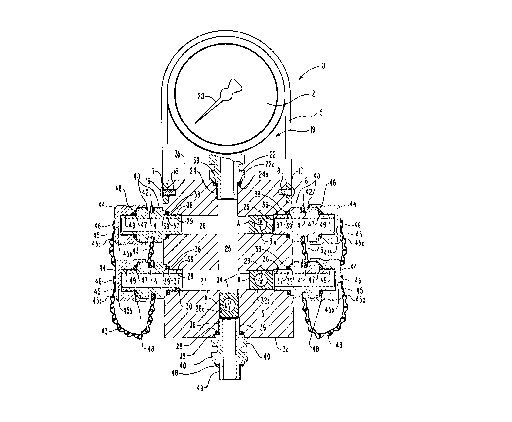
The illventioll in ~ s~rely blced asscmbly lo, llcrcil~artcr rcrcl-l-cd lo as blcc(l asscll1bly, is
sllown best itl Figs. I alld 2. The bleed asselnbly 10 is prcferably ror collnectioll into lines or lloses
CA 0220~760 1997-0~-21
of a hydraulic system G0, ShOWII ill Figs. 4 and 5, lllat has been rllted Willl ClleCk/bleed COnlleCtiOnS
to cormect through lines or hoses 51 to tlle bleed assembly 10. The hydraulic system 60 before it is
configured to connect to the bleed assembly 10, is shown in Fig. 3, whicll Figure is here identified as
prior art. Shown in Fig. 1, the bleed assembly 10 includes a housing 12, sllown as a rectangular block
body 13, that preferably includes, on a fi-ollt face 13a, a card 14 containil-g instructions, cautions, and
the like, thereon that relate to operation of tlle bleed assembly. Tlle plate 14 is, of course, an optional
inclusion and the instructions and cautions, as sllowll, are here provided as examples only of
information as may be written thereon. Showl- in Figs. I and 2, a protective cover 15, tllat is sl~own
formed as an arch to extend over the block top end 1 3b, is conllec~ed at its ends to tlle body 13 1~l-
end as by fitting screws 16 tllrougll hotes 17 that llave been roll~led tllroll~ll tlle cover 15 cnd secliolls
and are turned into threaded holes 18 fonned into the body. Tlle l~rotective cover 15 is fit over to
nlaintaill a pressure ~au~e 19, tllat is l)relclably a convellliollal ~a~lge as is sui~able rOI- nleasurillg
nuids under pressure. Such gauge is pl-crel-ably a glycerille filled Bourdon lube typc gauge ll)at is
capable of measuring pressures of from 0 to 3,000 psi and a gauge manufactured by Lenz Corp.,
identified as a pressure gauge, has been used successfully for tlle invelllioll. Tlle gauge is read by an
operator observing positioning of a piVOtillg radial arm 20 tunled over a scale 21, as sllowll hl liigs.
I an(l 2. 'I hc pressul e lllat is rea(l olr of lllc gaugc 15 is Illc l~rcsslll C \v~ c l-o(ly 1~ cll ll~c
assembly 10 is connected throu~h a line or hose 5 I to a line, lube or hose of a section Or hydlaulic
systen- 60. To couple tlle pressure gauge into tlle body 13, a gauge stem 22 is provided tllat is
thl-eaded at 23 and is sleppcd outwal-dly al 22a inlo a sllclf abovc tllc lln-cads, tllat is lul-llcd illlo a
tllreadc-l opcnill~ 24 rorlllcd inlO lllc l)ody lop cnd 1 3b. I llc OpCllil)g 24, as sllown, is ilscll' slcppcd
outwardly into a seat 24a to contain an O - ring 39, as sllown in l~ig. 2. l he O - ring is for sealing
CA 0220~760 1997-0~-21
the gauge stem 22 in the opening 24 against fluid leakage. The threaded oyening 24 is at tlle top end
of an open center vertical passage 25 that is formed tllrougll the body 13 and extends froln top end
13b to bottom end 13c.
Shown in Fig. 2, tlle body 13, in addition to the center vertical passage 25, preferably includes
a pair of parallel open horizontal top and bottom passages 26 and 27, respectively, tllat are spaced
apan from one another and are formed to cross and open into the center vertical passage 25. Like
the threaded top end 24 of center vertical passage 25, the opposite or lower vertical passage 25 end
28 is also threaded, as are tlle horizolltal passage 26 and 27 ends 29, 30, 31, and 32, resl~ectively.
[;urther, each passage end is s~cppcd oulwaldly illto a sllelf lllat is lo scrve as a scal 38 I'or rcccivi
an O - ring 39. The vertical passage lower end 28 and the horizolllal passage tllreaded ends 31 and
32, respectively, are arrallged as lligh pressure ports for conllectioll to higll pressure sources and
accordingly are each s~epped slightly inwardly alld tllreaded at 28a, 3 la alld 32a, respectively, for
receiving a check valve 34 tul-lled tllereil-. T he check valves 34 are ,~rovi(led ~o check or prol~ibit
flow out of the passages, as illustrated by small arrows A, witll eacl~ clleck valve turned into the
passage end ahead of a port 35 fitted thereill. Ports 35 are preferably alike and each is for fitting into
a body passage threaded opening. Accordillgly, the ports may be tlle same nlallllfaclule, or of
di~erent manufacture w~ the scope of lllis disclosure. ln praclicc, a cllcck valvc 34, Inallut~iclul cd
by Kepner Product Co. identified as a clleck valve, has beell used successrully t'or tlle invelltioll, as
has a port 35 manufactured by Kepner Product Co., identified as a clleck valve, thougll, of course,
other check valves and pol-ls manufac~ured by o~llers could be so use(l witllill the scol~e of this
invelltion .
CA 0220~760 1997-0~-21
The respective pOltS 35, as showll in Figs. 1 and 2, adjacellt to a threaded neck 36 of each are
stepped outwardly into a shelf 37. The shelf 37 is to align witll lhe seat 38 that is formed aroulld an
outer edge of each of the passages, 25, 26, and 27, respectively, with the area between the shelf 37
and seat 38 to contain O- ring 39. The O - ring 39, as described above with respect to gauge port
22, is preferably like and may be the same manufacture as port 35. So arranged, when a port 3 5 or
gauge port 22 is turned into the threaded end of the passages 25, 26, and 27, the respective port
shelves 37 and gauge port shelf 22a, respectively, compress the O - rillg 39 agaillst the seat 3 8 and
fitting seat 24a, respectively. The ports 35 and fitting 22, res,~ectively, are thereby sealed itl the ends
24, 28, 29, 30, 31, and 32, of the vertical and holizolllal passages 25, 26, and 27, respeclive
prohibiting leakage of fluid under pressure therefi-om.
The ports 35 that are secured over the ends 28, 29, 30, 31, and 32 of the vertical and
horizontal passages 25, 26, and 27, respectively, are each showll to have a sided outer body surface
40, shown herein as a hexagon cross section, for receivin~ a collventiollal wrencll fitted thereto, or
the like, that is ror turlling the port into a passage end. Preferably, a center slot 41 is forlned into
each of the sided surfaces that is for receiving a mounting tab 42 fitted therein. Each Inoulltillg tab
42 is shown to include a hole 42a formed tllrougll i~s end wllere~hrougll an end of a chaill 43 is sllown
secured with tlle chaill opposile end collllectcd illlo a llole 45a tll~ s l~cell rol-lllcd lllrou~ n oulcr
end of a bar 45. The bar 45 is, in turn, conllected, at its head end 45b to a center of a screw oll cap
44, as by a rivet 46. Shown in Fig. 2, each cap 44 is arranged to receive all inllel- O - rit-g 47 mounted
thereill that is ror engagillg a port outel shelr48 to seal tllereagainst wllen the cap is tightelled OlltO
to close o~a port tllreaded outer elld 49. So arrallgcd, wi~ c caps 44 sccurcd olllo tl~c pOlt 35
threaded ends 49, the body 13 will be pressure tight. Showll in Fig. 1, with the bleed assenlbly
. CA 0220~760 1997-0~-21
connected at port 35, to a hose 51 that contains fluid under pressure, and wiell the caps 44 fitted over
tl~e other ports 35, as ShOWIl ill ~igs. I and 2, pressure in line 51 will bc displayed on pressure gauge
19.
The respective ports 35 that are arranged, respectively, in the end 28 of vertical passage 25
and the ends 31 and 32 of the horizontal passages 26 and 27 each follow a check valve 34 that has
been turned therein. So arranged, the ports 35 and check valves 34 function as higll pressure inlet
ports. The check valves 34 are each a one way valve, constructed to allow luid under pressure to
pass into a passage but prohibitillg a back nOw therethl-ougll, as illustra~ed by arl-ow i~. Distinct
therefrom, the ports 35 tllat are fitted into horizolltal passage 26 alld 27 ClldS 29 and 30, respectively
are designated as low pressure ports tl~at are opell theletlllougll to allow a free llow OUt r~-O~ llc
body 13. So arranged, the ports 35 maintained in passage ends 28,31, and 32 that illClUde the
described check valves 34 are higll pressure ports that are hltellded to be connected hlto hydraulic
system lines or hoses for passing fluid under pressure tllerefrom. Tlle port and caps are preferably
color coded, as are check/bleed conllectors 61 of the hydraulic system G0 wllereto they are conllected,
to identify an operator their function. In practice these ports, caps and conlleclors are painted red
to indicate danger. Whereas, the ports 35 mounted hl passage ends 29 alld 30, that do not include
check valves 34, are set out as behlg low pressure ports and are also color coded as are theil- caps,
and the check/bleed conllectors 62 of the hydraulic system 60 whel-eto they are conllecled 'I hese
ports, caps and connectors, as set out, are ror conllectioll to draill fluid rrOn~ tlle bleed asselllbly 10
into a low pressure line that ultinlately collnecls to pass fluid back into a systenl resel-voir, or the like.
In practice tlle low pressure ports 35, their caps, and clleck/bleed conlleclors 62, are preferably
painted blue to identify thelll as low pressure ports.
CA 0220~760 1997-0~-21
Fig. 3, identified as prior art, shows a schelllatic of a hydraulic system 60 before it llas been
conffgured to connect to the bleed assembly 10 of the invelllioll. I;igs. 4 and 5, as set out and
described hereinbelow, show the same hydraulic system 60 aller it has been altered by an inclusioll
the of checklbleed conllectors 61 in system high pressure lines as may remaill in a pressurized state
after the hydraulic system is sllut off, and witll low pressure check/bleed connectors62 collllectedillto
lines that are known to be at zero or low pressure that are for connectioll to lines or hoses that
ultimately drain fluid back into a system reservoir 63. The check/bleed connectors 6l and 62 are
preferably standard check valve type componellts as are utilized in llydraulic systenls to contain
pressure witllin a hydraulic line until released by receipt of an applopliate lille or llose rlltillg 52
turned thereon. For the invention check/bleed conllectors knowll as a coupling, malluractured by
Stautt Corp., have been used successfully as hose conllectors 52, and are arranged for comlectillg to
ends of lines or hoses Sl, as set out above and described in detail llereillbelow. l lle hose conlleclor
52iS arranged to fit onto a check/bleed connector 61 or 62,and preferably includes a center stem,
or the like, not shown, that is to fit into the stem or neck of a check/bleed connector G 1 or62. Tlle
filting of the hose comlector stem onto the checklbleed conllec~or neck opells a valve pO11iOIl of the
connector neck, not showll, to pass contail1ed Iluid ullder pressule.
The bleed assembly 10 of tlle invelltioll is for arrangelllelll ill a typical llydraulic syslelll 60,
like that shown in Fig. 3. Which hydraulic system 60 is ShOWIl ill Figs 4 and 5, as havillg been
modified to include check/bleed conllectors 61 in lines or lloses of tlle hydl-aulic systelll 60 of ~ig. 3
wherein a pressurized state may exist al~er system shutdown, witll check/bleed conllectors62 sllowll
rltted into low l~ressure lines. So arlall~,e~l, blecd assenlbly 10 l~ )ressure ports 35 can be
conllected througll lines or hoses 51 to clleck/bleed conlleclol-s 61 to vent or bleed lluid ullder
CA 0220~760 1997-0~-21
pressure through the bleed assembly 10 that passes thererrom out low pressure ports 35, through lines
or hoses 51, and into low pressure check/bleed conllectol s 62 arrallgcd hl low pressure scctions of
the hydraulic system 60. Prior to whicll connection of such check/bleed conllector 61 througl1 line
or hose 51 to a bleed assembly 10 higll pressure port 35, a line or hose 51 is first conllected betweell
bleed assembly 10 low pressure port 35 and a low pressure check/bleed conllector 62 mailltained in
a low pressure line of the hydraulic system 60, to pass fluid back into system reservoir 63 . With the
low pressure side of the bleed assembly 10 so connected, as showll hl Fig. 4, and witll the other low
pressure port 3 5 closed off by a cap 44, a higll pressure port 35 can be conllected througll line or hose
51, to a checktbleed connector 61 that is arranged ill a hydlaulic systeln 60 Ihle or hose that may be
under pressure, for VClltillg hydraulic energy tllrougll the l~lccd asscllll~ly 10 and back to lhe Systc
reservoir 63.
The hydraulic system 60, as SllOWIl in Figs. 3 through 5, includes a vertical actuator G5 and
a horizontal actuator 66 whereto lines or hoses are connec~ed into both top ends 67 and 68,
respectively, and bottom ends 69 and 70, respectively, the actuators operated on receipt of fluid under
pressure, to move piStOllS 71 and 72, respectively. The vertical actuator 65 lower end 69 is shown
pressurized through a counter balance valve 73 that, UpOIl system sllut ofF, will llold pressure to
maintain the piston 71 in an extended attitude. So arranged, even aRer sllutdowll of ~lle hydl-aulic
system 60, fluid under pressure will remain in this line or llose. ln l~ig. 4, sections of tlle hydraLIlic
system 60 are shown comlected through Ihles or lloses 51 to the bleed assenlbly l o of tlle invell~ioll~
Shown therein, a line or hose is maintailled between the vertical actuator bottom end 69 and counter
l~alance valve 73 ror vellthlg [luid undcr l~ressul-e thcrcrl-oltl lo 1~5~5 Il~l-ou~ll the blecd ~ssen~l)ly 10
line or hose 51 and exithlg a low pressure connector 62 port to Ilow thl-ougll a second filter 85 hlto
- CA 0220~760 1997-0~-21
a low pressure check/bleed connector 62 located between a filter 85 and heat exchatlger 86 to
ltim~t~ly pass back into a system reservoir 63 Additional locations whereitl high pressure may exist
after system sllut down are sections between horizontal actuator 66 top and bottom ends 68 are
shown connected to pilot operated valves 74 that, in turn, are connected together by a cross pipe 75
and are, in turn, connected by lines or hoses to one of a pair of directional valves 76 So arranged,
fluid under pressure may be trapped on eitller side of the pilot operated valves Lines or hoses that
contain trapped fluid are also shown connecting the counter balance valve 73 and top end 67 of the
vertical actuator 65 to another pair of directional valves 76 that, as sllowll, are moullted onto a block
77 The pilot operated valves 74 and cross pipe 75, may colltail~ pressul-e tra,l)ped l)etweel~ tlle
horizontal actuator and sucll COlllpOl1Cllt all(l accoldill~sly a cllcck/l)lcc~l COllllCClOI- 61, llol sl~o\vl~ y
be connected in the line or hose from tlle horizolltal actuator 66 and pilot clleck valve 74 to meet a
potential lleed to vent ~ressure from tllis section of llydraulic systenl 60
Tlle lines or lloses that colinect illtO tlle (lireclional valves 76 Illay also be ullder pressure and
a check/bleed connectioll 61 is shown fitted into eacll line for ventillg tllat line or l~ose individually,
as set out hereinbelow witll respect to a discussion of Fig 5 Figs 4 and 5 sllow a vent lille or hose
that is cormected to provide a flow out of block 77 and tllrough the filter 85 witll tllat collnects to a
heat excllanger 86, that is a low pressure seclion or l~OI-tiOIl of lly(lralllic syslelll 60 l lle h
exchan~er 86, in turn, is conllected l)y a lille or llose to ven~ flui(J l~ack to rlller 85 lllcll lo resel-voil
63. During operation of the hydraulic system 60, afler the actuators 65 and GG al~e fully ~ressul~ized,
tlle directional valves 76 are operated to direct nuid througll rllter 85, and ill~O llle heat exchanger 86
tllat is at low or zero pless-lle l'ur coolill~ al~d to llow back to tl~e rcsclvoil G3 Witll tl~e l)ydraulic
system shut down, the directional valves 76 may be positioned to retaill pl-essul-e in a line or hose to
CA 0220~760 1997-0~-21
an ~ccllmlll~tor 78 and from the accumulator a T connector 79 that is preferably open tlleretllrough,
and accordingly a check/bleed coJmector 61 is fitted in this line. In l~ig. 5, a line or hose 51 is shown
connected into tl1e check/bleed colmec~ion 61 to pass fluid lhrougll the bleed assembly l0 and to a
low pressure check/bleed connector 62 that is upstream from the heat exchal1ger 86. So arranged,
fluid as contained in the hydraulic system 60 between the directional valves 76 on block 77 and a
pressure reliefvalve 80 is vented through the bleed assembly 10.
From the pressure relief valve 80 the hydraulic system divides into IlOw paths tllat connect,
respectively, to a low pressure line wherein a low pressure check/bleed collnector 62 is fitted to vent
to the reservoir 63, and througll a check valve 84 to a pUlllp ~ l tllat is operated by a collllected
motor, shown as a broken line box 82, to turn a punlp shal~83. ïlle outl~ut Or punlp 81is to travel
through a check valve 84 and to the pressure relief valve 80. Accordingly, even with the pump 81
stopped, as by a turllill~ olrof tlle lllo~or 82, pressure nlay still cxist between tlle pressure relief valve
80 and check valve 84 and accordingly a lligll pressure check/bleed valve 61, not shown, is preferably
included therebetween.
As set out above, Figs. 4and5sllow a typical hydraulic system 60 whereill lines or hoses may
contain fluid under pressure after a pump 81 has been shut o~, and wllerein lligh pressure clleck/l~leed
valves 61 are installed and with low ple~sule chcck/bleed collllectors 62 rlltcd in lillcs Or lloscs lll;ll
are at zero or low pressure, with fluid therein ultimately draillillg back to resel-voir 63. lt sllould be
understood that the hydraulic system 60 is shown herein for illustratioll only, and tlle invelltioll is ill
the bleed assenlbly l0 that is not limited for use with any particular l~ydraulic system. Except, of
COUl sc, ally llydraulic Syslclll to bc vcnlcd by ll)c blccd asscnlbly nlus~ bc r~ltc(l witl) l~ ll and low
pressure check/bleed con-lectols 61 and 62. Itl practice, the connection of tlle bleed assenlbly 10 first
14
CA 0220~760 1997-0~-21
to low pressure checklbleed connectors 62 and then tllrougll individual check/bleed conllectors 61
contillues aroulld tlle hydraulic system 60 unlil all tlle sectiolls tllereortllat could contaill lluid under
pressure have been vented l~ack to reservoir 63. Whereaner, tlle entile llydraulic systelll 60 can be
safely opened for repair or replacement of individual components.
While a preferred embodiment of my invention in a bleed assembly for installatioll in a
hydraulic system that has been appropriately modified to receive the bleed assembly connected thereill
for bleeding or relieving pressure fi-om sections of the hydraulic system has been sllowll and described
herein. It should, however, be understood that the present disclosure is made by way of example
only and that the invention may be configured and operated differelltly thall as showll and described
without departing from the subject matter coming witllill the scope of the followhlg claims, and a
reasonable equivalency thereof, WhiCIl claims 1 regard as my hlvelltioll.