Note : Les descriptions sont présentées dans la langue officielle dans laquelle elles ont été soumises.
CA 02207506 1997-06-10
Doc No. FYP 386 CA Patent
DISPERSION COMPENSATING FIBER AND ITS MANUFACTURING METHOD
FIELD OF THE INVENTION
The present invention relates to a dispersion
compensating fiber for compensating for dispersion caused in
optical communications performed at a wavelength of 1.55~m by
use of an optical fiber having zero dispersion at a wavelength
of 1 . 3~m.
1o
BACKGROUND OF THE INVENTION
In recent years, it has been under study to perform a
long-haul large-capacity transmission by use of an optical
signal with a wavelength of 1.55~m which is considered to be
transmitted with the lowest losses in theory. Presently
installed optical transmission lines, i.e. existing optical
transmission lines are constructed of single-mode optical
fibers. The dispersion wavelength characteristic of the
single-mode optical fiber is such that dispersion is zero at a
wavelength of 1.3~m and increases as the wavelength increases
or decreases from 1.3~.m. At a wavelength of 1.55~,m, a great
positive dispersion is caused. Therefore, when light with a
wavelength of 1.55~..~m is transmitted over existing transmission
lines constructed of single-mode optical fibers designed to
transmit at wavelengths of 1.3~,m, the waveform is distorted.
In order to compensate for the dispersion of the single-mode
optical fiber at a wavelength of 1.55~m, it is attempted to
cancel the dispersion by inserting a dispersion compensating
fiber having at a wavelength of 1.55~..~.m a great dispersion of a
1
CA 02207506 1997-06-10
Doo No. FYP 386 CA Pafent
sign opposite to that of the above-mentioned dispersion, that
is, a large negative dispersion.
To obtain a great negative dispersion, the difference
between the refractive indices of the core and the cladding
needs to be extremely large or the diameter of the core needs
to be extremely small compared with the single-mode optical
fiber. If the diameter of the core is extremely small, level
difference is caused at the connection with the single-mode
to optical fibers, so that problems arise such as an increase in
splice loss. Therefore, a dispersion compensating fiber is
commonly used which has a profile of a high refractive index
difference structure between the refractive indices of the
core and the cladding.
In a dispersion compensating fiber having the high
refractive index difference structure, the refractive index
adjuster (GeCl4) for increasing the refractive index of the
core is doped by frame-hydrolyzing the adjuster together with
the glass material (SiCl4) gas, and the fluorine for
decreasing the refractive index of the cladding is doped by
vitrifying a porous cladding material in an atmosphere
including fluorine. Therefore, if the core and the cladding
are simultaneously synthesized like the single-mode optical
fiber, the fluorine is doped not only in the cladding but also
in the core in the vitrification, so that the profile of the
high refractive index structure cannot be obtained. Thus, for
dispersion compensating fiber, it is impossible to
simultaneously synthesize the core and the cladding (for the
single-mode optical fiber, generally, the core and a part of
the cladding are simultaneously produced by the vapor axial
deposition (VAD) method).
2
CA 02207506 1997-06-10
Doc I~To. FYP 386 CA Patent
Therefore, the dispersion compensating fiber is
manufactured in the following manner. First, a silica-based
porous core material formed only of silica-based glass (core
composition) doped with germanium is synthesized by a known
method such as the VAD method, and then, the core material is
dehydrated and sintered to form a core rod material. Then,
after the core rod material is stretched so as to have a
predetermined diameter to form a core rod, a silica-based
porous cladding layer is deposited on the periphery of the
core rod. Then, the core rod is dehydrated and sintered in an
atmosphere including fluorine to obtain a glass material. By
melt-spinning the glass material, the dispersion-compensating
fiber is obtained.
According to the dispersion compensating fiber
manufacturing method, prior to the deposition of the silica-
based porous cladding layer constituting the cladding on the
core rod, an OH radical and the like which adhered to the
surface of the core rod in the stretching process is removed
by grinding by a chemical or a physical technique. To suppress
polarization mode dispersion (PMD), it is required that the
cross-sectional profile of the dispersion-compensating fiber
be symmetrical. The symmetry is required particularly of the
profile of the core; in fact, it is desired that the profile
of the core be substantially completely symmetrical. For this
reason, in order to shape the profile of the core, the surface
of the core rod is sometimes ground more than necessary for
removing the OH radial and the like.
OBJECT AND STJi~ARY OF THE INVENTION
3
CA 02207506 1997-06-10
Doc No. FYP 386 CA Patent
However, it has been found that in dispersion
compensating fiber having undergone the core rod surface
grinding process during manufacturing, a polarization mode
dispersion which is great compared with that caused in a
dispersion compensating fiber not having undergone the core
rod surface grinding process during manufacturing is caused
due to the birefringence of the core.
Polarization mode dispersion is a great barrier in increasing
the speed of long-haul optical communication systems.
In view of the problem, an object of the present
invention is to provide a structure of a dispersion
compensating fiber capable of suppressing the generation of
the polarization mode dispersion, and its manufacturing
method.
According to a first aspect of the present invention, a
dispersion compensating fiber is provided that comprises a
silica glass core doped with germanium and a silica glass
cladding doped with fluorine, said cladding being provided to
surround the core, a variation in circumferential
concentration of germanium at a periphery of a center core
situated in a center of the silica glass core is 0.050 or
smaller in refractive index difference value.
According to a second aspect of the present invention, a
dispersion compensating fiber is provided comprising a silica
glass center core doped with germanium, a silica glass side
core doped with fluorine and a silica glass cladding, said
side core being provided to surround the center core, said
cladding being provided to surround the side core, a variation
4
CA 02207506 1997-06-10
Doc No. FYP 386 CA Patent
in circumferential concentration of germanium at a periphery
of the center core situated in a center of a silica glass core
is 0.050 or smaller in relative refractive index difference
value.
According to a third aspect of the present invention,
after a variation in circumferential concentration of
germanium at a periphery of a core rod obtained by dehydrating
and sintering a silica-based porous core material doped with
germanium is set at 0.050 or smaller in relative refractive
index difference value, a silica-based porous cladding layer
doped with fluorine is deposited to surround the core rod, and
then, the core rod is dehydrated and sintered to obtain a
glass material which is then melt-spun.
In the dispersion compensating fiber according to the
first and second aspects of the present invention which is
manufactured so that the variation in circumferential
concentration of germanium at the periphery of the center core
is 0.05% or smaller in relative refractive index difference
value, the birefringence of the core caused in spinning is
reduced, so that the value of the polarization mode dispersion
due to the birefringence of the core is reduced to 0.1
ps/(km»-1~2~ or lower. This enables high-quality large-capacity
optical transmission.
According to the third aspect of the present invention,
since the cladding layer is formed after the variation in
circumferential concentration of germanium at the periphery of
the core rod obtained by dehydrating and sintering the silica-
based porous core material is set at 0.050 or smaller in
relative refractive index difference value, when the
5
CA 02207506 1997-06-10
Doc No. FYP 386 CA Patent
temperature of the dispersion compensating fiber obtained by
fiber-drawing the glass material is changed from the melt
fiber drawing (spinning) temperature to the normal
temperature, the residual stress attributed to the difference
in°expansion coefficient caused due to the difference in
circumferential viscosity of a portion of the core in the
vicinity of the cladding substantially equals zero, so that
the core, particularly the portion of the core in the vicinity
of the cladding is prevented from receiving circumferentially
nonuniform tension. This largely reduces the birefringence of
the core caused in spinning even when the grinding is
performed to shape the profile of the core, so that the
polarization mode dispersion due to the birefringence is
reduced. As a result, high-quality large-capacity optical
transmission is enabled as mentioned above.
BRIEF DESCRIPTION OF THE DRAWINGS
These and other objects and advantages of the present
invention will become more apparent and more readily
appreciated from the following detailed description of the
exemplary embodiments of the invention, taken in conjunction
with the accompanying drawings, in which:
FIG. 1 is a graph showing a relationship between a
variation in relative refractive index difference and the
magnitude of the polarization mode dispersion at the periphery
of the core;
FIG. 2 is a schematic view showing a refractive index
profile of a dispersion-compensating fiber according to the
present invention;
6
CA 02207506 1997-06-10
Doc I~Io. FYP 386 CA Patent
FIG. 3 is a view showing a stepped refractive index
profile of the dispersion compensating fiber according to the
present invention; and
FIG. 4 is a view showing a W-shaped refractive index
profile of the dispersion-compensating fiber according to the
present invention.
DETAINED DESCRIPTION
Hereinafter, an embodiment of the present invention will
be described in detail with reference to the drawings.
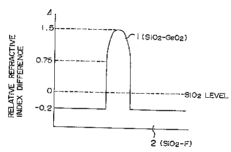
FIG. 2 shows an example of a refractive index profile of
a dispersion-compensating fiber according to the present
invention. The refractive index profile shown in FIG. 2 is
unimodal. A core (center core) 1 having the highest refractive
index is surrounded by a cladding 2 having a low refractive
index. When the refractive index of silica is n0, a relative
refractive index difference O of a portion having a refractive
power n with respect to silica (Si02) is obtained by O = {(n2-
noz)/2n2}x 100. The vertical axis of FIG. 2 shows a relative
refractive index difference with respect to silica.
A coefficient a, representative of the refractive index
profile configuration of the center core 1 is oc=2. In the core
formed region, germanium is doped so that the relative
refractive index difference at the center of the center core 1
is Otop = 1.5o and that the relative refractive index
difference at the periphery of the center core is Obottom =
0.750 (circumferential average value). In the cladding 2,
7
CA 02207506 1997-06-10
Doc I~Io. FYP 386 CA Patent
fluorine is uniformly doped so that a relative refractive
index difference ~F with respect to silica is OF = -0.20.
The inventors thought that in the dispersion-compensating
fiber, the magnitude of the polarization mode dispersion
caused in transmitting optical signals might be related to a
variation in circumferential relative refractive index
difference at the periphery of the core 1, and produced a
multiplicity of dispersion compensating fibers as test samples
l0 in the following manner: First, a silica-based porous core
material produced by doping germanium by the VAD method was
dehydrated and sintered to form a core rod. Then, the surface
of the core rod was ground under different conditions to
adjust the circumferential concentration of germanium in the
vicinity of periphery of the core rod. Then, after the
cladding layer was formed by the outside vapor phase
deposition method, the core rod was dehydrated and sintered to
obtain a glass material. The glass material was fiber-drawn by
a known method to thereby obtain dispersion compensating
fibers having various magnitudes of variations in
circumferential relative refractive index difference at the
periphery of the core 1.
Then, the polarization mode dispersion was measured for
each test sample of the dispersion-compensating fiber to
obtain a relationship as shown in FIG. 1. In FIG. l, the
horizontal axis represents the difference between the maximum
and minimum values of the circumferential relative refractive
index difference of the core 1 as a variation in refractive
index difference, and the vertical axis represents the
polarization mode dispersion. As is apparent from FIG. l, when
the variation in circumferential concentration of germanium at
8
CA 02207506 1997-06-10
Doc No. FYP 386 CA Patent
the periphery of the core (the difference between the maximum
and minimum values of the circumferential concentration of
germanium of the core) of the dispersion compensating fiber
exceeds 0.050 in relative refractive index difference value,
the polarization mode dispersion abruptly increases and
exceeds 0.1 ps/(km)(-1/2) which the inventors consider as the
criterion of quality assurance for ensuring excellent large-
capacity optical transmission. Thus, it was found that in
order to obtain a dispersion compensating fiber of excellent
quality, the variation in circumferential concentration of
germanium needs to be 0.05% or smaller in relative refractive
index difference value.
The grinding by a chemical technique in producing the
test samples of the dispersion compensating fibers was
performed while the core rod obtained by dehydrating and
sintering the silica-based porous core material doped with
germanium is made vertical and an etching solution (HF aqueous
solution) is being circulated around the core rod. It was
found that in this case, if the grinding is performed with the
core rod laid horizontally without the etching solution being
circulated, the circumferential grinding of the core rod is
nonuniform and the variation in relative refractive index
difference at the periphery of the core cannot be set at 0.050
or smaller.
Further, the grinding is necessarily performed so that
the viscosity of periphery of the core is smaller than the
viscosity of the cladding at the melting temperature for the
fiber drawing (spinning). For the viscosity adjustment made by
the grinding, for example, data on the profile of germanium
concentration from the center to the outer end of the core is
9
CA 02207506 1997-06-10
Doc I~o. FYP 386 CA Patent
input in a computer (the germanium dopant concentration of the
core is highest in the center and decreases along the radius),
and by using the fact that the viscosities of the core and the
cladding at the fiber drawing temperature are the same when
the ratio between an amount qF of fluorine doped in the
cladding 2 and an amount qG of germanium doped in the core 1
is substantially qF:qG = 1:3 (the viscosities of fluorine and
germanium both increase as the doping amounts increase), the
diameter of the core at which the viscosity at the periphery
of the core is smaller than the viscosity of the cladding by
an appropriate value is calculated on the basis of data on the
amount of fluorine doped in the cladding, and the surface of
the core is ground so that the diameter of the core is the one
obtained by the calculation. This enables an automatic
adjustment of viscosity at the periphery of the core. In order
to adjust the viscosity at the fiber drawing temperature, it
is also effective to previously dope in the core a trace of
fluorine or phosphorus, which functions to increase the
ViSCOSIty.
In the above-described embodiment, the measurement of the
circumferential concentration of germanium at the outermost
layer of the core rod, i.e. the measurement of the relative
refractive index difference is performed with a preform
analyzer (PA) for measuring the refractive index profile (the
profile of germanium concentration) along the diameter of the
core rod. Specifically, the refractive index profile at each
of a zero-degree surface, a 45-degree surface, a 90-degree
surface and a 135-degree surface at the cross section of the
core rod was measured four times to obtain the relative
refractive index difference at each position at the outermost
layer of the core rod. Then, the difference between the
maximum and minimum values of measurement values of the
l0
CA 02207506 1997-06-10
Doc No. FYP 386 CA Patent
relative refractive index difference at the four positions was
set as the variation in concentration of germanium expressed
in the relative refractive index difference. While as the
method for measuring the circumferential concentration of
germanium, a method using the electron probe X-ray
microanalyzer (EPMA) and the refracted near field technique
(RNF) are also available, in view of the measurement accuracy,
the method using the preform analyzer employed in the
embodiment is most desirable.
The polarization mode dispersion which adversely affects
the optical transmission is caused due primarily to the
asymmetry (non-roundness) of the cross-sectional structure of
the core of the dispersion compensating fiber and to the
variation in circumferential concentration of germanium at the
periphery of the core. The non-roundness of the core is caused
in melt-spinning the glass material into a fiber, and probable
factors therefor include a shift of the axis caused in fiber
drawing and the asymmetry of profile configuration of the
relative refractive index difference Otop at the center of the
core (for example, there are cases in which the profile
configuration is not axially symmetrical like that of the
fiber manufactured by the modified chemical vapor deposition
(MCVD) method but notched and in which the profile
configuration is shifted from the axial symmetry of an ccth-
power profile in the vicinity of center of the core to become
asymmetrical).
Polarization mode dispersion suppressing methods include
a method to correct the non-roundness and a method to suppress
the variation in circumferential relative refractive index
11
CA 02207506 1997-06-10
Doc hto. FYP 386 CA Patent
difference (the variation in circumferential concentration of
germanium) at the periphery of the core. As a result of an
examination by the inventors of the present invention, it was
confirmed that the method to suppress the variation in
relative refractive index difference is by far more effective.
That is, it was verified that even if the non-roundness
remains to some extent, the increase in polarization mode
dispersion is sufficiently suppressed by suppressing the
difference in relative refractive index difference in the
l0 vicinity of the core, i.e. by suppressing the difference in
circumferential relative refractive index difference at the
periphery of the core.
According to the present invention, since the variation
in circumferential concentration of germanium at the periphery
of the core is set at 0.050 or smaller in relative refractive
index difference value, the variation in viscosity is
suppressed which is caused due to the variation in
concentration of germanium in melt spinning. Consequently, the
tension profile at each position at the periphery of the core
in spinning is made uniform, so that the birefringence is
suppressed which is due to the residual stress inferred to be
caused by the difference in tension in spinning. As a result,
the polarization mode dispersion is prevented from increasing
in the optical transmission.
The present invention is not limited to the above-
described embodiment but capable of various embodiments. For
example, while the refractive index profile of the dispersion
compensating fiber is unimodal in the above embodiment, it may
be stepped as shown in FIG. 3 or may be W-shaped as shown in
FIG. 4. In the example having the stepped profile shown in
12
CA 02207506 1997-06-10
Doc No. FYP 386 CA Patent
FIG. 3, the core is formed of a center core 1a and a side core
1b, and the relationship among a refractive index nC of the
center core la, a refractive index n$ of the side core 1b and
a refractive index nL of the cladding 2 is set at n~ > ns > nL.
In the example having the W-shaped profile shown in FIG.
4, the side core 1b having a low refractive index is provided
to surround the center core 1a having the highest refractive
index, and the cladding 2 having a higher refractive index
than the side core 1b is disposed to surround the side core
1b. Furthermore, in optical fibers having the W-shaped
profile, a segment layer is provided between the side core and
the cladding when necessary. In this case, the bending loss
characteristic is improved by forming the segment layer out of
silica-based glass doped with germanium.
In the dispersion compensating fibers having the profiles
shown in FIG. 3 and FIG. 4, like in the dispersion
compensating fiber having the unimodal profile, by setting the
variation in circumferential concentration of germanium at the
periphery of the center core la at 0.050 or smaller in
relative refractive index difference value, the increase in
polarization mode dispersion is suppressed to thereby enable
large-capacity optical transmission.
13