Sélection de la langue

Search

Sommaire du brevet 2210087 

Énoncé de désistement de responsabilité concernant l'information provenant de tiers

Une partie des informations de ce site Web a été fournie par des sources externes. Le gouvernement du Canada n'assume aucune responsabilité concernant la précision, l'actualité ou la fiabilité des informations fournies par les sources externes. Les utilisateurs qui désirent employer cette information devraient consulter directement la source des informations. Le contenu fourni par les sources externes n'est pas assujetti aux exigences sur les langues officielles, la protection des renseignements personnels et l'accessibilité.

Disponibilité de l'Abrégé et des Revendications

L'apparition de différences dans le texte et l'image des Revendications et de l'Abrégé dépend du moment auquel le document est publié. Les textes des Revendications et de l'Abrégé sont affichés :

  • lorsque la demande peut être examinée par le public;
  • lorsque le brevet est émis (délivrance).
(12) Demande de brevet: (11) CA 2210087
(54) Titre français: FILTRE DE PUITS A VOIE D'ECOULEMENT DE REMPLACEMENT MUNI D'UNE ENVELOPPE DE PROTECTION
(54) Titre anglais: ALTERNATE-PATH WELL SCREEN WITH PROTECTIVE SHROUD
Statut: Réputée abandonnée et au-delà du délai pour le rétablissement - en attente de la réponse à l’avis de communication rejetée
Données bibliographiques
(51) Classification internationale des brevets (CIB):
  • E21B 43/08 (2006.01)
  • E21B 43/04 (2006.01)
(72) Inventeurs :
  • JONES, LLOYD GARNER (Etats-Unis d'Amérique)
(73) Titulaires :
  • MOBIL OIL CORPORATION
(71) Demandeurs :
  • MOBIL OIL CORPORATION (Etats-Unis d'Amérique)
(74) Agent: GOWLING WLG (CANADA) LLP
(74) Co-agent:
(45) Délivré:
(22) Date de dépôt: 1997-07-09
(41) Mise à la disponibilité du public: 1998-03-25
Requête d'examen: 1997-12-04
Licence disponible: S.O.
Cédé au domaine public: S.O.
(25) Langue des documents déposés: Anglais

Traité de coopération en matière de brevets (PCT): Non

(30) Données de priorité de la demande:
Numéro de la demande Pays / territoire Date
08/719,923 (Etats-Unis d'Amérique) 1996-09-25

Abrégés

Abrégé français

Filtre de puits muni d'une voie de remplacement comportant un dispositif de protection de la voie d'écoulement de remplacement (c'est-à-dire plusieurs conduits) sur le filtre en cours d'installation et de fonctionnement. Ce dispositif présente une enveloppe munie dans sa paroi d'un certain nombre d'ouvertures radiales; cette enveloppe est montée de manière concentrique sur ce corps et reliée à chacune de ses extrémités pour recouvrir et protéger ainsi la voie d'écoulement de remplacement.


Abrégé anglais


An alternate-path, well screen which includes means for protecting
the alternate flowpath (e.g., a plurality of conduits) on the screen during
installation and operation. This means is comprised of a shroud having a
plurality of radial openings in the wall thereof, which is concentrically mounted
on said body and is connected at each end thereto whereby the shroud covers
and protects the alternate flowpath.

Revendications

Note : Les revendications sont présentées dans la langue officielle dans laquelle elles ont été soumises.


-6-
What is claimed is:
1. An alternate-path well screen comprising:
an elongated body having a permeable section therein;
at least one alternate flowpath extending along the length of said
body; and
a shroud surrounding body and covering said alternate flowpath to
protect said alternate flowpath during installation and operation.
2. The alternate-path, well screen of claim 1 wherein said
shroud is comprised of a cylinder positioned concentrically over said body and
said at least one alternate flowpath and connected to said body.
3. The alternate-path, well screen of claim 2 wherein said
cylinder has a plurality of openings in the wall thereof.
4. The alternate-path, well screen of claim 1 wherein said at
least one alternate flowpath comprises:
a conduit mounted on said body and extending along the length
thereof, said conduit having a plurality of openings spaced along its length.
5. The alternate-path, well screen of claim 1 wherein said at
least one alternate flowpath comprises:
a plurality of conduits mounted on said body and extending along
the length thereof, each of said conduit having a plurality of openings spaced
along its length.

-7-
6. An alternate-path, well screen comprising:
a elongated body having a permeable section therein;
at least one alternate flowpath extending along the length of said
body; and
a cylindrical shroud having a plurality of radial openings in the wall
thereof, said shroud being concentrically mounted on said body and connected
at each end to said body thereby covering said alternate flowpath to thereby
protect said alternate flowpath during installation and operation.
7. The alternate-path, well screen of claim 6 wherein said at
least one alternate flowpath comprises:
a conduit mounted on said body and extending along the length
thereof, said conduit having a plurality of openings spaced along its length.
8. The alternate-path, well screen of claim 6 wherein said at
least one alternate flowpath comprises:
a plurality of conduits mounted on said body and extending along
the length thereof, each of said conduit having a plurality of openings spaced
along its length.

Description

Note : Les descriptions sont présentées dans la langue officielle dans laquelle elles ont été soumises.

CA 02210087 1997-07-09
F-7866
-1-
ALTERNAll~-PATH WELL SCREEN WITH PROTECTIVE SHROUD
The present invention relates to an alternate-path well screen having a
protective shroud thereon and in one of its aspects relates to an altemate-path,s well screen of the type used in gravel-pack completions of a wellbore which has
an outer shroud thereon to protect the alternate paths while the screen is beinginstalled and/or removed.
In producing hydrocarbons or the like from loosely or unconsolid~ted
and/or fractured for",dtions, it is not unco"~,o" to produce large volumes of
10 particulate material along with the for~ation fluids. As is well known in the art,
these partiuJ'~tes routinely cause a variety of problems and must be controlled
in order for production to be economical. rrobably the most pop~ technique
used for controlling the production of particulates (e.g.. sand) from a well is one
which is cGmr"only known as Ugravel packing".
In a typical gravel pack completion, a screen is lowered into the wellbore
on a workstring and is positioned adjacent the subter,dnean for")ation to be
completed; e.g. a production formation. Particulate material, collectively
refe"ed to as Ugravel~, and a carrier fluid is then pumped as a slurry down the
workstring where it exits through a Ucross-over" into the well annulus for",ed
between the screen and the well casing or open hole, s the case may be. The
carrier liquid in the slurry normally flows into the fo""dlion and/or through the
screen, itself, which, in turn, is sized to prevent flow of gravel ll ,erethrough.
This results in the gravel being deposiled or Uscreened outJ in the well annuluswhere it collects to form a gravel pack around the screen. The gravel, in tum, is
sized so that it forms a permeable mass which allows flow of the produced fluidsll,eretl,rough and into the screen while blocking the flow of the partiaJI-'es
prod~ ~cecl with the produ~tion fluids.
One of the major problems ~ssoci~ted with gravel packing, especially
where long or inclined intervals are to be completed, arises from the difficulty in
distributing the gravel over the entire completion interval; i.e. completely
packing the entire length of the well annulus around the screen. This poor
distribution of gravel (i.e. incomplete packing of the interval) is often caused by

CA 02210087 1997-07-09
F-7866
the carrier liquid in the gravel slurry being lost into the more permeable pGI liGnS
of the for",dtion which in turn ~ ~ses the gravel to form Usand bridgesn in the
annulus before all of the gravel has been placed. Such bridges block further
flow of slurry through the annulus which prevents the placement of sufficient
gravel (a) below the bridge in top-to-bottom packing operations or )b) above thebridge in bottom-to-top packing operations.
To alleviate this problem Ualler,,ale-path~ well screens have been
developed which provide for good distribution of gravel throughout the entire
c~lllpletiGn interval even if sand bridges form before all of the gravel has been
placed. For exar"plcs of such sueens see US Patents 4 945 991: 5 082 052:
5 113 935: 5 417 284; and 5 419 394. In these well screel ~s the aller"ale-
paths (e.g.. pel roraled shunts or by-pass conduits) extend along the length of
the sueen and are in fluid communication with the gravel slurry as the slurry
enters the well annulus around the sueen. If a sand bridge forms in the
annulus the slurry is still free to flow through the conduits and out into the
annulus through the pe, rordlions in the conduits to complete the filling of theannulus above and/or below the sand bridge.
Due to the relative small size of the altemate-paths it is vitally important
that they are not crilllped or otherwise dal"aged during the installation of thescreen. One proposal for prot~ting these conduits is to place them inside the
outer surface of the sc~en: see US ratenls 5 476 143 and 5 515 915.
However this type of construction may slJbstanlially increase the cost of the
screen over the cost of those screens now col"h,er~ially-available. Accordingly
it appears more desirable at least from an ec~nomic slandpoint to position and
2S secure the by-pass conduits onto the eAle" ,al surface of several of many
typical exisling commercially-available well screens. However of course this
will ~pose the conduits to dal"age during installation of the screen.
The present invention provides an alle,.,dte-path well sueen which
includes a shroud which protects the alle" ,ale flowpath on the sueen during
insPIl~tion and operation. More particularly the present screen is co"",rised ofan elongaled cylindrical body which has a permeable section (e.g.. a screen

CA 02210087 1997-07-09
F-7K6
.
section) therein. At least one alternate flowpath (e.g.. a plurality of conduits) is
mounted on said body and extends along the length thereof. Each of said
conduits have a plurality of openings sp~ced along its length through which a
gravel slurry can be delivered to dirrerent levels within the well annulus around
s the sueen when the screen is in an operable position within a wellbore.
A cylindrical shroud having a plurality of openings in the wall thereof is
CGI ,cent, ically mounted on said body and is co"nected at each end ll ,ereto
whereby the shroud covers and pn~le~ts the alternate flowpath during
installation and operation.
BRIEF DESCRIPTION OF THE DRAWINGS
The actual construction operation and the apparent advantages of the
present invention will be better understoGcl by refen i"g to the drawings in which
like numerals identify like parts and in which:
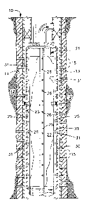
FIG. 1 is an elevational view partly in section of the alternate-path well
lS saeen having a protective shroud in accordance with the present invention: and
FIG. 2 is a cross-sectional view of the well screen of FIG. 1 taken along
line 2-2 of FIG. 1.
BEST KNOWN MODE FOR CARRYING OUT THE INVENTION
Refellin~ more particularly to the ~J~av.ings FIG. 1 illl.slfates the lower
end of a producing and/or injection well 10. Well 10 has a wellbore 11 which
e.~tends from the surface (not shown) through an uncGnsolidated and/or
fractured production and/or injection for",dtion 10. As shown wellbore 11 is
cased with casing 13 and ce",ent 14 which have pe,rorations 15 tl,erell)rough
2S to est~hlish fluid communication between fo""dtion 12 and the interior of casing
13. While well 10 is illu~l.dled as a sl~hst~rltially vertical cased well it should
be recognized that the present invention is equally usable in open-hole and/or
unde"ea,ned completions as well as in hori~ontal and/or inclined wellbores.
Aller"ate-path well screen 20 of the present invention is shown
positioned within wellbore 11 ~ cent the completion interval of formation 12
and forms an annulus 19 between the screen and the casing 13. As shown

CA 02210087 1997-07-09
F-7866
weil screen 20 is comprised of an elongated, cylindrical body 21 which includes
a permeable Uscreen'' section 22. The term Uscreen'' is used generically herein
and is meant to include and cover all types of those structures collllllollly used
by the industry in gravel pack operations which permit flow of fluids
ll,eretl,rough while blocking the flow of particulates (e.g.. co"""ercially-
available screens, slotted pipes, prepacked screens and/or liners, or
combinations thereofl. Screen 20 may be of one continuous length or it may
consist of sedions (e.g.. 30-foot sections) connected by subs or blanks as will
be understood in the art.
Allernate flowpaths (e.g.. shunts means) are mounted on the exler-,al
surface of screen 20. As shown in FIGS 1 and 2, shunt means are comprised
of at least one (four shown) perforated conduits 25 which extend longitudinally
along the external surface of screen 20. Each conduit 25 has a plurality of
openings 26 positioned along its length and is open at either or both ends to
receive gravel slurry or all conduits can be manifolded together (not shown) andfluidly connected to outlets 28 in cross-over 22 to receive gravel slurry during a
gravel pack o~erdliul ,. The construction of screen 20 to this point is basically
the same as that of known prior art alternate-path screens. Unfortunately,
however, by positioning by-pass conduits 25 on the exterior of screen 20, the
conduits are vulnerable to damage as the screen is installed into wellbore 11.
In accordance with the present invention, a protective shroud 30 is
positioned onto screen 20 over conduits 25. Shroud 30 is comprised of a
cylinder made of a strong, durable material, e.g.. steel, which is secured at its
upper and lower ends to the body of the sueen by welding or the like. The
shroud 30 has a plurality of openings 31 (only some of which are numbered in
the figures) through the wall ll ,ereof. By positioning the rigid shroud over the
conduits 26, the conduits are protected from any accidental blows or the like
during the assel,lbly and installation of the screen which might otherwise
severely damage or destroy the conduits for their intended purpose.
In operation, alternate-path screen 20 with protective shroud 30 in place
is lowered intowell bore 11 and is positioned ~5~cenlfûr,,,dlion 12. Packer29

CA 02210087 1997-07-09
F-7866
-5-
is set as will be understood in the art. Gravel slurry is then pumped down the
workstring and through outlet ports 28 in cross-over 22 into annulus 19. As the
slurry loses fluid to the formation and/or through screen 20, gravel from the
slurry is deposited in the annulus to form a gravel pack around the screen as
will be unders~ood in the art.
If excessive liquid is lost from the slurry before the annulus is filled with
gravel, a sand bridge (dotted lines 32 in FIG. 1 ) is likely to form which will block
further flow of gravel through the annulus and prevent further filling of the
annulus below the bridge. If and when this happens, the gravel slurry is still
10 free to flow through conduits 25 and out openings 26 therein and then exit
through openings 31 in shroud 30 into annulus 19 to by pass bridge 19 and
finish filling the annulus. Again, shroud 30 protects conduits 25 both during the
installation of screen 20 and the placement of the gravel pack around the
screen.

Dessin représentatif
Une figure unique qui représente un dessin illustrant l'invention.
États administratifs

2024-08-01 : Dans le cadre de la transition vers les Brevets de nouvelle génération (BNG), la base de données sur les brevets canadiens (BDBC) contient désormais un Historique d'événement plus détaillé, qui reproduit le Journal des événements de notre nouvelle solution interne.

Veuillez noter que les événements débutant par « Inactive : » se réfèrent à des événements qui ne sont plus utilisés dans notre nouvelle solution interne.

Pour une meilleure compréhension de l'état de la demande ou brevet qui figure sur cette page, la rubrique Mise en garde , et les descriptions de Brevet , Historique d'événement , Taxes périodiques et Historique des paiements devraient être consultées.

Historique d'événement

Description Date
Inactive : CIB de MCD 2006-03-12
Le délai pour l'annulation est expiré 2001-07-09
Demande non rétablie avant l'échéance 2001-07-09
Réputée abandonnée - omission de répondre à un avis sur les taxes pour le maintien en état 2000-07-10
Modification reçue - modification volontaire 1998-07-27
Modification reçue - modification volontaire 1998-06-18
Lettre envoyée 1998-03-27
Demande publiée (accessible au public) 1998-03-25
Toutes les exigences pour l'examen - jugée conforme 1997-12-04
Requête d'examen reçue 1997-12-04
Exigences pour une requête d'examen - jugée conforme 1997-12-04
Symbole de classement modifié 1997-10-09
Inactive : CIB en 1re position 1997-10-09
Inactive : CIB attribuée 1997-10-09
Modification reçue - modification volontaire 1997-09-25
Inactive : Certificat de dépôt - Sans RE (Anglais) 1997-09-22
Exigences de dépôt - jugé conforme 1997-09-22
Lettre envoyée 1997-09-22
Demande reçue - nationale ordinaire 1997-09-18

Historique d'abandonnement

Date d'abandonnement Raison Date de rétablissement
2000-07-10

Taxes périodiques

Le dernier paiement a été reçu le 1999-06-17

Avis : Si le paiement en totalité n'a pas été reçu au plus tard à la date indiquée, une taxe supplémentaire peut être imposée, soit une des taxes suivantes :

  • taxe de rétablissement ;
  • taxe pour paiement en souffrance ; ou
  • taxe additionnelle pour le renversement d'une péremption réputée.

Veuillez vous référer à la page web des taxes sur les brevets de l'OPIC pour voir tous les montants actuels des taxes.

Historique des taxes

Type de taxes Anniversaire Échéance Date payée
Enregistrement d'un document 1997-07-09
Taxe pour le dépôt - générale 1997-07-09
Requête d'examen - générale 1997-12-04
TM (demande, 2e anniv.) - générale 02 1999-07-09 1999-06-17
Titulaires au dossier

Les titulaires actuels et antérieures au dossier sont affichés en ordre alphabétique.

Titulaires actuels au dossier
MOBIL OIL CORPORATION
Titulaires antérieures au dossier
LLOYD GARNER JONES
Les propriétaires antérieurs qui ne figurent pas dans la liste des « Propriétaires au dossier » apparaîtront dans d'autres documents au dossier.
Documents

Pour visionner les fichiers sélectionnés, entrer le code reCAPTCHA :


Pour visualiser une image, cliquer sur un lien dans la colonne description du document. Pour télécharger l'image (les images), cliquer l'une ou plusieurs cases à cocher dans la première colonne et ensuite cliquer sur le bouton "Télécharger sélection en format PDF (archive Zip)" ou le bouton "Télécharger sélection (en un fichier PDF fusionné)".

Liste des documents de brevet publiés et non publiés sur la BDBC .

Si vous avez des difficultés à accéder au contenu, veuillez communiquer avec le Centre de services à la clientèle au 1-866-997-1936, ou envoyer un courriel au Centre de service à la clientèle de l'OPIC.


Description du
Document 
Date
(aaaa-mm-jj) 
Nombre de pages   Taille de l'image (Ko) 
Revendications 1997-07-09 2 55
Abrégé 1997-07-09 1 12
Description 1997-07-09 5 242
Dessins 1997-07-09 1 49
Page couverture 1998-04-01 1 51
Dessin représentatif 1998-04-01 1 20
Description 1998-06-18 5 243
Revendications 1998-06-18 2 55
Dessins 1997-09-25 1 43
Courtoisie - Certificat d'enregistrement (document(s) connexe(s)) 1997-09-22 1 118
Certificat de dépôt (anglais) 1997-09-22 1 165
Accusé de réception de la requête d'examen 1998-03-27 1 179
Rappel de taxe de maintien due 1999-03-10 1 111
Courtoisie - Lettre d'abandon (taxe de maintien en état) 2000-08-07 1 184