Note : Les descriptions sont présentées dans la langue officielle dans laquelle elles ont été soumises.
CA 02210375 1997-08-O1
MULTIPLEXER FOR MULTIPLE MEDIA STREAMS
FIELD
The present invention relates to a method and
apparatus for implementing and multiplexing multiple media
streams in accordance with IOC/AEC 13818-1 MPEG-2 systems
standard.
BACKGROUND
A multimedia system provides end-to-end service
delivery by bundling high speed multimedia streams for
transmission over ATM or other networks, unbundling them and
using or storing them. Such streams may correspond to video,
audio, signals used to control robotic applications, force-
feedback applications, agile manufacturing and the like. A
typical application may correspond to transmitting video and
audio signals over an ATM network to a desired endpoint.
The video signals may emanate as a digitized file from a file
server or be an external analog video signal as from a
camera, laser disc or VCR which must be digitized, compressed
and then sent to a network interface (NIC) card for
transmission into digital network for eventual reception by
another multimedia terminal that would perform the inverse
operation of demultiplexing, decoding and sending the decoded
video signal to an analog television monitor.
CA 02210375 1997-08-O1
2
Multimedia signals are typically high-bandwidth and
time-sensitive in nature. A suitable compression scheme is,
therefore, required such as MPEG-2 (Motion Picture Experts
Group) and involves bit-rates in excess of 4 Megabits per
second up to as high as 20 Megabits per second. One of the
problems when faced with such high bandwidth signals is how
to build an inexpensive high-bandwidth multiplexer to
packetize and synchronize multiple media streams into one
multiplex stream. One could solve the problem by using a
very expensive RISC processor to implement the transport
stream multiplexing operation but such a solution would not
be commercially acceptable.
Accordingly, it is an object of the present
invention to provide a multiplexer which uses a low cost
microcontroller and programmable logic capable of pre-
processing and parsing the bitstream before any processing by
the microcontroller.
SUMMARY OF THE INVENTION
According to the invention there is provided a
multimedia terminal having a host processor, an encoder and a
system time clock. The output of the encoder is in the form
of an elementary stream of data which is sent to a
multiplexer. The multiplexer includes a mux processor, a
FIFO and a mux logic circuit coupled to both the mux
processor and the FIFO. The FIFO is operative to buffer the
CA 02210375 1997-08-O1
3
elementary stream of data and the mux logic is operative to
preprocess the elementary stream of data in accordance with
an encoder/decoder protocol.
The encoder/decoder protocol is preferably an MPEG-
2 protocol.
The mux logic circuit monitors FIFO fullness and
signals the mux processor when there is sufficient data in
the FIFO to form the payload of a transport packet.
The mux logic circuit signals the mux processor
when a start-code is in the transport packet payload that it
is about to read.
The multiplexer includes a state of frame indicator
machine in the mux logic circuit that determines whether a
transport packet is to be treated as start of frame data. If
that is the case, the mux processor creates a transport layer
and an underlying packetized elementary stream (PES) layer.
The mux processor creates a special transport packet with an
adaptation field to contain a PES header and reads less
elementary stream data to compensate for the bytes taken up
by the PES header.
CA 02210375 1997-08-O1
4
The mux logic circuit includes a start code
tracking machine coupled to the FIFO operative to track
start-codes through the FIFO.
A presentation time stamp (PTS) generator may be
operative to latch the system time clock on access unit
boundaries and to preformat the PTS in accordance with
MPEG-2.
A program clock reference (PCR) time stamp
generator may latch the system time clock to a PCR register
once a read access is made to this register by the
multiplexer.
A presentation time stamp may be inserted into the
transport stream when the start of an encoded frame arrives
at the mux interface.
The FIFO and mux logic circuit may operate on video
elementary stream of data.
The FIFO and mux logic circuit may operate on audio
elementary stream of data.
Pre-processing and parsing of the bitstream before
arrival at the mux processor significantly reduces the number
of operations/second required of the processor.
CA 02210375 1997-08-O1
BRIEF DESCRIPTION OF THE DRAWINGS
Further features and advantages will be apparent
from the following detailed description, given by way of
5 example, of a preferred embodiment taken in conjunction with
the accompanying drawings, wherein:
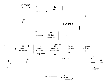
Fig. 1 is a schematic diagram of a multimedia
network coupled to a PCI Bus;
Fig. 2 is a schematic diagram of the packetizing of
a MPEG-2 video elementary stream;
Fig. 3 is a block diagram showing the multiplexer;
Fig. 4 is schematic diagram showing the functions
of both the video and audio mux logic circuits with
associated encoder and FIFO.
DETAILED DESCRIPTION WITH REFERENCE TO THE DRAWINGS
Multimedia terminals, such as multimedia desktop
computers, consist of a variety of hardware and software
modules. The hardware modules consist of physical devices
such as plug-in cards that perform specific data and signal
processing tasks, whereas the software modules comprise
microprocessor software code that executes either on
microprocessors located on the hardware modules, or on a host
CA 02210375 1997-08-O1
6
microprocessor. In the present case a set of such hardware
is shown in Figure 1 in which multimedia signals are
transmitted between an encoder 13, a decoder 17 and a network
interface device (NIC) 15 via a PCI bus 11. A host computer
27 may be coupled to the PCI bus 11 directly or through a
bridge 29 from another PCI bus 31. For example, analog video
signals are received by an NTSC decoder 21 which digitizes
the analog input to provide a digital stream for the frame
buffer 19. The frame buffer 19 synchronizes digital video
data to the system time clock (STC) 25. The program clock
reference (PCR) 23 is a MPEG-2 preformatted packet obtained
from a PCR register to which the STC 25 is latched once the
mux 30 has read from this register. It is a time stamp that
synchronizes the sending and receiving terminals and is
generated at intervals specified by the host software just
prior to being read by the NIC 15. It is multiplexed
together with audio and video data and sent to the NIC 15 in
packets in priority ahead of the audio and video data. At
the receiving terminal (not shown) the transport stream is
demultiplexed so that separate audio, video and PCR streams
are reproduced.
Referring to Fig. 2 each video frame has a start
code (SC) at the beginning of the frame followed by other
header information. The MPEG video elementary stream is
formed into a packetized elementary stream which includes a
Packetized Elementary Stream header (PES Header) containing
CA 02210375 2001-O1-24
CA9-97-'025 '7
Presentation Time Stamp (PTS) information. The PES Header is
inserted every n access units where an access unit is a frame of
compressed video or audio data. The PTS contains the time at
which the audio or video frame is encoded. In
addition, each video or audio frame including its start code
is concatenated after the PES Header. From the packetized
elementary stream an MPEG-2 Transport stream is formed by
breaking up separate PES streams into transport packet
l.0 payloads. Transport packet header information is generated
(4 bytes) appended to 184 bytes of payload data packets
containing either audio or video data are built depending
upon which data is ready for insertion first. This process
is continued until a start code for either audio or video
frames is encountered at which point a new PES packet is
started.
The MPEG-2 Encoder 12 delivers an MPEG-2 video
elementary stream to the video mux logic 16 and the audio
2:0 encoder 14 generates an elementary stream which it sends to
the audio mux logic circuit 18. The mux logic circuits 16
and 18 associated with FIFO's 32 (see Figure 4) which
buffer the video and audio elementary stream data and, when
there is sufficient video data in the FIFO 32 (see Figure 4)
to form the payload of an MPEG-2 transport packet, signals
a mux microprocessor 22. A Video Fullness Counter 40 (see
Figure 4) then keep track of the number of bytes of video
data in the FIFO 32 at any time. An interrupt generator 42
CA 02210375 1997-08-O1
g
interrupts the mux 30 whenever the number of bytes in the
video FIFO 32 exceeds 184.
As further seen in Figure 4, compressed data from
the encoder 12 is directed both to a FIFO 32 and to the mux
logic circuitry 16. The mux processor 22 is alerted when
there is a video start-code in the transport packet payload
that it is about to read. This allows the mux processor 22
to create the transport layer at the same time it is creating
the underlying PES layer. If the mux 30 is aware that an
access unit starts in the next transport packet payload it
can create a special transport packet with an adaptation
field to contain the PES packet header. The mux 30 will also
realize that as a result of the PES header, the transport
packet payload will be smaller and it will subsequently read
less elementary stream data from the FIFO 32.
Preprocessing such as this allows the mux processor
22 to simultaneously do PES and transport layer packetization
without using extra instruction cycles transferring data to
temporary storage. As data is read into the compressed data
FIFO 32 scanning for start codes by a video start code detect
state machine 44 is carried out to determine when a video
start-code is in the next TS (time stamp) payload. The start
code detect state machine 44 detects start codes on byte
boundaries. Then a start code is detected, the value in the
FIFO-fullness-counter 40 is latched into another counter
CA 02210375 1997-08-O1
9
called the start-code position counter 48. The start-code
position counter 48 only counts down on compressed data FIFO
reads by the mux 30. Preprocessing such as this removes
instruction cycle intensive tasks such as start-code scanning
from the microprocessor 22. Interrupt generation logic
consists of comparators (not shown) which compare the values
of the two counters, namely, the FIFO fullness counter 40 and
the start-code position counter 48 with the threshold value
of 184 bytes.
Data entry into the FIFO 32 is controlled by FIFO
write logic 41 in the mux logic circuits 16 and 18.
Integrating the FIFO write logic 41, start-code detect state
machine 44, FIFO-fullness counter 40 within the same logic
block allows these three systems to exchange information
easily.
The audio mux logic circuit 18 performs similar
functions to the video mux logic circuit 16. It buffers the
audio elementary stream data, signals the mux processor 22
when there is sufficient audio data in the FIFO to form the
payload of a MPEG-2 transport packet and signals the mux
processor 22 when the data in the current payload contains an
audio start-of-frame. Audio logic is implemented in exactly
the same way as the video logic and is implemented in the
same logic block.
CA 02210375 1997-08-O1
The clock logic 20 maintains a 27 MHz system time
clock as per the MPEG-2 standard. It also generates video
and audio presentation time stamps (PTS) by latching the
system time clock (STC) on access unit boundaries. The mux
5 processor 22 is interrupted when a new PTS is available. The
PTS is made available to the mux processor 22 and is pre-
formatted as per the MPEG-2 standard so that the mux 30
doesn't need to expend effort on bit-shifting operations.
The clock logic 20 also generates program clock reference
10 (PCR) time-stamps. The STC is latched to the PCR register
once the mux 30 reads from this register. The PCR is pre-
formatted as per the MPEG-2 standard so that the mux 30
doesn't need to expend effort on bit-shifting operations.
Treatment of the data by the mux processor 22
involves processing of the video elementary stream. The
video processing algorithm in the mux processor 22 packetizes
the video elementary streams by adding PES headers and time
stamps as specified by the host 27. The packetized
elementary stream is then segmented into transport packets
and inserted into the payload data unit (PDU) queue.
Every time the video mux logic 16 buffers enough
data to create a transport packet (184 bytes), the mux
processor 22 is signaled. The mux processor 22 processes the
data in one of two ways: the first method is to treat the
data as ordinary payload data, and the other is to treat it
CA 02210375 1997-08-O1
11
as start-of-frame (SOF) data. The method of treatment is
determined by whether a start-of-frame (SOF) indicator (not
shown) is set by the video mux logic 16.
Ordinary data is simply encapsulated with transport
packet headers and queued into the PDU queue. However,
start-of-frame data is counted and the count is used to
determine whether a presentation time stamp is inserted. The
presentation time stamp is captured by the mux processor 22
when it is signaled by the video mux logic block that a frame
is being encoded. The interval at which the PTS must be
inserted is determined by the host 27, but it cannot exceed
700 milliseconds. Since the video frames are fixed
intervals, a count of the start-of-frame can be used to
determine when to insert the PTS.
Rate control may be necessary when the channel
bandwidth is exceeded by the elementary stream video data and
the data is backed up into the video FIFO 32.
The basic algorithm is:
if there is enough data to form a transport packet PDU
if it contains an video SOF
count and compare the number of video SOF since last PES header if
number of SOF counted indicate time to insert PTS
CA 02210375 1997-08-O1
12
read PTS and add offset
create and insert the PES headers
encapsulate the PES header and data with the transport packet header
S insert into the PDU queue
else
encapsulate the data with the transport packet header insert into the
PDU queue
The audio processing section packetizes the audio
elementary streams by adding PES headers and time stamps as
specified by the host 27. The packetized elementary stream
is then segmented into transport packets and inserted into
the PDU queue.
Every time the audio mux logic buffers enough data
to create a transport packet (184 bytes), the mux processor
22 is signaled. The mux processor 22 processes the data in
one of two ways: the first method is to treat the data as
ordinary payload data, and the other is to treat it as a
start-of-frame (SOF) data. The method of treatment is
CA 02210375 1997-08-O1
13
determined by whether the start-of-frame indicator is set by
the audio mux logic 18.
Ordinary data is simply encapsulated with transport
packet headers and queued into the PDU queue. However,
start-of-frame data is counted and the count is used to
determine whether a presentation time stamp is inserted. The
presentation time stamp is captured by the mux processor 22
when it is signaled by the audio mux logic block that a frame
is being encoded. The interval at which the PTS must be
inserted is determined by the host, but it cannot exceed 700
milliseconds. Since the audio frames are fixed intervals, a
count of the start-of-frame can be used to determine when to
insert the PTS.
The basic algorithm is:
if there is room in the PDU queue
if there is enough data for a transport packet
if it contains an audio SOF
count and compare the number of audio SOF since last PES
header
if number of SOF counted indicate time to insert PTS
CA 02210375 1997-08-O1
14
read PTS and add offset
create and insert the PES headers
encapsulate the PES header and data with the
transport packet header
insert into the PDU queue
else
encapsulate the data with the transport packet header
insert into the PDU queue
The PCR program clock reference packet is generated
at intervals specified by the host software. Due to the
sensitive nature of the time reference to fitter, the actual
reference value is only captured just prior to being read by
the NIC 15 to avoid any buffering delay. This block serves
to set a flag to indicate that such PDU is to be generated by
the NIC interface section.
The basic algorithm used here is
if PCR generation interval has expired
CA 02210375 1997-08-O1
set flag to indicate that a PCR PDU is to be generated and sent to the
NIC
else
5
if there are enough transport packets in the PDU queue to
form a PDU
(
initiate transfer to the NIC
10 )
Accordingly, while this invention has been
15 described with reference to illustrative embodiments, this
description is not intended to be construed in a limiting
sense. Various modifications of the illustrative
embodiments, as well as other embodiments of the invention,
will be apparent to persons skilled in the art upon reference
to this description. It is therefore contemplated that the
appended claims will cover any such modifications or
embodiments as fall within the true scope of the invention.