Note : Les descriptions sont présentées dans la langue officielle dans laquelle elles ont été soumises.
CA 02211221 1997-07-22
BRITA Wasser-Filter-Systeme GmbH
Heinrich-Hertz-StraBe 4, 65232 T~llnn~stein
Filter means with fabric insert
10 The invention relates to a filter means for liquids with a filter cup filled with filter
material, the base of which has at least one sieve-like outlet aperture for the liquid,
and with a lid which is provided with at least one sieve-like inlet aperture for the
liquid and is joined in a liquid-tight manner to the filter cup.
15 Numerous filter means of the type described hereinabove are known, for example
for filtering water, wherein ion exchangers and/or activated charcoal are used as
filter material. The known filter means has the form of a cartridge, the centrallongitll~in~l axis of which is preferably vertically arranged such that the lid is at the
top and the base of the filter cup is located at the bottom, and the liquid, preferably
20 the water to be filtered, flows into the lid at the top and leaves the filter cup below
at the base. The known filter means is inserted in a funnel provided for it in awater purification device, which is placed on a receiving or collecting container for
filtered liquid, and preferably is closed at the top with a removable lid. Into the
funnel at the top, the user places, for example, tap water, which can be used for
25 prepaling tea or the like after passing through the filter means into the collecting
coll~aill~r.
Filter cups and lids are known which have narrow slits forming the inlet and outlet
apertures, as these are easy to m~mlf~ lre using injection moulding techniques.
30 Injection mouldable plastics is preferably used for such filter means.
CA 02211221 1997-07-22
It is desirable for as effective filtering as possible to provide the liquid entering the
filter means with as large a surface of filter material as possible, and to force the
liquid to undergo as intensive and comprehensive an adsorption procedure as
possible. It is known that when gr~nul~t~s are used as filter material, the smaller the
5 size of the individual filter particles, the greater the active surface. It may happen
that particles of approximately 200 ~m and smaller are present in the filter material.
The active surface available to the liquid to be filtered passing through is thus
satisfactorily large. With this advantage also comes the disadvantage, however, that
some of these smallest granulate particles pass through the imet aperture in the lid
10 and the outlet opening in the base. The particles, for example black activated
charcoal particles, some floating on the surface of the liquid, bother the user and are
undesirable.
The m~mlf~ lrer of such filter means has naturally attempted to reduce the size of
15 the inlet and outlet ape.lules. With the slit shape for these apertures, which is
easily achieved by injection moulding, there has been no success, in a reproducible
and controlled manner, in making the width of the slits less than 200 ~m with
precision. In particular, activated charcoal particles can be plate-shaped, their
mil,i",ll~" dimension re~rhing 250 ~m or less, so it is precisely these particles,
20 which are easily optically visible to the end-user, which can pass through the inlet
and outlet slits already representing the lower limit for injection moulding
technology.
Planar sieve fabrics in the form of fibrous webs are already placed now on the inner
25 surface of the base of a filter cup and in t'nis way prevent the passing out of smaller
particles. Disadvantageously, however, germs collect on such fibrous webs and
sieve fabrics made, for example, from paper pulp.
There are also plastics injection moulded sieve fabrics with a smaller pore size of,
30 for example, 200 ~m, which have been experimentally been arranged on the top and
bottom of the filter cup to try to hold back the filter material. With this, there have
CA 02211221 1997-07-22
up until now been difficulties, to an inexplicable degree, with the through-flow of
the liquid with this type of sieve.
The object of the invention is to provide improvements and measures to the extent
5 that even small particles of granulate of, for example, < 200 ~m wide cannot pass
through the apertures in the lid, while m~int~ining perfect functioning of the filter
means described in the introduction.
For reasons of filling technology and operational technology, the known filter cup
10 is filled with filter material to only approximately 85 % to 95% of its total interIlal
volume, and subsequently the lid is fitted and fixed in a liquid-tight manner onto
the top edge of the filter cup.
When the te~clling of the present invention is considered, however, in accordance
15 with which the object described above is solved, in that a fabric insert is arranged
between the filter cup and the lid, which has at least one fabric piece projecting into
the filter cup, the ret~ining ability is .si~nifiL~ntly improved and a good through-flow
lS ensured.
20 A plane can be im~gin.od, lying across the top edge of the cup, in particular the
filter cup considered here, along which the lid is sealed to the filter cup in a liquid-
tight manner. If a planar fabric insert is to be arranged between the filter cup and
the lid, approximately in the area of this im~gin~ry plane, there would then be flow
problems with the liquid to be filtered. It is evident that above the lid immersed in
25 the liquid to be filtered there is not a very high column of water so the pre~uie of
the liquid caused by gravity is not very great. Additionally, it is known that a liquid
has surface tension, which particularly in the case of small sieve pores has a
negative effect to the extent that the slightest back ~les~ule of air under the lid is
sufficient to block the through-flow of the liquid. The use of a planar fabric insert
30 could not alleviate such a defect.
CA 02211221 1997-07-22
In accordance with the invention, a fabric insert is now proposed which has at least
one fabric piece, that is to say an area of its sieve fabric, which projects from the
plane described into the filter cup, that is to say in the direction of the filter
material. When the filter cup is filled with filter material almost "up to the top",
5 that is to say to up to 85 % or to 95 %, this projecting fabric piece of the new fabric
insert according to the invention is in contact with the filter material, and in this
way, at this point hlte~ Ls the surface tension, with the result that the liquid begins
to flow here, any air cushion under the lid is squeezed out and thereby any backpressure counter to the pl~s~ule of the column of liquid significantly reduces and
10 finally clears. The liquid to be filtered can flow through the filter material without
any problem and the small particles of the filter material are at the same time held
back extremely well.
It is particularly advantageous according to the invention when the projecting fabric
15 piece is partially dome-shaped. It is known to m~mlf~tnre fabric pieces with a
structure approximately like that of a gauze, except that in the case of the invention
the fabric is advantageously made from plastics. Clearly, even when the plasticsis non-woven, the word "fabric" can be used for this net-like sieve construction.
Thin plastics threads cross at right angles or at an angle and in this way make pores
20 of a size which could not be made smaller in the case of the slits using injection
moulding techniques.
As with a gauze, the fabric piece made from plastics can also be made with different
surface shapes. Dome-shaped is understood to be any curvature of the surface, so25 that coffee filter shaped fabric pieces, trunr~t~ cone-shaped fabric pieces or the like
can be envisaged.
It is particularly pl~fe.led when, according to the invention, the fabric piece has the
shape of a segment of a sphere and is fixed to a ret,.ining ring. The segment of a
30 sphere is produced in a known manner by the intersection of a sphere along one
plane. This plane intersects the sphere along a small circle, producing the sphere
CA 02211221 1997-07-22
cap, which can also be described as the sphere top or calotte. The retaining ring
then lies along the small circle of this top or cap-like fabric piece. The ret~ining
ring lies in a plane from which the sphere cap shaped fabric piece projects towards
the filter material.
In particular, from a m~nl1f~ ring point of view, it is advantageous when
according to a further configuration of the invention, the fabric piece is fixed onto
ribs. The ribs are preferably made from the same plastics as the other parts (cup,
sieve lid and so forth) or a compatible material so that the sieve fabric can be10 injected between the ribs. The ribs can follow the domed or otherwise configured
shape of the fabric part projecting into the filter cup and stabilise this shape. This
is particularly advantageous with filter cups filled to the maximum extent with filter
material, in which after filling a kind of cone of material with a raised area stands
up in the centre such that the sphere cap shaped fabric piece, when placed on the
15 free top edge of the filter cup, experiences a certain p.es~ule force which could
deform a very fine fabric piece. The shape ret~ining ribs resist this small ples~u.e
force and keep the projecting fabric piece very precisely in shape.
In a further advantageous configuration of the invention, the fabric part projecting
20 furthest into the filter cup is surrounded by an annular rib. The contact between the
projecting fabric piece on the one hand and the filter material filled in on the other
hand is often best effected when it is not a rib, but instead the fabric piece itself
which comes into contact with the filter material, as the liquid is in contact with the
fabric piece itself and its surface tension will be inte~ pted. In automatic filling
25 in~t~ tions for filter cups, a kind of cone of material forms from time to time, the
part of which that stands up furthest is located approximately in the centre. If, in
the example prese~lly being considered, a sphere cap shaped fabric piece is used,
the point projecting down furthest, like the pole of this sphere cap, is the first to
come into contact with the filter material. The annular rib described here ensures
30 that the fabric piece projecting furthest is the first to come into contact with the
filter material and not, for example, a rib. In this way reliable illtell,l~tion of the
CA 02211221 1997-07-22
surface tension is provided so that blockage of the flowing liquid during operation
of the filter means according to the invention no longer occurs.
I~ is advantageous when, according to the invention, the pore size of the fabric is
in the range of 50 ~m to 300 ~m, and preferably of 80 ~m to 200 ~Lm. The filter
means according to the invention can be operated without any through flow
problems, when the pore sizes lie within the range described, and then very
effective filter materials can also be used with large active surfaces (small particles),
without the risk of small particles trickling out or floating through the apertures.
It can be advantageous from a m~mlf~ ring point of view to join the lid to the
fabric insert in a non-removable manner. The injection moulding m~nllf~chlrer can,
for example, mould the lid, inject the fabric insert, and join these two parts
together, for example by welding. This intermediate product can then be delivered
15 to the filling plant where is available in m~g~7.in~s and is taken hold of by an
automatic closing m~chin.o, in order to then be placed on the filled filter cup and
joined thereto. Neither a m~chin~, nor the m~mlf~clllrer's staff have then to bother
with individual fabric inserts and transport and arrange them with particular care.
The lid must nevertheless be correctly positioned to close the filter insert, and when
20 the fabric insert is joined to it in a non-removable manner, no special assembly step
is additionally n~cec~
The use of a hydrophilised plastics fabric in a filter means of the type described
hereinabove is also advantageous. In order to improve, that is to say to shorten,
25 the through flow time of the liquid to be filtered, it is advantageous to treat the sieve
fabric made from plastics with s~lb~l~n~es by means of which the fabric becomes
hydrophillic. These substances can be liquids which affect the surface of the
plastics.
30 in a similar manner, in accordance with the invention a bacteriostatically treated
plastics fabric can be used in the filter means described hereinabove. There are
CA 02211221 1997-07-22
different methods for this, among which are the effects of steam, irradiation and the
like.
Further advantages, features and possibilities for application of the present invention
5 will be evident from the following description of a p,efclled embodiment with
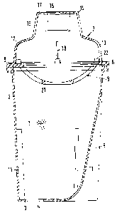
reference to the attached drawings. In these is shown, in
Figure l a cross-section view through the filter means according to the invention,
Figure 2 a plan view of the fabric insert from the side of the filter cup, and
10 Figure 3 a cross-section view through the lid with the fabric insert fitted onto it.
The filter means according to a prerclled embodiment, shown completely in cross-section in Figure 1, is composed of a lower part being a filter cup 2 with granular
filter material l, the base 3 of which has outlet apertures 4 with sieve means which
15 are not shown and at one point is drawn up inwards at an angle, forming a
ventilation notch 5. The side walls of the filter cup 2 ~e~ t~ at the top in a
sealing flange 6 which encloses an im~gin~ry horizontal plane; the filter means is
further composed of the lid, generally labelled 7, the outer, lower flange 8 of which
tennin~t~s in the same im~gin~ry horizontal plane and is inserted in the sealing20 flange fitting such that a liquid-tight join, for example a weld, is easily possible.
In addition to the filter cup 2 and the lid 7 placed on it, in the embodiment shown
here, the filter means has as its third part a fabric insert 9 which has a ret~ining ring
10 which also ~,lr,oll~,ds the im~in~ry horizontal plane. In this way the ret~inin~
ring 10 of the fabric insert 9 fits the lid 7 and the filter cup 2 in such a way that in
25 the area of the common joining plane the three parts can be joined to one another
in a liquid tight manner, for example by welding.
In addition, st~l~king ribs 11 can be seen in the filter cup, which extend from the
base 3 upwards over approximately half the height of the filter cup 2 and are
30 regularly distributed, angled towards the inside, on the side walls, for example in
threes. After st~rking one inside another, the finished filter cups 2 are set down on
CA 02211221 1997-07-22
these stacking ribs 11 for storage. Before assembly of the filter means, the empty
filter cups 2 can therefore be stored in rod-like stacks in a m,.g~ine.
The lid 7 is composed of a lower outer part 12 adjacent to the external flange 8, in
5 the surface of which inlet apertures 13 for the liquid to be filtered are arranged in
a ring. The respective vertical section through the lid 7 according to Figures 1 and
3 is set out such that on the right-hand side it runs straight through an inlet aperture
13.
10 This outer part 12 of the lid 7 narrows towards the top and te.~nin~tes in a gripping
part 14 with an in~ent~tion 15 for gripping and with ventilation slits 16 as well as
some ventilation holes 17 arranged above them, through which air rising up from
below during operation can disperse outside the filter means. Finally, on the inner
surface of the lid 7 ret~ining ribs 18 can be seen, by means of which a contact
15 surface with the fabric insert 9 is produced in the lid 7.
The fabric insert 9, mainly visible in the centre, viewed from below in the direction
of the arrow A in Figure 3, is composed of a sphere cap shaped fabric piece 19
which is indicated by inclined h~trhing, and should be thought of as having a gauze-
20 like structure. The whole hatched surface of the sieve fabric is represented by thedomed fabric piece 19 projecting in the direction of the filter material 1, which is
injection moulded into the planar ret~ining ring 10. Ribs 20 with the centrally
arranged annular rib 21 are also injected onto the fabric piece 19 and keep it in a
stable shape as a sphere cap.
On the side facing away from the dome-shape facing downwards towards the filter
cup 2, that is to say the side facing upwards in Figures 1 and 3, which also show
the ope.dL~g shape, four positioning knobs 22 are fitted on the ret~ining ring 10
evenly distributed about the periphery, which project upwards such that they
30 coincide with the contact surface of the four ret~ining ribs 18 in the lid 7, when the
ret~ining ring 10 is located in the correct position. This is shown in the Figures.
CA 02211221 1997-07-22
After completion of the filter cup 2, the lid 7 and the fabric insert 9, the fabric
insert can be fitted in the position shown in Figure 3, in which the positioning knobs
2 are brought into contact with the ret~ining ribs 18 and the ret~inin~ ring 10 is
located in the peripheral flange 8 of the lid 7. In this arrangement the fabric insert
5 9 is welded in a liquid-tight manner to the lid 7.
The filter cup 2 is filled with filter material 1, whereafter the lid 7 is brought into
the position shown in Figure 1 and the flange 8 is welded liquid-tight onto the
sealing flange 6.
The filter means made in this way according to Figure 1 can then be placed in a
filter device and used by the end user. The liquid poured in at the top, preferably
water to be filtered, enters through the liquid inlet apertures 13, also described as
sieve slits, in the lid 7, flows through the fabric insert 9, the filter material 1, and
15 leaves the filter cup 2 through the outlet aperture 4 which keeps the filter material
1 back by means of a sieve.