Note : Les descriptions sont présentées dans la langue officielle dans laquelle elles ont été soumises.
CA 02211607 2002-04-11
:o,.°~.
BACKGROUND OF THE INVENTION
1. Field of the Invention. The subject invention is ,
directed to exhaust mufflers manufactured substantially from formed
components, such as stamp formed sheets of metal.
2. Description of the Prior Art. The typical prior art
exhaust muffler includes a plurality o~f separate parallel tubes
that are supported by transversely extending baffles. The baffles
typically are of oval or circular shape. The~assembly of tubes and
baffles is slid into a tubular shell having a shape conforming to
the shape of the baffles. An outer wrapper may be wrapped around
the shell for additional strength and for noise insulation.
Opposed end caps are then mechanically connected to the ends of the
shell and wrapper to enclose the muffler. The end caps include
apertures to define an inlet and an outlet on the muf f ler . The
most common prior art mufflers include a single inlet in one. end
cap of the muffler and a single outlet in the opposed end cap.
However, other configurations of inlets and outlets are possible
and are used: periodically to accommodate the particular needs o~ an
exhaust system.
Chambers are formed within the above described prior art
muffler between adjacent baffles or between a baffle and ari end
cap. Selected tubes within the muffler may be perforated or
louvered to permit a controlled expansion of exhaust gas into the
surrounding chamber. Other tubes may have their end in a
1
CA 02211607 1997-07-28
particular chamber so that all gas flowing through that tube will
empty into the associated chamber. The particular dimensions of
the tubes, chambers and apertures or louvers will be selected to
efficiently attenuate the noise associated with the exhaust gas
flowing from the engine.
The primary flow of exhaust gas in the above described
prior art muffler is generally parallel to the axis of the tubular
outer shell. However the flowing exhaust gas will periodically
reverse directions in chambers formed adjacent the end caps. A
secondary flow of exhaust gas may occur as the exhaust gas expands
through the perforations or louvers in a tube and into surrounding
chambers. Prior art mufflers with tubular outer shells generally
have not included chamber walls that extend parallel to the axis of
the outer shell.
The prior art mufflers described above generally perform
very well. However, these mufflers include a large number of
separate parts that must be assembled in a labor intensive
manufacturing process. Additionally, these prior art mufflers are
limited to substantially tubular shapes with few options for
location and alignment of the inlet and outlet of the muffler.
The prior art also includes mufflers made substantially
from a plurality of formed sheets of metal. The typical prior art
stamp formed muffler includes a pair of internal plates that are
formed with channels. The internal plates are secured in face-to-
face relationship such that oppositely directed channels
substantially register with one another and define tubes for
2
CA 02211607 1997-07-28
accommodating the flowing exhaust gas. Portions of these stamp
formed tubes may be perforated or louvered to permit an expansion
of exhaust gas therefrom. The typical prior art stamp formed
muffler further includes a pair of outer shells. Each outer shell
is stamped to define a generally planar peripheral flange. At
least one chamber extends from the plane of the peripheral flange.
The peripheral flanges of these outer shells are secured to
peripheral regions of the internal plates such that the chambers
surround the array of tubes defined by the internal plates.
Typically each tube of the prior art stamp formed muf f ler
will communicate simultaneously with the chambers on opposite sides
of the respective internal plates. However, an exception is U.S.
Patent No. 4,765,427 which has first and second internal plates
formed to define first and second substantially parallel tuning
tubes. A first external shell defines a first low frequency
resonating chamber surrounding the first internal plate, while a
second external shell defines a second low frequency resonating
chamber surrounding the second internal plate. Portions of the
first plate that define a first tuning tube include an opening to
permit the first tuning tube to communicate with the first low
frequency resonating chamber. However, portions of the second
tuning tube defined by the first internal plate have no opening.
Hence the second tuning tube does not communicate with the first
low frequency resonating chamber. Portions of the second internal
plate defining the second tuning tube have an opening to permit the
second tuning tube to communicate with the second low frequency
3
CA 02211607 1997-07-28
resonating chamber. However, portions of the second internal plate
defining the first tuning tube have no opening. Thus, if the
internal plates are aligned horizontally, the first tuning tube may
communicate with a top low frequency resonating chamber, while the
second tuning tube may communicate with a bottom low frequency
resonating chamber. Flow patterns of this type generally were not
possible with the prior art conventional muffler with a wrapped
outer shell. U.S. Patent No. 5,004,069 shows a somewhat similar
concept applied to expansion chambers.
Exhaust mufflers typically create a back pressure on the
flowing exhaust gas. Back pressure retards engine performance, and
hence an exhaust muffler should be designed to achieve its noise
attenuating function without an unacceptably high back pressure.
Stamp formed mufflers generally permit curved surfaces that are not
possible with conventional mufflers employing standard tubes and
wrapped outer shells. Curved surfaces reduce back pressure and
improve engine performance. Back pressure may be further decreased
by utilizing the maximum volume available for the flowing exhaust
gas. In this regard, a large tube or large chamber is generally
less restrictive than a smaller tube or smaller chamber for
accommodating a flowing exhaust gas. A stamp formed muffler with
effective use of curved surfaces to reduce back pressure is shown,
for example, in U.S. Patent No. 5,252,788. A stamp formed muffler
that relies largely upon a plurality of in-line flow chambers in an
effort to avoid high back pressure is shown in U.S. Patent No.
5,173,577. In this latter muffler, each of the in-line flow
4
CA 02211607 1997-07-28
chambers is disposed between the internal plates of the muffler.
Certain of these in-line flow chambers or in-line flow tubes may be
perforated to permit expansion of exhaust gas into surrounding
chambers defined by the external shells. However, these chambers
defined by the external shells are not part of the primary flow
path of exhaust gas moving from the inlet to the outlet of the
muffler.
The hot flowing exhaust gas typically includes caustic
vapors. These vapors will condense when the engine is shut off and
the muffler is permitted to cool. The caustic condensate will
accumulate at the gravitational low point of the muffler, and may
corrode the metal from which the muffler is formed. Various
attempts have been made to prevent muffler corrosion. For example,
some mufflers simply provide a drainage hole at the gravitational
low point. However, the drainage hole can become clogged.
Furthermore, some new car manufacturers will not permit drainage
holes . Other muf f lers provide a s iphon tube extending from the
gravitational low point to the outlet tube of the muffler.
Pressure differentials between the gravitational low point in the
chamber and the outlet tube will cause the flowing exhaust gas to
effectively suck liquid from the gravitational low point. The
incorporation of a separate siphon tube into a conventional muf f ler
requires complex welding and additional costs. A stamp formed
muf f ler with a separate s iphon tube is shown in U . S . Patent No .
5,563,385. A stamp formed muffler with a stamp formed siphon tube
is shown in U.S. Patent No. 5,563,383.
CA 02211607 1997-07-28
In view of the above, it is an object of the subject
invention to provide a muffler manufactured substantially from
stamped components with an enhanced ability to attenuate noise
while maintaining a desirably low back pressure.
It is a further object of the subject invention to
provide a stamp formed muffler with large flow paths and in-line
flow chamber for the exhaust gas.
A further object of the subject invention is to provide
a muffler having a plurality of in-line flow chambers separated
from one another by internal plates of the muffler.
Still a further object of the subject invention is to
provide a muffler that can effectively siphon exhaust gas from the
gravitational low point of the muffler without providing separate
siphon tubes.
6
CA 02211607 1997-07-28
SUMMARY OF THE INVENTION
The subject invention is directed to an exhaust muffler
manufactured from a plurality of sheets of material. The
respective sheets are formed to define a plurality of exhaust
passages and chambers as described herein. The formation of the
sheets preferably is carried out by stamping. However, other known
metal formation techniques may be employed, such as forming
techniques that rely upon hydraulic forces, magnetic forces and/or
explosive forces.
The muffler comprises at least one internal plate formed
to include a peripheral flange and a channel. Portions of the
internal plate between the peripheral flange and the channel may
include a plurality of louvers, perforations or other known opening
means for accommodating a flow of exhaust gas. The internal plate
may be a first internal plate, and the muffler may further include
a second internal plate. The second internal plate may have a
peripheral flange substantially registerable with the peripheral
flange of the first internal plate and may further include an array
of louvers, perforations or other opening regions disposed inwardly
from the periphery. Portions of the internal plates spaced
inwardly from the registered peripheral flanges may be formed to
define an internal chamber therebetween.
The muffler further includes an inlet tube plate formed
to define a channel flanges dimensioned and configured for
engagement with portions of the internal plate or the first
internal plate on opposite respective sides of the channel formed
7
CA 02211607 1997-07-28
therein. Thus, the channel in the internal plate and the channel
in the inlet tube plate function as an inlet tube for channeling
exhaust gas into the muffler. Portions of the inlet tube may be
provided with a plurality of louvers, perforations or other known
opening means for permitting expansion of exhaust gas. Preferably
the louvers in the inlet tube are formed in either the internal
plate or the tube plate, but not in both. Thus, exhaust gas flow
will be permitted from only one side of the inlet tube. Preferably
the louvers are formed through a side of the inlet tube facing the
gravitational top of the muffler.
The muffler further includes first and second external
shells. Each external shell is formed to define a chamber and a
peripheral flange surrounding the chamber. Peripheral flanges of
the first and second external shells are dimensioned and configured
to register with one another and to register with the peripheral
flange of the internal plate. The peripheral flanges of the
external shells are secured to the peripheral flange of the
internal plate so that chambers defined by the external shells
surround the perforations or louvers in the internal plate. The
peripheral flange of the second external shell may be secured to
the peripheral flange of the second internal plate on embodiments
of the muffler having both first and second internal plates.
The second external shell preferably defines the
gravitational bottom external shell. Thus, any condensate
accumulating in the muffler will accumulate on the inwardly facing
surface of the second external shell.
8
CA 02211607 1997-07-28
The muffler further includes at least one outlet tube
extending from the chamber defined by the second external shell to
an outlet of the muffler. The outlet tube may be a conventional
separate tube extending from the chamber defined by the second
external shell to an external region . The conventional tube may be
bent to lie in substantially abutting relationship with the
inwardly facing surface of the second external shell. Thus, the
outlet tube will effectively siphon any condensate lying on the
inwardly facing surface of the second external shell and remove the
condensate from the muffler. The outlet tube may also be defined
by an outlet tube plate. The outlet tube plate may be structurally
similar to the inlet tube plate. In particular, the outlet tube
plate may be formed to include a channel and flanges. The tube
plate flanges may be secured to either an internal plate or the
second external shell, and may extend to the outlet from the
muffler. If the tube plate is secured to an internal plate of the
muffler, it is preferred that the tube plate be dimensioned to
extend into abutting contact with the second external shell to
enable the outlet tube formed by the tube plate to effectively
siphon condensate accumulated on the inwardly facing surface of the
second external shell.
Exhaust gas enters the muffler of the subject invention
by flowing through the inlet tube formed by the inlet tube plate
and the internal plate. The exhaust gas then will flow through the
perforations in the inlet tube and into the chamber defined between
the internal plate and the first external shell. Exhaust gas will
9
CA 02211607 1997-07-28
exit the chamber def fined by the f first external shell by f lowing
through the perforations in the internal plate. Embodiments of the
muf f ler having f first and second internal plates will permit f low of
exhaust gas into the internal chamber defined between first and
second internal plates. In this embodiment, the second internal
plate will also include louvers or perforations to permit exhaust
gas to exit into the chamber defined by the second external shell.
Exhaust gas will then flow through the outlet tube and from the
muffler. The outlet tube is positioned to permit flowing exhaust
gas to siphon condensate from the gravitational low points of the
muf f ler .
CA 02211607 1997-07-28
BRIEF DESCRIPTION OF THE DRAWINGS
FIG. 1 is a perspective view of a muffler in accordance
with the subject invention.
FIG. 2 is a top plan view of the assembled muffler of
FIG. 1.
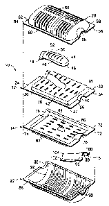
FIG. 3 is an exploded perspective view of the muffler of
FIGS. 1 and 2.
FIG. 4 is a cross-sectional view taken along line 4-4 in
FIG. 2.
FIG. 5 is a cross-sectional view taken along line 5-5 in
FIG. 4.
11
CA 02211607 1997-07-28
DETAILED DESCRIPTION OF THE PREFERRED EMBODIMENT
A muffler in accordance with the subject invention is
identified generally by the numeral 10 in FIGS. 1-4. The muffler
includes upper and lower internal plates 12 and 14, upper and
lower tube plates 16 and 18 and upper and lower external shells 20
and 22.
The upper internal plate 12 is generally rectangular as
depicted herein, and includes an inlet end 24, an outlet end 26 and
opposed longitudinal sides 28 and 30. However, many non-
rectangular shapes may be provided in accordance with the available
space on the vehicle. Additionally, the inlet and outlet of the
muffler need not be at opposed ends or sides.
The upper internal plate 12 includes a top sur face 32 and
a bottom surface 34. A generally planar peripheral flange 36
extends substantially around the upper internal plate 12. Portions
of the upper internal plate 12 thin the area bounded by the
peripheral flange 36 defines a chamber 37 that is formed such that
the upper surface 32 is generally convex and the lower surface 34
is generally concave. The upper internal plate 12 is further
characterized by an inlet channel 38 extending from the inlet end
24 to a location intermediate the opposed inlet and outlet ends 24
and 26. As shown herein, the inlet channel 38 extends downwardly,
and therefore is a concave portion of the upper surface 30 of the
upper internal plate 12. Additionally, as shown herein, the inlet
channel 38 is substantially free of perforations or louvers. The
upper internal plate 12 further includes a short outlet channel 40
12
CA 02211607 1997-07-28
extending to the outlet end 26 of the upper internal plate 12. The
outlet channel 40 extends upwardly, and hence defines a convex
portion of the upper internal plate 12. Portions of the upper
internal plate 12 spaced from the inlet and outlet channels 38 and
40 and within the area defining the chamber 37 includes an array of
louvers 42 passing entirely through the upper internal plate 12.
The upper tube plate 16 is significantly smaller than the
upper internal plate 12. More particularly, the upper tube plate
16 includes a top surface 44; an opposed bottom surface 46. A
peripheral flange 48 extends around the tube plate 16. The flange
48 is formed to fit in face-to-face relationship with a portion of
the upper surface 32 of the upper internal plate 12 adjacent the
inlet channel 38. Portions of the upper tube plate 16 inwardly
from the peripheral flange 48 define an inlet channel 50. The
inlet channel 50 extends upwardly, and hence defines a convex
region on the top surface 44 of the upper tube plate 16. The inlet
channel 50 is characterized by a plurality of louvers 52 extending
through the upper tube plate 16. The bottom surface 46 of the
upper tube plate 16 at the peripheral flange 48 thereof can be
secured to portions of the upper surface 32 of the upper internal
plate 12 adjacent to the inlet channel 38 therein. Thus, the inlet
channel 50 of the upper tube plate 16 will register with the inlet
channel 38 of the upper internal plate 12, and the registered inlet
channels 50 and 38 will define an inlet tube. The perforations 52
in the upper tube plate 16 will permit exhaust gas entering the
inlet tube to flow upwardly from the tube, but not downwardly.
13
CA 02211607 1997-07-28
The illustrated construction of the upper internal plate
12 and the upper tube plate 16 can be varied slightly without
altering the performance. In particular, the inlet channel 38 of
the upper internal plate may be formed to extend upwardly and may
have perforations therein. The upper tube plate 16 may be formed
such that the inlet channel thereof extends downwardly and is free
of perforations. In this variation, the upper tube plate 16 would
be secured to the lower surface 34 of the upper internal plate 12.
Together, the inlet channels 38 and 50 would function as an inlet
tube that would permit an upward flow of exhaust gas therefrom
without a corresponding downward flow.
The upper external shell 20 includes an inlet end 54, an
outlet end 56 and opposed longitudinal sides 58 and 60. A
peripheral flange 62 extends around the periphery of the upper
external shell 20 and is dimensioned and configured to register
with the peripheral flange 36 of the upper internal plate 12.
Portions of the peripheral flange 56 at the inlet end 54 include a
semi-tubular portion 64 for engagement over the inlet channel 50 of
the upper tube plate 16. Portions of the peripheral flange 62 at
the outlet end 56 include a semi-tubular portion 66 for engagement
over the outlet channel 40 in the upper internal plate 12. The
upper external shell 20 further includes a chamber 68 extending
convexly upwardly and dimensioned to surround the louvers 42 in the
upper internal plate 12 and the louvers 52 in the upper tube plate
16. Thus, the chamber 68 defines an enclosed space for.receiving
exhaust gas flowing from the louvers 52 in the inlet tube.
14
CA 02211607 1997-07-28
The lower internal plate 14 is substantially rectangular
and includes opposed top and bottom surfaces 70 and 72. The lower
internal plate 14 includes a generally planar peripheral flange 74
extending entirely thereabout. The planar shape of the peripheral
flange 74 is interrupted by a semi-tubular inlet channel 76 that is
concavely formed into the upper surface 70 and that is dimensioned
and disposed for closely engaging portions of the inlet channel 38
in the upper internal plate 12 . The generally planar configuration
of the peripheral flange 74 is also interrupted by a short semi-
tubular outlet channel 78 that will nest with the outlet channel 40
of the upper internal plate 12. Portions of the lower internal
plate 14 bounded by the peripheral flange 74 define a downwardly
extending chamber 80. Thus, portions of the upper surface 70
defining the chamber 80 are concave. The chamber 80 is
characterized by a plurality of louvers 82 extending entirely
therethrough. Additionally, a central support 84 of the chamber 80
extends convexly upward to define a surface that can be welded into
secure engagement with the inlet channel 38 for enhanced rigidity
of the entire muffler 10.
The lower external shell 22 includes a generally planar
peripheral flange 86 dimensioned and configured for registration
with the peripheral flange 74 on the lower internal plate 14. The
generally planar configuration of the peripheral flange 86 is
interrupted by a downwardly extending short inlet channel 88
disposed and dimensioned for registration with inlet channel 76 of
the lower internal plate 15. Additionally, a short semi-tubular
CA 02211607 1997-07-28
outlet channel 90 is defined on the peripheral flange 86 for
registration with the outlet channel 78 in the lower internal plate
14. Portions of the lower internal plate 22 inwardly from the
peripheral flange .86 define a lower chamber 92 extending downwardly
from the peripheral flange 86. The chamber 92 is dimensioned and
configured to be in spaced relationship to the chamber 80 of the
lower internal plate 14.
The lower tube plate 18 includes an upper surface 96 and
a lower~surface 98. A pair of peripheral flanges 100 and 102 are
formed to conform to the shape of the lower external shell
extending from an intermediate position in the chamber 92 thereof
to the outlet channel 90. Portions of the outlet tube plate 18
between the peripheral flanges 100 and 102 define an outlet channel
104 extending convexly upwardly.
The muffler 10 is assembled as shown in FIGS. 2-4 by
welding the lower surface 46 of the peripheral flange 48 on the
upper tube plate 16 to regions of the upper surface 32 on the upper
internal plate 12 surrounding the inlet channel 38 thereof. Thus,
the inlet channel 38 and the inlet channel 50 will register with
one another to define an inlet tube for the muffler. Perforations
52 in the inlet channel 50 will permit communication upwardly of
exhaust gas entering the inlet tube. The upper surface 70 on the
peripheral flange 74 of the lower internal plate is then secured to
the lower surface 34 of the peripheral flange 36 of the upper
internal plate 12. With this attachment, the formed chambers 37
and 80 bounded by the respective peripheral flanges 36 and 74
16
CA 02211607 1997-07-28
extend away from one another to define an internal chamber between
the upper and lower internal plates 12 and 14. The chamber may be
rigidified by welding the central support 84 to portions of the
lower surface 34 of the upper internal plate 12 defining the inlet
channel 38. With this constructions, the louvers 42 in the upper
internal plate and the louvers 82 in the lower internal plate 14
provide for gas communication into and out of the internal chamber
defined between the upper and lower internal plates 12 and 14.
Construction of the muffler 10 proceeds by securely
welding the lower tube plate 18 to the upper surface of the lower
external shell 22. More particularly, the peripheral flanges 100
and 102 are secured in face-to-face relationship with the upper
surface of the lower external shell 22, such that the outlet
channel 104 cooperates with opposed surface regions of the lower
external shell 22, including the outlet channel 90 thereof to
define an outlet from the muffler 10.
The assembly of the muffler 10 continues by securely
welding the peripheral flange 62 of the upper external shell 20 to
the peripheral flange 36 of the upper internal plate 12.
Simultaneously, the peripheral flange 86 of the lower external
shell 22 is securely welded to the peripheral flange 74 of the
lower internal plate 14.
The muffler 10 functions substantially as follows.
Exhaust gas flowing from the engine and through the exhaust pipe
will enter the muffler 10 through the inlet tube formed by the
registered inlet channels 38 and 50. This exhaust gas can flow
17
CA 02211607 1997-07-28
only upwardly through the perforations 52 in the inlet channel 50
of the upper tube plate 16. Exhaust gas will flow from these
louvers 52 and into the upper external chamber 68 defined by the
upper external shell 20. Exhaust gas will continue through the
muffler by flowing through the perforations 42 in the upper
internal plate 12 and into the internal chamber between the upper
and lower internal plates 12 and 14. Exhaust gas then will exit
the internal chamber between the upper and lower internal plates 12
and 14 by flowing through the perforations 82 in the lower internal
plate 14 and into the chamber 92 defined by the lower external
shell 22. Exhaust gas will then enter the outlet tube defined by
the lower tube plate 18 and will exit the muffler. The lower tube
plate 18 is secured adjacent the gravitational low point defined by
the chamber 92, and hence will effectively siphon condensate from
the lower chamber 92.
The muffler 10 provides several desirable features.
First, condensate is effectively removed without a drain hole or a
separate construction for a siphon tube. Second, large volume
chambers are defined in the muffler to achieve effective expansion
of exhaust gas that will attenuate noise without creating
undesirably high back pressure. Additionally, the muffler includes
only an inlet tube and an outlet tube without the complex array of
flow tubes therebetween. This simplifies the metal formation and
reduces back pressure that could occur as exhaust gas enters and
leaves successive tubes in a muffler.
While the invention has been described with respect to a
18
CA 02211607 1997-07-28
preferred embodiment, it is apparent that changes can be made
without departing from the scope of the invention as defined by the
appended claims. For example, the lower tube plate defining the
outlet tube may be affixed to the lower internal plate rather than
to the lower external shell. With this construction, the lower
tube plate need merely be dimensioned to fit adjacent the lower
external shell to achieve effective siphoning of condensate.
Second, a conventional tube could extend from an external location
into the muffler to define the outlet. Third, only one internal
plate may be provided depending upon the acoustical tuning needs of
the muffler. In particular, the lower internal plate 14 depicted
in FIG. 3 may simply be removed to provide a very effective muffler
with the remaining components shown in FIG. 3. A single internal
plate will achieve effective reduction in cost and weight for the
muffler.
These and other changes will be apparent to a person
skilled in the art upon reading the subject invention disclosure.
19