Note : Les descriptions sont présentées dans la langue officielle dans laquelle elles ont été soumises.
CA 0221161~ 1997-07-2
SPECIFICATION
NON-AQUEOUS BATTERY
TECHNICAL FIELD
The present invention relates to a non-aqueous
battery. More particularly, it relates to a non-
aqueous battery having a specific structure toensure safety.
BACKGROUND ART
Lithium-ion secondary batteries using a non-
aqueous electrolytic solution have recently been
adopted as a power source of portable electronic
appliances because of their high voltage, high
capacity, high output, and light weight. The
lithium-ion secondary battery generally has a
l~m;n~te of electrode plates prepared by winding a
positive plate and a negative plate in a spiral form
across a porous resin membrane having fine pores and
functioning as a separator. The l~mi n~te of
electrode plates is arranged in a cylindrical
battery casing of stainless steel working as a
CA 0221161~ 1997-07-2~
negative electrode. The positive plate is an
aluminum foil collector plate, on which an active
material of positive electrode containing a lithium-
containing composite oxide (for example, LiCoO2) is
applied. The negative plate is a copper foil
collector plate, on which an active material of
negative electrode containing carbon is applied.
Commercially available lithium-ion secondary
batteries include the laminate of electrode plates,
which may have the structure obtained by laying one
positive plate with active material films applied on
both faces of an aluminum foil, one negative plate
with active material films on both faces of a copper
foil, and two separators one upon another in the
sequence of the negative plate, one separator, the
positive plate, and the other separator and winding
the layers in a spiral form to arrange the negative
plate as the outer layer. The l~m; n~te of electrode
plates may alternatively have the structure obtained
by laying one negative plate with active material
films on both faces of a copper foil, one separator,
two positive plates with an active material film on
each one face of aluminum foils (wherein two
aluminum foils are laid one upon the other to make
the active material films exposed to the outside),
and the other separator one upon another in this
CA 0221161~ 1997-07-2~
sequence and winding the layers in a spiral form to
arrange the negative plate as the outer layer.
Such lithium-ion secondary batteries
conventionally have a safety valve, a temperature
fuse, a PTC element, and the like, in order to
ensure the safety in case that an abnormality in the
circuit or wrong use causes a short circuit of the
positive electrode and the negative electrode in the
battery and thereby increases the internal
temperature of the battery. A further safety
measure is required to provide for a variety of
working environments and unexpected accidents.
An abrupt internal temperature increase is
occasionally observed, for example, in case that a
sharp conductive member, such as a nail, is pierced
into the battery casing in an over charging state,
in case that an abnormal heat is externally applied
to the battery, or in case that the battery is
crushed in the heaping direction of the l~m; n~te of
electrode plates.
In these cases, a short circuit apparently
occurs between the positive electrode and the
negative electrode in the battery. The reason of
the abrupt internal temperature increase has so far,
however, not been elucidated. The present inventors
have found the reason of this phenomenon and
- CA 0221161~ 1997-07-2~
completed the present invention.
In case that a nail or another sharp conductive
member is pierced into the battery, the point of the
nail becomes a negative electrode when passing
through the battery casing functioning as the
negative electrode, and comes into contact with the
internal positive plate. This causes a short
circuit across the nail. In case that an abnormal
heat is externally applied to the battery, the
separator composed of an organic material is fused
first and thereby causes the positive plate and the
negative plate insulated from each other by the
separator to come into contact with each other and
cause a short circuit. In case that the battery is
crushed in the heaping direction of the l~m; n~te of
electrode plates, a large stress is applied to the
inner circumference of the laminate of electrode
plates and breaks the separator, thereby causing the
positive plate and the negative plate to come into
contact with each other and cause a short circuit.
The lithium-cont~; n; ~g composite oxide (active
material of positive electrode) has a relatively
high resistance among the constituents of the
laminate of electrode plates under the condition of
a short circuit. A flow of short-circuiting current
accordingly increases the temperature of the
- CA 0221161~ 1997-07-2~
lithium-containing composite oxide. The heat caused
by the increased temperature accelerates a
decomposition reaction of the organic solvent
included in the battery. When a short circuit
occurs in the battery in the charging state, the
lithium-containing composite oxide under the
charging condition falls into an unstable state with
some release of lithium ions and is thus decomposed
by the temperature increase to produce active
oxygen. The active oxygen accelerates the reactions
on the aluminum foil with the lithium-containing
composite oxide applied thereon and in the organic
solvent.
An object of the present invention is thus to
provide a non-aqueous battery, which effectively
prevents a short circuit between an active material
of positive electrode and a negative electrode in
case that an abnormal heat is externally applied to
the battery, in case that a sharp conductive member,
such as a nail, is pierced into a battery casing,
and in case that the battery is crushed in a heaping
direction of a l~m; nate of electrode plates, and
even when a short circuit occurs, prevents an
increase in temperature of the active material of
positive electrode due to the short circuit and
thereby ensures the safety.
- CA 0221161~ 1997-07-2~
DISCLOSURE OF THE INVENTION
The present invention provides a non-aqueous
battery having a unit cell l~m; n~te, which comprises
a positive plate with an active material of positive
electrode only on a single face of a collector foil,
a negative plate with an active material of negative
electrode only on a single face of a collector foil,
and a separator, arranged in a battery casing,
wherein the single face of the positive plate with
the active material of positive electrode and the
single face of the negative plate with the active
material of negative electrode are arranged to face
each other across the separator, and the other face
of the positive plate without the active material of
positive electrode and the other face of the
negative plate with the active material of negative
electrode are arranged to face each other across an
insulating film.
Specific examples include a structure having a
l~m; n~te of electrode plates obtained by winding a
plurality of unit cell laminates across insulating
films (spirally-wound type), a structure having a
laminate of electrode plates obtained by laying a
plurality of unit cell laminates one upon another
- CA 0221161~ 1997-07-2~
across insulating films (simple stacked type), and a
structure having a laminate of electrode plates
obtained by folding a plurality of unit cell
laminates laid one upon another across insulating
films (zigzag-folded type).
In the structure of the non-aqueous battery of
the present invention, the face with the active
material of positive electrode and the face with the
active material of negative electrode are arranged
to face each other across the separator, whereas the
other faces of the positive collector foil and the
negative collector foil without the active materials
are arranged to face each other across the
insulating film. When a short circuit occurs
between the active material of positive electrode
and the negative electrode due to an abnormal heat
externally applied, a crush of the battery in the
heaping direction, or a pierced nail, a short
circuit also takes place between the faces of the
positive collector foil and the negative collector
foil without the active materials. The resistance
of the collector foil is lower than the resistance
of the active material of positive electrode, so
that the electric current mainly flows through the
collector foil having the lower resistance even in
the short-circuited portion and less electric
- CA 0221161~ 1997-07-2~
current flows through the active material of
positive electrode. This structure effectively
prevents an abnormal temperature increase of the
active material of positive electrode under the
condition of a short circuit.
The battery casing may be composed of a material
functioning as the negative electrode, a material
functioning as the positive electrode, or a non-
conductive material working neither the negative
electrode nor the positive electrode, such as a
resin. In case that the battery casing is composed
of a non-conductive material, such as a resin, an
external electrode may be disposed on the battery
casing. In case that the battery casing works as
the negative electrode, it is preferable that the
face of the positive plate without the active
material is arranged to face the battery casing
across the insulating film. In this structure, the
point of a pierced nail becomes a negative electrode
when passing through the battery casing functioning
as the negative electrode, and comes into contact
with the internal positive plate to cause a short
circuit. In case that a nail is pierced only into a
little depth of the battery, however, the point of
the nail comes into contact with the collector foil
prior to contact with the active material of
- CA 0221161~ 1997-07-2~
-
positive electrode, so that substantially no
electric current flows through the active material
of positive electrode.
The active materials may be applied wholly or
partially on the single faces of the collector foils
of the positive plate and the negative plate. The
structure with the active materials applied on the
whole single faces is, however, preferable because
of the ease of manufacture. It is required that no
active materials are applied on the other faces and
the collector foils are wholly exposed to the
outside.
Available collector foils of the positive
electrode include metal foils, such as aluminum,
titanium, and stainless steel, and an aluminum foil
is especially preferable. The thickness of the
collector foil of the positive electrode is
generally 5 to 100 ~m, preferably 8 to 50 ~m, more
preferably 10 to 50 ~m.
Available collector foils of the negative
electrode include metal foils, such as copper,
nickel, and stainless steel, and copper and
stainless steel foils are especially preferable.
The thickness of the collector foil of the negative
electrode is generally 6 to 50 ~m, preferably 8 to
25 ~m.
CA 0221161~ 1997-07-2~
The collector foils of the positive electrode
and the negative electrode are made of expanded
metal or punched metal. Carbon cloth, carbon paper,
and other metal-equivalents may also be applicable.
The thickness of the active material layers of
the positive electrode and the negative electrode is
preferably 30 to 300 ~m, more preferably 70 to 130
~m.
The active material of positive electrode may be
a composite oxide of an alkali metal or an alkaline
earth metal, such as Li, Na, or Ca, and a transition
metal, such as Co, Ni, Mn, or Fe, or a composite
oxide of an alkali metal or an alkaline earth metal,
a transition metal, and a non-transition metal.
The active material of negative electrode is
carbon particles of, for example, coke, graphite, or
non-crystalline carbon and may be in a crushed form,
a scale-like form, or a spherical form.
The non-aqueous electrolyte is not restricted,
but is, for example, an organic electrolytic
solution prepared by dissolving an electrolyte, such
as LiCl04, LiBF4, LiAsF6, or CF3So3Li in an organic
solvent, such as an ether, a ketone, or a carbonate.
A solid electrolyte may be used instead.
The separator is composed of a porous membrane
with fine pores having no electron-conductive
- 10 -
- CA 0221161~ 1997-07-2~
function but an ion-conductive function and high
durability to organic solvents. Examples include
fine porous membranes of polyolefin resins, such as
polyethylene and polypropylene, and woven and non-
woven fabrics of polyolefin porous fibers.
The insulating film may be composed of the same
membrane as that of the separator having no
electron-conductive function but an ion-conductive
function. The insulating film without an ion-
conductive function is inexpensive and has higherstrength than that of the insulating film with an
ion-conductive function, so that even an extremely
thin film can possess the required strength.
Preferable examples are accordingly synthetic
polyolefin resin films having no ion-conductive
function nor electron-conductive function but high
durability to organic solvents, for example,
polyethylene, polypropylene, and ethylene-propylene
copolymers.
Compared with the insulating film having the
same thickness as that of the separator, the
insulating film having the less thickness than that
of the separator can increase the total length of
the unit cell laminates that can be laid one upon
another in the battery casing of a fixed size. It
is thus preferable that the insulating film has the
- CA 0221161~ 1997-07-2~
less thickness than the thickness of the separator.
It is also preferable that the insulating film
has a melting point lower than the melting point of
the separator. In case that an abnormal heat is
externally applied to the battery, this structure
enables the insulating film to be fused prior to the
separator. A short circuit accordingly occurs
between the positive collector foil and the negative
collector foil facing each other across the
insulating film, before a short circuit takes place
between the active materials of the positive
electrode and the negative electrode facing each
other across the separator.
The insulating film preferably has the melting
point that is 5 to 150~C lower than the melting
point of the separator. When the difference in
melting point is less than 5~C, there is a
possibility of fusing the separator first due to the
temperature distribution generally existing in the
battery casing. When the difference is greater than
150~C, on the other hand, the insulating film may be
fused in the internal temperature range of the
battery in the normal working conditions (-20 to
100~C).
The spirally-wound type non-aqueous battery is
prepared, for example, by winding layers of the unit
- 12 -
- CA 0221161~ 1997-07-2~
cell laminates and the insulating films in a spiral
form with a winding machine. The simple stacked
type non-aqueous battery is prepared, for example,
by laying a plurality of unit cell l~m; n~teS one
upon another and parallel to one another across the
insulating films. The zigzag-folded type non-
aqueous battery is prepared, for example, by folding
the layers of the unit cell laminates and the
insulating films at predetermined widths to be
arranged in parallel.
In the spirally-wound type non-aqueous battery,
the face of the positive plate without the active
material is arranged to face the battery casing
across the insulating film by making the positive
plate of the unit cell laminate exposed to the
outside and arranging the insulating film at least
on the outer-most circumference. In the simple
stacked type non-aqueous battery, a plurality of
unit cell l~m; n~teS are laid one upon another by
making the positive plate and the negative plate
opposite to each other across the insulating film,
adjusting the positions of the negative plates on
the center of the heaping direction, arranging the
insulating films at least between both the end faces
of each unit cell laminate and the battery casing,
and arranging the insulating films between the
- CA 0221161~ 1997-07-2~
upper-most face of the laminate of electrode plates
and the battery casing and between the lower-most
face thereof and the battery casing according to the
requirements. In the zigzag-folded type non-aqueous
battery, the unit cell laminates are folded in such
a manner that enables the positive plate to face the
inner face of the battery casing, which is parallel
to the folded unit face, and the insulating film is
arranged at least between the inner face of the
battery casing and the positive plate facing the
inner face.
The spirally-wound type battery of the present
invention may have a center core on the winding
center of the l~m;n~te of electrode plates.
Preferable examples of the center core include a
colllmn~r body having a cut-out portion on the
circumferential surface thereof, a rod mem.ber having
a continuous recess extending in the circumferential
direction on the circumferential surface thereof,
and a coiled spring. In case that the battery is
crushed in the heaping direction of the laminate of
electrode plates (that is, the direction
intersecting the axis), a large stress is applied to
the inner circumference of the laminate of electrode
plates and breaks the separator, thereby causing the
positive plate and the negative plate to come into
- 14 -
- CA 0221161~ 1997-07-2~
contact with each other and cause a short circuit.
At this moment, the center core is also crushed to
make the edges of the cut-out portion of the
colllmn~ r body open outward or to cause the inner
circumference of the l~m;n~te of electrode plates to
be cut into the recess of the rod member or into the
clearance between the wires of the coiled spring.
The l~min~te of electrode plates is accordingly
broken from the side of the inner circumference.
This accelerates the short circuit and expands the
range of short circuits, so that less electric
current flowing per unit volume of the active
material of positive electrode prevents an increase
in temperature of the active material of positive
electrode.
The colllmn~r body is a hollow tube having both
open ends in the axial direction and may have a
circular or any other cross section perpendicular to
the axial direction. The thickness of the colllmn~ r
body is not specifically restricted, but is
determined according to the area of the cut-out
portion in order to enable the colllmn~r body to hold
a predetermined strength in a normal condition and
to be crushed when a predetermined pressing force is
applied in the heaping direction.
The cut-out portion represents a through hole
- CA 0221161~ 1997-07-2~
pierced from the outer circumference to the inner
circumference of the colllmnar body. The cut-out
portion may extend from one end of the columnar body
to the other end in the axial direction, may reach
only one end, or may not reach either ends. It is
preferable that the col-lmnar body has at least two
cut-out portions extending in the axial direction
thereof. Especially, the structure having three
cut-out portions extending in the axial direction of
the colllmn~r body is preferable since the edges of
at least one cut-out portion open outward to
securely exert the effects discussed above, even
when the crushing force is applied in any heaping
direction. In the structure having two cut-out
portions, it is preferable to arrange these cut-out
portions unsymmetrically across the axis of the
colllmn~ r body. This structure enables the edges of
at least one cut-out portion to open outward and
securely exert the effects discussed above, even
when the crushing force is applied in any heaping
direction.
The cut-out portion preferably extends in the
direction intersecting the axial direction of the
colllmn~ r body. The cut-out portion may
perpendicularly or obliquely intersect the axial
direction. When the colllmn~r body is a cylinder,
- 16 -
CA 0221161~ 1997-07-2~
the cut-out portion may be formed along the arc of
the circular cross section or formed in a spiral
form on the circumferential surface thereof. This
structure enables the edges of the cut-out portion
to open outward and securely exert the effects
discussed above, even when the crushing force is
applied in any direction intersecting the axis.
The cut-out portion preferably has waved edges.
The waved edges imply unevenness having the
amplitude with respect to the reference line and may
have the shape of triangular waves, square waves, or
sine waves. The edges of the cut-out portion
crushed and opened outward form a wave-like
protrusion. This enables the lam;n~te of electrode
plates to be readily broken and well disperses the
broken positions.
Examples of the rod member having a continuous
recess extending in the circumferential direction on
the circumferential surface thereof include rod
members having a recess of a predetermined width
formed in a spiral form on the circumferential
surface thereof, such as a screwed shaft, and rod
members having a number of circumferential grooves
arranged parallel to the circular cross section over
the length thereof.
The rod member may be solid or hollow. The
- CA 0221161~ 1997-07-2~
.
hollow structure is, however, preferable since the
gas included in the battery casing is released from
the hollow space to the safety valve in case that
the internal pressure is increased. In the case of
the hollow rod member, the recess should be formed
from the outer circumference to the inner
circumference of the rod member to a depth that does
not pass through the inner circumference.
The greater depth of the recess increases the
cut-in degree of the l~m; n~te of electrode plates,
so that the deeper recess is desirable.
The coiled spring applied for the center core
preferably has a pitch greater than the diameter of
the wires and keeps a clearance between the
adjoining wires under a non-loading condition. It
is preferable that the clearance between the
adjoining wires of the coiled spring is twice or
three times the diameter of the wires.
The cross section of the wires of the coiled
spring is not restricted, but may have any shape,
for example, circular, rhombus, or polygonal. One
example is a coiled spring of wires having the
rhombus cross section, wherein a serrated recess is
formed on the outer circumferential surface. Even
in the coiled spring that does not keep a clearance
between the adjoining wires under a non-loading
- CA 0221161~ 1997-07-2~
condition, this structure enables the inner
circumference of the laminate of electrode plates to
be readily cut into the recess when a crushing force
is applied.
The material of the center core is not
restricted, but stainless steel having the
sufficient corrosion resistance and strength is
desirable.
BRIEF DESCRIPTION OF THE DRAWINGS
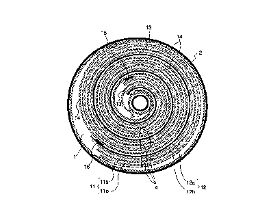
Fig. 1 is a cross sectional view illustrating a
non-aqueous battery having a spirally-wound type
laminate of electrode plates as a first embodiment
according to the present invention;
Fig. 2 is a cross sectional view illustrating
the state of the battery of Fig. 1 when a crushing
force is applied;
Fig. 3 is a cross sectional view illustrating
the state of the battery of Fig. 1 when a sharp
conductive member is pierced into the battery;
Fig. 4 is a cross sectional view illustrating a
non-aqueous battery having a spirally-wound type
laminate of electrode plates as a second embodiment
according to the present invention;
Fig. 5 is a cross sectional view illustrating a
- 19 -
CA 0221161~ 1997-07-2~
non-aqueous battery having a spirally-wound type
laminate of electrode plates as a third embodiment
according to the present invention;
Fig. 6 shows the functions of a center core 3a;
Fig. 7 is a front view illustrating a third
center core 3b;
Fig. 8 is a sectional view taken on the line A-A
of Fig. 7;
Fig. 9 shows the functions of the center core
3b;
Fig. 10 is a front view illustrating a fourth
center core 3c;
Fig. 11 is a front view illustrating a fifth
center core 3d;
Fig. 12 shows a cut-out portion of the fifth
center core 3d;
Fig. 13 is a front view illustrating a sixth
center core 3e;
Fig. 14 is a perspective view illustrating a
seventh center core 3f;
Fig. 15 is a cross sectional view illustrating a
non-aqueous battery having a simple stacked type
l~m; n~te of electrode plates according to the
present invention; and
Fig. 16 is a cross sectional view illustrating a
non-aqueous battery having a zigzag-folded type
- 20 -
- CA 0221161~ 1997-07-2~
l~m; n~te of electrode plates according to the
present invention.
DESCRIPTION OF SYMBOLS
1: Laminate of electrode 2: Battery casing
plates
3: Center core 3a to 3f: Center core
31: Cut-out portion 32: Split opening
(Cut-out portion)
33a to 33c: Slits (Cut-out portions)
34a to 34c: Slits (Cut-out portions)
35: Cut-out portion 35a: Parallel section
(Cut-out portion)
15 35b: Waved section 36: Tapered section
(Cut-out portion)
37: Cut-out portion 37a: Parallel section
(Cut-out portion)
37b: Parallel section 37c: Waved section
(Cut-out portion) (Cut-out portion)
38: Recess 4: Unit cell l~m; n~ te
5: Conductive member 11: Positive plate
lla: Collector foil of llb: Active material of
positive electrode positive electrode
25 12: Negative plate 12a: Collector foil of
negative electrode
- 21 -
-CA 0221161~ 1997-07-2~
12b: Active material of 13: Separator
negative electrode
14: Insulating film 15: Tab on positive
electrode
S 16: Tab on negative electrode
BEST MODES FOR CARRYING OUT THE INVENTION
The following describes some embodiments of the
present invention based on the accompanying
drawings.
Fig. 1 is a cross sectional view illustrating a
non-aqueous battery having a spirally-wound type
l~m;n~te of electrode plates as a first embodiment
according to the present invention.
The battery is a lithium-ion secondary battery
having a spirally-wound type laminate of electrode
plates 1 accommodated in a cylindrical battery
casing 2. A fine cylindrical center core 3 is
inserted into the winding center of the laminate of
electrode plates 1. The center core 3 functions as
a flow path for leading the gas in the battery
casing 2 to the safety valve in case that the
internal pressure of the battery casing 2 is
increased, and is composed of, for example,
stainless steel.
- CA 0221161~ 1997-07-2~
The laminate of electrode plates 1 includes a
positive plate 11 having an active material of
positive electrode llb that contains LiCoO2 and is
applied only on a single face of an aluminum
5 collector foil lla, a negative electrode 12 having
an active material of negative electrode 12b that
contains carbon particles and is applied only on a
single face of a copper collector foil 12a, a
separator 13 composed of a polyethylene fine porous
10 membrane and arranged between the active material of
positive electrode llb and the active material of
negative electrode 12b, and an insulating film 14
composed of the same membrane as that of the
separator 13 and arranged between the collector foil
15 lla of the positive electrode and the collector foil
12a of the negative electrode.
The li3mi n~te of electrode plates 1 is obtained
by laying the collector foil lla of the positive
electrode, the active material of positive electrode
20 llb, the separator 13, the active material of
negative electrode 12b, the collector foil 12a of
the negative electrode, and the insulating film 14
one upon another in this sequence, winding the
layers with the insulating film 14 arranged inside
25 (that is, the collector foil lla of the positive
electrode arranged outside) with a winding machine,
- 23 -
- CA 0221161~ 1997-07-2~
and further winding the insulating film 14 as an
outer-most layer. The laminate of electrode plates
1 accordingly has the layers of the insulating film
14, the collector foil lla of the positive
electrode, the active material llb of positive
electrode, the separator 13, the active material of
negative electrode 12b, the collector foil 12a of
the negative electrode, the insulating film 14, the
collector foil lla of the positive electrode, and so
on, inward from the side of the battery casing 2.
In the l~m; n~ te of electrode plates 1, the
positive electrode 11 and the negative electrode 12
with the active material of positive electrode lla
and the active material of negative electrode 12a
arranged to face each other and the separator 13
disposed therebetween constitute a unit cell
l~m; n~te 4. Whereas the cell reactions proceed in
the unit cell l~m; n~te 4, no cell reactions occur in
the place between the unit cell l~m; n~tes 4, where
the insulating film 14 is disposed tthat is, between
the collector foils lla and 12a of the positive
electrode and the negative electrode).
Referring to Fig. 2, in case that the battery is
crushed in a heaping direction, the inner-most
separator 13 and insulating film 14 close to the
center core 3 generally receive the greatest stress.
- 24 -
- CA 0221161~ 1997-07-2~
,
Breaking thus first occurs in the separator 13 and
the insulating film 14 and is extended toward the
outer circumference. This leads to a short circuit
between the active material of positive electrode
llb and the active material of negative electrode
12b, for example, at positions B and C in Fig. 2.
Substantially at the same time, a short circuit
occurs between the collector foils lla and 12a of
the positive electrode and the negative electrode at
positions A and D. This structure enables most of
the electric current to flow through the collector
foils lla and 12a even in the short-circuited
portions and to be safely discharged inside. This
accordingly decreases the electric current flowing
through the active material of positive electrode
llb containing LiCoO2 and prevents an increase in
temperature of LiCoO2.
Even when a short circuit occurs in a charging
state, this structure effectively inhibits evolution
of oxygen caused by the increased temperature of
LiCoO2 and reactions of aluminum (the collector foil
of the positive electrode) and an organic solvent
(electrolytic solvent) with oxygen, thereby
preventing a large energy from being produced inside
the battery and ensuring the safety of the battery.
Referring to Fig. 3, in case that a sharp
- 25 -
- CA 0221161~ 1997-07-2~
conductive member 5, such as a nail, is pierced into
the battery casing 2 and enters the inside of the
battery, the point of the conductive member 5 that
has become a negative electrode when passing through
the battery casing 2 successively passes through and
comes into contact with the insulating film 14, the
collector foil lla of the positive electrode, the
active material of positive electrode llb, the
separator 13, the active material of negative
electrode 12b, the collector foil 12a of the
negative electrode, the insulating film 14, and so
on in this sequence. At this moment, a short
circuit occurs between the active material of
positive electrode llb and the active material of
negative electrode 12b across the conductive member
5. As discussed above, substantially at the same
time, a short circuit also occurs between the
collector foils lla and 12a of the positive
electrode and the negative electrode. This
structure enables most of the electric current to
flow through the collector foils lla and 12a even in
the short-circuited portions and to be safely
discharged inside. Even when a short circuit occurs
in a charging state, this structure effectively
prevents a large energy from being produced inside
the battery and ensures the safety of the battery.
- 26 -
CA 0221161~ 1997-07-2~
In case that the conductive member 5, such as a
nail, is pierced into the battery casing 2 but does
not reach the center core 3, the conductive member 5
comes into contact with the collector foil lla of
the positive electrode prior to contact with the
active material of positive electrode llb. Even in
short-circuited portions, most of the electric
current thus flows through the collector foil lla of
the positive electrode, whereas substantially no
electric current flows through the active material
of positive electrode llb. The battery has
desirable safety especially when the sharp
conductive member 5, such as a nail, is pierced to a
little extent in the heaping direction.
In the first embodiment, the insulating film 14
disposed between the unit cell laminates 4 (that is,
between the collector foil lla of the positive
electrode and the collector foil 12a of the negative
electrode) is composed of the same membrane as that
of the separator 13. This structure ensures the
safety of the battery since no cell reactions take
place between the unit cell laminates 4, but a
decrease in electric capacity is inevitable. In
case that the positive plate and the negative plate
of the above structure and of the conventional
structure are wound by a fixed length, the battery
- 27 -
CA 0221161~ 1997-07-2~
of the first embodiment has only half the capacity
of the conventional battery. Since the active
materials are applied only on the single faces of
the positive electrode and the negative electrode,
even in case that the winding length of the positive
electrode and the negative electrode of the above
structure is greater than the same of the
conventional structure, the battery of the first
embodiment does not have the capacity of the same
level as that of the conventional battery.
Referring to Fig. 4, when the insulating film 14
is composed of a membrane having a less thickness
than that of the separator 13, a greater length of
the unit cell laminates 4 can be wound in the
battery casing 2 of a fixed size. This structure
desirably increases the electric capacity while
ensuring the safety of the battery. By way of
example, whereas the membrane of the separator 13
generally has the thickness of 25 to 35 ~m, an
insulating membrane of 12 ~m in thickness (for
example, polypropylene resin membrane) is applied
for the insulating film 14. This increases the
initial capacity by approximately 8 to 10% when the
battery casing 2 has a diameter of 18 mm and a
height of 65 mm.
In the battery of the first embodiment, the
- 28 -
CA 0221161~ 1997-07-2~
battery casing 2 and the positive plate 11 face each
other across the insulating film 14. When the
insulating film 14 has an ion-conductive function,
charging and discharging may occur between the
positive plate 11 and the battery casing 2
functioning as the negative electrode. This may
result in deposit of metal lithium on the battery
casing 2 in the charging state and dissolution of
the material of the battery casing 2 in the over
discharging state. The membrane having no ion-
conductive function, for example, a polypropylene
resin membrane, is thus used as the insulating film
14. This effectively prevents deposit of metal
lithium on the battery casing 2 in the charging
state and dissolution of the material of the battery
casing 2 in the over discharging state.
It is preferable that the material of the
insulating film 14 has a lower melting point than
that of the separator 13. In case that an abnormal
heat is externally applied to the battery, this
structure enables the insulating film 14 to be fused
prior to the separator 13. A short circuit between
the collector foils lla and 12a of the positive
electrode and the negative electrode facing each
other across the insulating film 14 accordingly
occurs prior to a short circuit between the active
- 29 -
CA 0221161~ 1997-07-2~
material of positive electrode llb and the active
material of negative electrode 12b facing each other
across the separator 13. This enables the short-
circuiting current not to flow through the active
material of positive electrode llb but to flow only
through the collector foils lla and 12a. When the
melting point of the insulating film 14 is lower
than the melting point of the separator 13, the
structure of the above embodiment ensures desirable
safety in case that an abnormal heat is externally
applied to the battery.
The battery of the first embodiment includes the
spirally-wound type l~m; n~te of electrode plates 1
obtained by laying the unit cell l~m; n~te 4, which
consists of the negative plate 12, the separator 13,
and the positive plate 11, and the insulating film
14 one upon the other in the above manner and
winding the layers in a spiral form with a winding
machine. The lam; n~te of electrode plates in the
battery of the present invention may, however, be
the simple stacked type, wherein the unit cell
l~m; n~tes 4 are laid one upon another and parallel
to one another across the insulating films 14 as
shown in Fig. 15, or the zigzag-folded type, wherein
the layers of the unit cell laminates 4 and the
insulating films 14 are folded at predetermined
- 30 -
CA 0221161~ 1997-07-2~
widths to be arranged in parallel as shown in Fig.
16.
Although the first embodiment regards the
lithium-ion secondary battery, the principle of the
present invention is also applicable to other non-
aqueous secondary batteries and non-aqueous primary
batteries having the active material of relatively
high durability, in order to ensure the safety of
such batteries.
Fig. 5 is a cross sectional view illustrating
another non-aqueous battery with a second center
core 3a inserted therein, in place of the center
core 3 of the first embodiment shown in Fig. 1. The
center core 3a is a hollow cylindrical body having a
cut-out portion 31 of a predetermined width (for
example, 0.3 mm in the cylindrical body of 4.0 mm in
outer diameter and 0.4 mm in thickness) extending in
the axial direction on the circumferential surface
thereon. In case that the battery is crushed in a
heaping direction, as shown by the phantom line in
Fig. 6, the center core 3a is crushed to open the
edges of the cut-out portion 31 outward and break
the laminate of electrode plates 1 from the inner
circumferential side. This accelerates the short
circuit between the collector foils lla and 12a of
the positive electrode and the negative electrode
CA 0221161~ 1997-07-2~
and expands the range of short circuits.
Fig. 7 is a front view illustrating a third
center core 3b, and Fig. 8 is a sectional view taken
on the line A-A of Fig. 7. Fig. 8 clearly shows the
function of the center core 3b.
The center core 3b is composed of stainless
steel, for example, SUS304. As shown in Figs. 7 and
8, the center core 3b is a hollow cylindrical body
having a split opening 32 of a predetermined width
(for example, 0.3 mm in the cylindrical body of 4.0
mm in outer diameter and 0.4 mm in thickness) that
extends in the axial direction on the
circumferential surface thereof, like the cut-out
portion 31, as well as slits 33a through 33c and 34a
through 34c of the predetermined width that extend
in the axial direction but do not reach the end face
of the cylindrical body.
The slits 33a through 33c are arranged in series
at predetermined intervals along one straight line
parallel to the axis, whereas the slits 34a through
34c are arranged in series at predetermined
intervals along another straight line parallel to
the axis. The split opening 32, the slits 33a
through 33c, and the slits 34a through 34c are
arranged to divide the circumference of the circular
cross section of the center core 3b into three e~ual
CA 0221161~ 1997-07-2~
portions.
In case that the battery of Fig. 1 having the
center core 3b is crushed in a heaping direction,
the center core 3b is crushed to open the edges of
the split opening 32 and the slits 33a through 33c
and 34a through 34c outward and break the laminate
of electrode plates 1 from the inner circumferential
side. This accelerates the short circuit and
expands the range of short circuits.
Especially when the crushing direction of the
battery coincides with one of the cut-out portions
of the center core 3b (the split opening 32 in this
example) as shown by the phantom line in Fig. 9, the
edges of the split opening 32 are pressed inward and
do not break the laminate of electrode plates 1,
while the edges of the slits 33a through 33c and 34a
through 34c open outward. This structure enables
the laminate of electrode plates 1 to be securely
broken irrespective of the crushing direction.
Compared with the center core 3a, the center core 3b
causes a greater number of short circuits in the
circumferential direction of the l~m; n~te of
electrode plates 1.
Fig. 10 is a front view illustrating a fourth
center core 3c. AS clearly seen in this drawing,
the center core 3c corresponds to the center core 3a
CA 0221161~ 1997-07-2~
with the cut-out portion 31 having the triangular-
waved edges except both ends in the longitudinal
direction. A cut-out portion 35 of the center core
3c includes parallel sections 35a formed on both
ends in the longitudinal direction and a central
waved section 35b. The center core 3c also has
tapered sections 36 on both ends in the longitudinal
direction, in order to allow the center core 3c to
be readily inserted into the winding center of the
laminate of electrode plates 1. The diameter of
each tapered section 36 decreases toward the
corresponding end.
When the center core 3c is crushed by the
crushing force applied to the laminate of electrode
plates 1 in a heaping direction, the edges of the
waved section 35b opened outward form a serrated
protrusion. This enables the laminate of electrode
plates 1 to be more readily broken and better
disperses the broken positions than the structure of
the first embodiment.
Fig. 11 is a front view illustrating a fifth
center core 3d. As clearly seen in this drawing,
the center core 3d is a cylindrical body having a
spiral cut-out portion 37 that is formed on the
circumferential surface of the cylindrical body to
extend in a direction L1 (actually in a spiral form)
- 34 -
CA 0221161~ 1997-07-2~
obliquely intersecting an axial direction LO of the
cylindrical body and run from one end to the other
end in the longitudinal direction. The spiral cut-
out portion 37 includes parallel sections 37a and
37b formed on both ends in the longitudinal
direction to be parallel to the direction Ll, and a
central waved section 37c having triangular-waved
edges. As shown in Fig. 12, the spiral of the cut-
out portion 37 is formed to rotate by 90 degrees
between one end 37A and the other end 37B in the
longitudinal direction. The center core 3d also has
tapered sections 36 on both ends in the longitudinal
direction, in order to allow the center core 3d to
be readily inserted into the winding center of the
laminate of electrode plates 1. The diameter of
each tapered section 36 decreases toward the
corresponding end.
When the center core 3d is crushed by the
crushing force applied to the laminate of electrode
plates 1 in a heaping direction, the edges of the
cut-out portion 37 are opened outward irrespective
of the crushing direction that intersects the axis,
thereby enabling the l~m; n~te of electrode plates 1
to be securely broken. The edges of the waved
section 37c opened outward form a serrated
protrusion. This enables the laminate of electrode
- 35 -
- CA 0221161~ 1997-07-2~
plates 1 to be more readily broken and better
disperses the broken positions. Compared with the
structure having a plurality of cut-out portions
that are arranged in the circumferential direction
and extend in the axial direction, this structure is
effective for the crushing force applied in any
direction intersecting the axis, while decreasing
the opening area on the circumferential surface.
The center core of less thickness can accordingly
hold the required strength in the ordinary state.
Fig. 13 is a front view illustrating a sixth
center core 3e. The center core 3e is a solid
screwed shaft having the diameter of approximately 4
mm and the pitch of 0.7 mm and has a spiral recess
31 formed on the circumferential surface thereof.
The depth of the recess 31 ((diameter of the thread
crest - diameter of the thread bottom) /2) is
approximately 0.5 mm.
When the battery is crushed in a heaping
direction, the inner circumferential side of the
l~m; n~te of electrode plates 1 is cut into the
recess 31 of the center core 3d and broken
extensively.
Fig. 14 is a perspective view illustrating a
seventh center core 3f. The center core 3f is a
stainless steel coiled spring that is composed of
- 36 -
- CA 0221161~ 1997-07-2~
wires of circular cross section, wherein the
diameter of the wires and the pitch are respectively
0.6 mm and 1.6 mm. There is a clearance of 1.0 mm
between the adjoining wires in a non-loading
condition.
When the battery is crushed in a heaping
direction, the inner circumferential portion of the
l~m; n~te of electrode plates 1 is pressed against
the circumferential surface of the coiled spring 3f.
The coiled spring 3f is crushed and extends in the
axial direction to be inclined in the laminate of
electrode plates 1 (that is, the center axis of the
coiled spring 3f is deacrossted from the winding
center), while the inner circumferential portion of
the laminate of electrode plates 1 is cut into the
clearance between the adjoining wires. This enables
the l~mi n~te of electrode plates 1 to be extensively
broken from the inner circumferential side.
FIELD OF INDUSTRIAL APPLICATIONS
AS discussed above, the non-aqueous battery of
the present invention can effectively prevent an
abrupt increase in internal temperature even when a
short circuit occurs between an active material of
positive electrode and a negative electrode due to
- 37 -
CA 0221161~ 1997-07-2~
external application of an abnormal heat, a crush of
the battery in a heaping direction, or a pierced
nail in an over charging state, thereby ensurin~ the
safety of the battery.
- 38 -