Note : Les descriptions sont présentées dans la langue officielle dans laquelle elles ont été soumises.
CA 02211925 1997-10-16
DOWNLINK TRANSMISSION POWER CONTROL SCHEME FOR
MOBILE COMMUNICATION SYSTEM USING S3TE DIVERSITY
BACKGROUND OF THE INVENTION
FIELD OF THE INVENTION
The present invention relates to a downlink
transmission power control scheme for realizing an
efficient transmission power control with respect to
downlink radio signals which are transmitted from base
stations to a mobile station via radio channels in a mobile
communication system using a site diversity.
DESCRIPTION OF THE BACKGROUND ART
A radio communication scheme can incorporate a
transmission power control for the purpose of suppressing a
transmission power to a minimum necessary level. By
carrying out this transmission power control, it is
possible to realize such advantageous effects as a saving
of power consumption and a reduction of interferences with
respect to other radio channels. In particular, in the CDMA
(Code Division Multiple Access) scheme, a lower amount of
interferences directly implies a larger subscriber
capacity, so that the transmission power control is an
indispensable technique.
On the other hand, one known technique for reducing
interferences in the CDMA scheme is the site diversity,
which is a technique in which a mobile station and a
plurality of base stations are simultaneously connected and
a diversity combining is carried out among a plurality of
base stations. This site diversity is capable of satisfying
a given communication quality by using a less transmission
power, so that the interferences can be reduced and the
subscriber capacity can be increased.
-1-
CA 02211925 1997-10-16
Now, in the radio communication in general, the
propagation loss is not identical for the uplink channel
from a mobile station to a base station and the downlink
channel from a base station to a mobile station.
Consequently, in order to improve the transmission power
control precision, it is preferable to carry out the closed
loop transmission power control.
In the closed loop transmission power control, a base
station transmission power in a downlink communication
channel is controlled by a transmission power control
signal according to a receiving quality measured at a
mobile station as indicated in a part (b) of Fig. 1, while
a mobile station transmission power in an uplink
communication channel is controlled by a transmission power
control signal according to a receiving quality measured at
a base station as indicated in a part (a) of Fig. 1.
For example, such a closed loop transmission power
control can be realized by using one bit information as
follows. Namely, a receiving side transmits to a
transmitting side a transmission power control command
which indicates "0" when the receiving quality measured at
the receiving side does not satisfy a required quality, or
"1" when the receiving quality measured at the receiving
side satisfies the required quality. Then, at the
transmitting side, the transmission power is raised by one
step when the transmission power control command indicates
"0", or lowered by one step when the transmission power
control command indicates "1". By carrying out this control
continuously, it is possible to maintain the receiving
quality nearly at a level of the required quality.
This closed loop transmission power control can be
realized by using either a control signal which is
terminated between a mobile station and a base station, or
a control signal which is terminated between a mobile
station and a base station control station. In the latter
-2-
CA 02211925 1997-10-16
case, the control signal transmitted by a mobile station is
received by a plurality of base stations-and combined
during a site diversity period, and then transmitted to a
base station control station.
The control signal terminated between a mobile station
and a base station is usually transmitted on layer-1, and
will be referred to as the layer-1 control signal. The
control signal terminated between a mobile station and a
base station control station is usually transmitted on
layer-3, and will be referred to as the layer-3 control
signal.
In a case of realizing the closed loop transmission
power control, a higher transmission power control
precision can be realized by a shorter transmission power
control period. From this point of view, it is more
convenient to transmit the transmission power control
signal as the layer-1 control signal, because the layer-1
control signal does not require the encoding processing or
the re-transmission processing so that a very fast
transmission power control can be realized.
Fig. 2 shows an exemplary case of the downlink
transmission power control using the layer-1 control
signal. In this case, a loop is formed between a mobile
station and a base station, so that it is possible to
realize a fast transmission power control with a small
control delay and therefore it is possible to reduce a
transmission power control error.
However, the layer-1 control signal is to be received
independently by each base station, so that there is a
problem in realizing the control during a site diversity
period. Namely, when a control for maintaining a quality
after the site diversity combining above a certain level is
carried out in the uplink channel, it becomes impossible to
maintain a sufficient uplink receiving quality at some base
station among a plurality of base stations that are
-3-
CA 02211925 1997-10-16
simultaneously connected with a mobile station, so that
there is a possibility for raising an error rate of the
layer-1 control signal transmitted from a mobile station to
a base station. At such a base station, the transmission
power control error becomes large so that an amount of
interferences is increased and this in turn causes a
lowering of a capacity in a case of the CDMA mobile
communication system.
Fig. 3 shows an exemplary case of the downlink
transmission power control using the layer-3 control
signal. In this case, during a site diversity period, the
layer-3 control signal is combined at an exchange station
and then transmitted to a base station control station.
Consequently, the reliability of the layer-3 control signal
is quite high and the transmission powers of the base
stations are always controlled uniformly according to the
same information.
However, due to the transmission delay of the layer-3
control signal, it is impossible to realize a fast
transmission power control, and a capacity is lowered as
the transmission power control error becomes large. In
addition, there is also a problem that an amount of control
signals to be transmitted between a base station and a base
station control station is increased.
Conventionally, the closed loop transmission power
control has been realized either by always using the layer-
3 control signal as in a case of Fig. 3, or by always using
the layer-1 control signal as in a case of Fig. 2.
Thus, when the transmission power control by always
using the layer-1 control signal is carried out in a mobile
communication system using the site diversity, there arises
a problem of an increased transmission power control error
during a site diversity period. On the other hand, when the
transmission power control by always using the layer-3
control signal is carried out in a mobile communication
-4-
CA 02211925 1997-10-16
system using the site diversity, there arises a problem of
an increased transmission power control error and an
increased amount of signals transmitted between stations
during a non-site diversity period. Here, an increased
transmission power control error can cause an increase of
interferences which in turn can cause a lowering of a
capacity in the CDMA mobile communication system.
SUMMARY OF THE INVENTION
It is therefore an object of the present invention to
provide a downlink transmission power control scheme for a
mobile communication system using the site diversity, which
is capable of improving the transmission power control
precision, and reducing an amount of interferences and
thereby increasing a capacity in a case of the CDMA mobile
communication system.
It is another object of the present invention to
provide a downlink transmission power control scheme for a
mobile communication system using the site diversity, which
is capable of realizing the transmission power control with
a small control error and a less amount of signals to be
transmitted between stations.
It is another object of the present invention to
provide a downlink transmission power control scheme for a
mobile communication system using the site diversity, which
is capable of realizing a small transmission power control
error during a site diversity period even when a
transmission power control signal terminated between a
mobile station and a base station is used.
According to one aspect of the present invention there
is provided a method of downlink transmission power control
in a mobile communication system formed by a plurality of
base stations, a mobile station to be connected with the
-5-
CA 02211925 1997-10-16
base stations via radio channels, and a base station
control station for controlling the base-stations, wherein
the mobile communication system uses a site diversity in
which the mobile station is simultaneously connected with
more than one base stations and a diversity combining among
said more than one base stations is carried out, the method
comprising the steps of: carrying out a primary downlink
transmission power control using a primary control signal
which is transmitted from the mobile station and terminated
at each base station and not to be combined during a site
diversity period; and carrying out an additional downlink
transmission power control using additional control signals
which are transmitted from the base station control station
to the base stations.
According to another aspect of the present invention
there is provided a mobile communication system,
comprising: a plurality of base stations; a mobile station
to be connected with the base stations via radio channels,
which transmits a primary control signal which is to be
terminated at each base station and not to be combined
during a site diversity period so as to carry out a primary
downlink transmission power control at each base station
according to the primary control signal; and a base station
control station for controlling the base stations, which
transmits additional control signals to the base stations
so as to carry out an additional downlink transmission
power control at the base stations according to the
additional control signals; wherein the mobile
communication system uses a site diversity in which the
mobile station is simultaneously connected with more than
one base stations and a diversity combining among said more
than one base stations is carried out.
Other features and advantages of the present invention
will become apparent from the following description taken
in conjunction with the accompanying drawings.
-6-
CA 02211925 1997-10-16
BRIEF DESCRIPTION OF THE DRAWINGS
Fig. 1 is a diagram showing a conventional closed loop
transmission power control.
Fig. 2 is a diagram showing a conventional downlink
transmission power control using a layer-1 control signal.
Fig. 3 is a diagram showing a conventional downlink
transmission power control using a layer-3 control signal.
Fig. 4 is a schematic block diagram of a mobile
communication system for realizing a downlink transmission
power control scheme according to the present invention.
Fig. 5 is a schematic diagram of a mobile
communication system showing the most basic embodiment of a
downlink transmission power control scheme according to the
present invention.
Fig. 6 is a schematic sequence chart showing the most
basic embodiment of a downlink transmission power control
scheme according to the present invention.
Fig. 7 is a schematic diagram of a mobile
communication system showing the first basic embodiment of
a downlink transmission power control scheme according to
the present invention.
Fig. 8 is a schematic sequence chart showing the
second basic embodiment of a downlink transmission power
control scheme according to the present invention.
Fig. 9 is a schematic sequence chart showing the third
basic embodiment of a downlink transmission power control
scheme according to the present invention.
Fig. 10 is a schematic diagram of a mobile
communication system showing the fourth basic embodiment of
a downlink transmission power control scheme according to
the present invention.
Fig. 11 is a block diagram of a mobile station in the
-7-
CA 02211925 1997-10-16
mobile communication system of Fig. 4 according to the
first specific embodiment of the present-invention.
Fig. 12 is a block diagram of a base station in the
mobile communication system of Fig. 4 according to the
first specific embodiment of the present invention.
Fig. 13 is a diagram showing an exemplary downlink
transmission power control using the layer-1 control signal
during the non-site diversity period in the first specific
embodiment of the present invention.
Fig. 14 is a diagram showing one part of an exemplary
downlink transmission power control using the layer-3
control signal during the site diversity period in the
first specific embodiment of the present invention.
Fig. 15 is a diagram showing another part of an
exemplary downlink transmission power control using the
layer-3 control signal during the site diversity period in
the first specific embodiment of the present invention.
Fig. 16 is a sequence chart showing an exemplary
procedure for switching transmission power control modes
according to the first specific embodiment of the present
invention.
Fig. 17 is a table showing exemplary layer-3 control
signal contents that can be used in the first specific
embodiment of the present invention.
Fig. 18 is a block diagram of a mobile station in the
mobile communication system of Fig. 4 according to the
second to seventh specific embodiments of the present
invention.
Fig. 19 is a block diagram of a base station in the
mobile communication system of Fig. 4 according to the
second to seventh specific embodiments of the present
invention.
Fig. 20 is a sequence chart showing an exemplary
downlink transmission power control procedure in the second
specific embodiment of the present invention.
_g_
CA 02211925 1997-10-16
Fig. 21 is a sequence chart showing an exemplary
downlink transmission power control procedure in the third
specific embodiment of the present invention.
Fig. 22 is a schematic diagram of a mobile
communication system showing the fifth specific embodiment
of a downlink transmission power control scheme according
to the present invention.
Fig. 23 is a table showing exemplary perch channel and
communication channel receiving SIRs for explaining the
fifth specific embodiment of the present invention.
Fig. 24 is a graph showing exemplary base station
transmission powers for explaining the sixth specific
embodiment of the present invention.
Fig. 25 is a schematic diagram of a mobile
communication system showing the sixth specific embodiment
of a downlink transmission power control scheme according
to the present invention.
Fig. 26 is a schematic diagram of a mobile
communication system showing the seventh specific
embodiment of a downlink transmission power control scheme
according to the present invention.
DETAILED DESCRIPTION OF THE PREFERRED EMBODIMENTS
Referring now to Fig. 4 to Fig. 10, some basic
embodiments of a downlink transmission power control scheme
for a mobile communication system using the site diversity
according to the present invention will be described.
In the following description, a control signal which
is terminated between a mobile station and a base station
and which is not to be combined at an exchange station
during a site diversity period will be referred to as the
layer-1 control signal, although such a control signal is
not necessarily limited to dust the layer-1 control signal
-9-
CA 02211925 1997-10-16
in general and the layer-1 control signal is not required
to have this characteristic by definition in general. This
layer-1 control signal is also referred to as a
transmission power control command or a power control bit
in practice. Also, a control signal which is terminated
between a mobile station and a base station control station
and which is to be combined at an exchange station during a
site diversity period will be referred to as the layer-3
control signal, although such a control signal is not
necessarily limited to just the layer-3 control signal and
the layer-3 control signal is not required to have this
characteristic by definition in general. Note also that a
base station control station is functionally separated from
an exchange station in the following description, although
a function of a base station control station can be
integrally incorporated into an exchange station without
providing physically separate base station control station
and exchange station in some practical system
configuration.
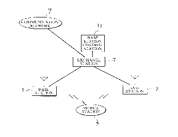
Fig. 4 shows a schematic configuration of a mobile
communication system for realizing the downlink
transmission power control scheme of the present invention.
In this mobile communication system of Fig. 4, a
mobile station 5 is connected with base stations 1 and 2
via radio channels, while the base stations 1 and 2 are
connected with a base station control station 11 and a
communication network 9 via an exchange station 7. This
mobile communication system has a site diversity function
so that the mobile station 5 can be simultaneously
connected with the plural base stations 1 and 2 by setting
up respective radio channels and the diversity combining
can be carried out among the plural base stations 1 and 2.
The exchange station 7 has a function for connecting
channels from the base stations 1 and 2 with channels from
the communication network 9, as well as a function for
-10-
CA 02211925 1997-10-16
combining signals received at the plural base stations 1
and 2 and a function for distributing signals from the
communication network 9 to the plural base stations 1 and 2
during a site diversity period. The base station control
station 11 has a function for controlling the plural base
stations 1 and 2.
In this mobile communication system of Fig. 4, in
order to maintain communications at the mobile station 5,
controls are carried out through radio channels between the
mobile station 5 and the base stations 1 and 2. Control
signals used in these controls are classified into the
layer-1 control signal and the layer-3 control signal. The
layer-1 control signal is to be transmitted on layer-1
between the mobile station 5 and the base stations 1 and 2,
so that it is terminated at the mobile station 5 and the
base stations 1 and 2. The layer-1 control signal is to be
used for a fast control so that it is not to be combined at
the exchange station 7 even during a site diversity period,
and to be received at each base station independently. The
layer-3 control signal is to be transmitted on layer-3
between the mobile station 5 and the base station control
station 11 via the base stations 1 and 2 and the exchange
station 7, so that it is terminated at the mobile station 5
and the base station control station 11.
In the most basic embodiment, as indicated in Fig. 5
and Fig. 6, the layer-1 control signal which is not to be
combined at the exchange station 7 is transmitted from the
mobile station 5 to the base stations 1 and 2 in short time
intervals so as to realize a fast downlink transmission
power control that can follow a variation in the
propagation loss.
However, this downlink transmission power control
using the layer-1 control signal alone is not capable of
realizing an accurate transmission power control for a
plurality of base stations 1 and 2 during a site diversity
-11-
CA 02211925 1997-10-16
period, and the transmission power error at each base
station becomes larger as time elapses. -
For this reason, in the most basic embodiment, as
indicated in Fig. 5 and Fig. 6, an additional downlink
transmission power control is carried out by using
additional control signals which are transmitted from the
base station control station 11 to the base stations 1 and
2 in certain long time intervals so as to further control
the transmission power at each base station.
By means of this combined downlink transmission power
control using the layer-1 control signal from the mobile
station 5 and the additional control signals from the base
station control station 11, it is possible to realize a
high downlink transmission power control precision, and
therefore it is possible to reduce an amount of
interferences and increase a capacity in a case of the CDMA
mobile communication system.
As one specific case of the most basic embodiment
described above, the first basic embodiment shown in Fig. 7
is further characterized in that the additional control
signals transmitted from the base station control station
11 to the base stations 1 and 2 are generated at the base
station control station 11, from the layer-3 control signal
to be combined at the exchange station 7 which is
transmitted from the mobile station 5 to the exchange
station 7 via the base stations 1 and 2, combined at the
exchange station 7, and supplied from the exchange station
7 to the base station control station 11.
As one specific case of the first basic embodiment
described above, the second basic embodiment shown in Fig.
8 is further characterized in that the downlink
transmission power control in short time intervals using
the layer-1 control signal from the mobile station 5 is
carried out during a non-site diversity period, while the
downlink transmission power control in long time intervals
-12-
CA 02211925 1997-10-16
using the additional control signals from the base station
control station 11 based on the layer-3 control signal from
the mobile station 5 is carried out during a site diversity
period.
As another specific case of the first basic embodiment
described above, the third basic embodiment shown in Fig. 9
is further characterized in that the downlink transmission
power control in short time intervals using the layer-1
control signal from the mobile station 5 as well as the
downlink transmission power control in long time intervals
using the additional control signals from the base station
control station 11 based on the layer-3 control signal from
the mobile station 5 are carried out during a site
diversity period.
As another specific case of the basic embodiment
described above, the fourth basic embodiment shown in Fig.
10 is further characterized in that the additional control
signals transmitted from the base station control station
11 to the base stations 1 and 2 are generated at the base
station control station 11, according to a current
transmission power control state of each base station based
on a report from each base station, so as to realize a
centralized downlink transmission power control for all the
base stations.
Referring now to Fig. 11 to Fig. 17, a first specific
embodiment of a downlink transmission power control scheme
for a mobile communication system using the site diversity
according to the present invention, which is a more
specific based on the first and second basic embodiments
described above, will be described in detail.
Fig. 11 shows a configuration of the mobile station 5
in the system of Fig. 4 according to this first specific
embodiment.
In this mobile station configuration of Fig. 11, a
-13-
CA 02211925 1997-10-16
duplexer 15 is provided in order to use an antenna 13 for
both transmission and reception. Signals-received at a
reception radio unit 17 are despread at despreading units
19a and 19b and supplied to a combining unit 21. During a
site diversity period, the combining unit 21 combines
signals which are despread by using a plurality of codes by
the despreading units 19a and 19b, whereas during a non-
site diversity period, only one of the despreading units
19a and 19b despreads the signals and the combining unit 21
does not carry out any combining. A demodulation unit 23
generates a bit sequence from an output of the combining
unit 21. A signal separation unit 25 extracts a user data
and a layer-3 control signal from an output of the
demodulation unit 23, and supplies the user data to a
terminal unit 27 while supplying the layer-3 control signal
to a layer-3 control signal reception unit 29.
A control unit 31 generates a layer-1 control signal
and a layer-3 control signal for the purpose of
transmission power control according to a receiving SIR
(Signal to Interference Ratio) detected by an SIR detection
unit 33 from an output of the demodulation unit 23, a BER
(Bit Error Rate) detected by a BER detection unit 35 from
an output of the combining unit 21, and the layer-3 control
signal received by the layer-3 control signal reception
unit 29. A signal generation unit 37 generates transmission
signals from the layer-1 control signal and the layer-3
control signal generated by the control unit 31 and the
user data supplied from the terminal unit 27. The
transmission signals are then modulated by a modulation
unit 39, spread by a spreading unit 41, and transmitted to
the base stations 1 and 2 from a transmission radio unit 43
via the duplexer 15 and the antenna 13.
Fig. 12 shows a configuration of each one of the base
stations 1 and 2 in the system of Fig. 4 according to this
first specific embodiment.
-14-
CA 02211925 1997-10-16
In this base station configuration of Fig. 12, a
duplexer 47 is provided in order to use-an antenna 45 for
both transmission and reception. This base station
configuration of Fig. 12 has channel-1 to channel-n for the
purpose of carrying out communications with a plurality of
mobile stations. A common transmission amplifier 49 and a
common reception amplifier 51 are to be shared by a
plurality of users, and connected with a plurality of
channel blocks 50-1 to 50-n corresponding to channel-1 to
channel-n. Here, the channel blocks 50-1 to 50-n have an
identical internal configuration so that only the channel
block 50-1 will be described.
In the channel block 50-1, signals received at a
reception radio unit 53 are despread at a despreading unit
55, and then demodulated at a demodulation unit 57 so as to
generate a bit sequence. A signal separation unit 59
extracts a user data, a layer-1 control signal, and a
layer-3 control signal from an output of the demodulation
unit 57, and supplies the user data and the layer-3 control
signal to the exchange station 7 while supplying the layer-
1 control signal to a control unit 61.
The control unit 61 determines a transmission power
according to the layer-1 control signal extracted by the
signal separation unit 59 and the layer-3 control signal
supplied from the base station control station 11, and
specifies the determined transmission power to a
transmission radio unit 71 via a transmission power control
unit 63. In addition, the control unit 61 relays the layer-
3 control signal supplied from the base station control
station 11 through a layer-3 control signal reception unit
73 to a signal generation unit 65. The signal generation
unit 65 then generates transmission signals from the layer-
3 control signal relayed by the control unit 61 and the
user data supplied from the exchange station 7. The
transmission signals are then modulated by a modulation
-15-
CA 02211925 1997-10-16
unit 67, spread by a spreading unit 69, and transmitted to
the mobile station 5 from a transmission radio unit 71 via
the common transmission amplifier 49, the duplexer 47, and
the antenna 45.
Fig. 13 shows an exemplary downlink transmission power
control using the layer-1 control signal during the non-
site diversity period. In this example shown in Fig. 13,
the layer-1 control signal is periodically provided within
a radio frame, and the mobile station 5 notifies the
receiving quality to the base station 1 by this layer-1
control signal, so as to control the transmission power of
the base station 1.
Fig. 14 and Fig. 15 show an exemplary downlink
transmission power control using the layer-3 control signal
during the site diversity period.
Fig. 14 shows an exemplary case in which the mobile
station 5 transmits the layer-3 control signal to the base
station control station 11. The same layer-3 control signal
transmitted by the mobile station 5 is received by the base
station 1 and the base station 2, and respectively
transmitted to the exchange station 7. The exchange station
7 carries out the selective combining of the layer-3
control signal received by the base station 1 and the base
station 2 which selects one with a better quality, and
supplies the selectively combined layer-3 control signal to
the base station control station 11. The mobile station 5
notifies the receiving quality to the base station control
station 11 by this layer-3 control signal. The base station
control station 11 then controls the transmission powers of
the base stations 1 and 2 according to the notified
receiving quality.
Fig. 15 shows an exemplary case in which the base
station control station 11 controls the transmission power
of the base station 1 by transmitting the layer-3 control
signal to the base station 1 via the exchange station 7.
-16-
CA 02211925 1997-10-16
In this first specific embodiment, the transmission
power control modes are to be switched according to the
site diversity state, and Fig. 16 shows an exemplary
procedure for switching transmission power control modes.
In a process (1) of Fig. 16, the mobile station 5 is
connected with the base station 1. It is not during the
site diversity period at this point, so that the
transmission power control using the layer-1 control signal
is carried out.
In a process (2) of Fig. 16, the base station control
station 11 decides a start of the site diversity, and
notifies this decision to the mobile station 5 and the base
stations 1 and 2. Each of the mobile station 5 and the base
stations 1 and 2 which received this notice then switches
the transmission power control using the layer-1 control
signal to the transmission power control using the layer-3
control signal.
In a process (3) of Fig. 16, the transmission power
control using the layer-3 control signal is carried out, so
that the mobile station 5 transmits the layer-3 control
signal to the base station control station 11. Then, the
base station control station 11 carries out the
transmission power control with respect to the base
stations 1 and 2 by using the layer-3 control signal.
In a process (4) of Fig. 16, the base station control
station 11 decides an end of the site diversity, and
notifies this decision to the mobile station 5 and the base
stations 1 and 2. Each of the mobile station 5 and the base
stations 1 and 2 which received this notice then switches
the transmission power control using the layer-3 control
signal to the transmission power control using the layer-1
control signal. In this example, the mobile station 5
releases the connection with the base station 1 and is
connected only with the base station 2.
In a process (5) of Fig. 16, the transmission power
-17-
CA 02211925 1997-10-16
control using the layer-1 control signal is carried out
between the mobile station 5 and the bass station 2.
In this manner, the downlink transmission power
control using the layer-1 control signal is carried out
during the non-site diversity period so that the control
delay and the control error can be made smaller and an
amount of control signals to be transmitted between
stations can be reduced. Also, the downlink transmission
power control using the layer-3 control signal is carried
out during the site diversity period so that the
transmission powers of all the base stations can be
controlled at high precision. Moreover, by separately using
two types of transmission power control methods depending
on whether the site diversity is carried out or not in this
manner, it is possible to realize the transmission power
control with a smaller control error and therefore it is
possible to increase a downlink capacity.
Next, an exemplary case of carrying out the
transmission power control using the layer-1 control signal
according to the receiving SIR and the transmission power
control using the layer-3 control signal according to the
error rate will be described with reference to Fig. 11.
In the mobile station 5, the control unit 31 can
recognizes the site diversity state from the layer-3
control signal received at the layer-3 control signal
reception unit 29. When it is not during the site diversity
period, the control unit 31 determines the layer-1 control
signal from the receiving SIR detected by the SIR detection
unit 33, and sends this layer-1 control signal to the
signal generation unit 37. For example, the receiving SIR
is compared with a reference SIR, and the layer-1 control
signal is set to indicate "0" when the receiving SIR is
smaller than the reference SIR or "1" otherwise. At the
base station which received this layer-1 control signal,
the transmission power is raised by one step when the
-18-
CA 02211925 1997-10-16
layer-1 control signal indicates "0", or lowered by one
step when the layer-1 control signal indicates "1". By
carrying out this control continuously, it is possible to
maintain the receiving quality at the mobile station nearly
constant.
On the other hand, when it is during the site
diversity period, the control unit 31 determines the layer-
3 control signal from the BER detected by the BER detection
unit 35, and sends this layer-3 control signal to the
signal generation unit 37. It is also possible to replace
the BER detection unit 35 of Fig. 11 with an FER (Frame
Error Rate) detection unit, so as to use the FER instead of
the BER. Exemplary layer-3 control signal contents are
shown in Fig. 17, which vary according to the BER values.
The base station control station 11 which received this
layer-3 control signal then determines a base station
transmission power control amount for each base station
according to the notified BER or FER, and notifies the
determined control amount to each base station by using the
layer-3 control signal. In response, each base station
controls its transmission power as commanded by the base
station control station 11.
In this example, the transmission power control using
the layer-1 control signal is carried out according to the
receiving SIR so as to be able to follow an instantaneous
variation, while the transmission power control using the
layer-3 control signal is carried out according to the bit
error rate or the frame error rate so as to reduce an
influence of delay time as well as an amount of control
signals to be transmitted between stations, so that a
transmission power control error can be made smaller and a
downlink capacity can be increased.
Next, as another exemplary case, it is also possible
to carry out the transmission power control using the
layer-1 control signal according to the receiving SIR of
-19-
CA 02211925 1997-10-16
the communication channel during the non-site diversity
period as in the previous example, while--carrying out the
transmission power control using the layer-3 control signal
according to a receiving SIR of the perch channel instead
of the error rate used in the previous example during the
site diversity period.
In this example, the transmission power control based
on the receiving SIR is also carried out during the site
diversity period so that the BER or FER measurement at the
mobile station becomes unnecessary. In addition, it also
becomes possible to realize a relatively fast transmission
power control during the site diversity period even though
the layer-3 control signal is still used.
Next, an exemplary case of carrying out both of the
transmission power control using the layer-1 control signal
and the transmission power control using the layer-3
control signal according to the bit error rate or frame
error rate will be described with reference to Fig. 11.
In the mobile station 5, the control unit 31 can
recognizes the site diversity state from the layer-3
control signal received at the layer-3 control signal
reception unit 29. When it is not during the site diversity
period, the control unit 31 determines the layer-1 control
signal from the BER detected by the BER detection unit 35,
and sends this layer-1 control signal to the signal
generation unit 37. Here, the FER may be used instead of
the BER. For example, the detected BER (FER) is compared
with a reference BER (FER), and the layer-1 control signal
is set to indicate "0" when the detected BER (FER) is
smaller than the reference BER (FER) or "1" otherwise. At
the base station which received this layer-1 control
signal, the transmission power is raised by one step when
the layer-1 control signal indicates "0", or lowered by one
step when the layer-1 control signal indicates "1". By
carrying out this control continuously, it is possible to
-20-
CA 02211925 1997-10-16
maintain the receiving quality at the mobile station nearly
constant. -
On the other hand, when it is during the site
diversity period, the control unit 31 determines the layer-
s 3 control signal from the BER detected by the BER detection
unit 35, and sends this layer-3 control signal to the
signal generation unit 37. Here, the FER may be used
instead of the BER similarly. Exemplary layer-3 control
signal contents in this case are similar to those shown in
Fig. 17. The base station control station 11 which received
this layer-3 control signal then determines a base station
transmission power control amount for each base station
according to the notified BER or FER, and notifies the
determined control amount to each base station by using the
layer-3 control signal. In response, each base station
controls its transmission power as commanded by the base
station control station 11.
In this example, both of the transmission power
control using the layer-1 control signal and the
transmission power control using the layer-3 control signal
are carried out according to the bit error rate or frame
error rate, so that the measurement of the receiving SIR at
the mobile station becomes unnecessary and the switching of
measurement procedures at the mobile station also becomes
unnecessary. Consequently, the control at the mobile
station can be simplified.
Next, an exemplary case of stopping a transmission of
a bit for the transmission power control using the layer-1
control signal during the site diversity period will be
described with reference to Fig. 11.
In the mobile station 5, the control unit 31 can
recognizes the site diversity state from the layer-3
control signal received at the layer-3 control signal
reception unit 29. When it is during the site diversity
period, the transmission power control using the layer-3
-21-
CA 02211925 1997-10-16
control signal is carried out similarly as in the previous
examples, but at this point, the control- unit 31 also
commands the transmission radio unit 43 to stop the
transmission of a bit corresponding to the layer-1 control
signal. In response, the transmission radio unit 43 stops
the transmission of the layer-1 control signal alone as
commanded by the control unit 31.
In this example, the transmission of a bit for the
layer-1 control signal is stopped during the site diversity
period, so that an amount of interferences in the uplink
channel can be reduced and an uplink capacity can be
increased.
Referring now to Fig. 18 to Fig. 20, a second specific
embodiment of a downlink transmission power control scheme
for a mobile communication system using the site diversity
according to the present invention, which is a more
specific embodiment based on the first and third basic
embodiments described above, will be described in detail.
Fig. 18 shows a configuration of the mobile station 5
in the system of Fig. 4 according to this second specific
embodiment.
In this mobile station configuration of Fig. 18, a
duplexer 115 is provided in order to use an antenna 113 for
both transmission and reception. Signals received at a
reception radio unit 117 are despread by using prescribed
codes at a plurality of despreading units 119a, 119b and
119c. During a site diversity period, the despreading unit
119a despreads a downlink communication channel from the
base station 1 while the despreading unit 119b despreads a
downlink communication channel from the base station 2. The
despread signals are then combined at a demodulation unit
121a so as to generate a bit sequence. Also, an SIR
detection unit 123a detects a receiving SIR of the
communication channel from an output of the demodulation
-22-
CA 02211925 1997-10-16
unit 121a, and this detected receiving SIR is used in
determining a layer-1 control signal (transmission power
control command) to be transmitted to the base stations.
A layer-1 control signal separation unit 125 separates
a layer-1 control signal from an output of the demodulation
unit 121a, and determines the transmission power at a
transmission radio unit 141 according to the separated
layer-1 control signal. A layer-3 control signal separation
unit 127 separates a layer-3 control signal from an output
of the layer-1 control signal separation unit 125, and
supplies the separated layer-3 control signal to a control
unit 129 while supplying a remaining user data to a
terminal unit 131.
In addition, a perch channel that is transmitted from
each base station as a control channel for base station
selection at the mobile station is despread at the
despreading unit 119c and demodulated at a demodulation
unit 121b. Then, an SIR detection unit 123b detects a
receiving SIR of the perch channel from an output of the
demodulation unit 121b. Here, the receiving SIRS for a
plurality of perch channels can be detected by receiving
them alternately in time.
The control unit 129 carries out a control with
respect to the base station control station 11 by using the
layer-3 control signal. In addition, the control unit 129
also carries out a control for the purpose of reporting the
perch channel receiving SIR detection result to the base
station control station 11.
With respect to the user data supplied from the
terminal unit 131, a layer-3 control signal insertion unit
133 inserts the layer-3 control signal, and the layer-1
control signal insertion unit 135 inserts the layer-1
control signal so as to generate transmission signals. The
transmission signals are then modulated by a modulation
unit 137, spread by a spreading unit 139, and transmitted
-23-
CA 02211925 1997-10-16
to the base stations 1 and 2 from the transmission radio
unit 141 via the duplexer 115 and the antenna 113.
Fig. 19 shows a configuration of each one of the base
stations 1 and 2 in the system of Fig. 4 according to this
second specific embodiment.
In this base station configuration of Fig. 19, a
duplexer 147 is provided in order to use an antenna 145 for
both transmission and reception. This base station
configuration of Fig. 19 has channel-1 to channel-n for the
purpose of carrying out communications with a plurality of
mobile stations. A common transmission amplifier 149 and a
common reception amplifier 151 are to be shared by a
plurality of users, and connected with a plurality of
channel blocks 150-1 to 150-n corresponding to channel-1 to
channel-n. Here, the channel blocks 150-1 to 150-n have an
identical internal configuration so that only the channel
block 150-1 will be described.
In the channel block 150-1, signals received at a
reception radio unit 153 are despread at a despreading unit
155, and then demodulated at a demodulation unit 157 so as
to generate a bit sequence. Also, an SIR detection unit 165
detects a receiving SIR of the communication channel from
an output of the demodulation unit 157, and this detected
receiving SIR is used in determining a layer-1 control
signal (transmission power control command) to be
transmitted to the mobile station.
A layer-1 control signal separation unit 159 separates
a layer-1 control signal from an output of the demodulation
unit 157, and determines the transmission power at a
transmission radio unit 175 according to the separated
layer-1 control signal. A layer-3 control signal separation
unit 161 separates a layer-3 control signal from an output
of the layer-1 control signal separation unit 159, and
supplies the separated layer-3 control signal to a control
unit 163, while supplying a remaining user data to the
-24-
CA 02211925 1997-10-16
exchange station 7.
The control unit 163 carries out a control with
respect to the base station control station 11 by using the
layer-3 control signal. In addition, the control unit 163
also relays the layer-3 control signal transmitted from the
base station control station 11.
With respect to the user data supplied from the
exchange station 7, a layer-3 control signal insertion unit
167 inserts the layer-3 control signal, and the layer-1
control signal insertion unit 169 inserts the layer-1
control signal so as to generate transmission signals. The
transmission signals are then modulated by a modulation
unit 171, spread by a spreading unit 173, and transmitted
to the mobile station 5 from the transmission radio unit
175 via the common transmission amplifier 149, the duplexer
147 and the antenna 145.
Fig. 20 shows the downlink transmission power control
procedure in this second specific embodiment.
In a process (1) of Fig. 20, the base stations 1 and 2
are transmitting the perch channels PCH1 and PCH2.
In a process (2) of Fig. 20, the mobile station 5
measures the receiving SIRs of the perch channels PCH1 and
PCH2, and reports these measured receiving SIRs to the base
station control station 11 by using the layer-3 control
signal. Here, the layer-3 control signal is combined at the
exchange station 7,. so that the base station control
station 11 can receive the layer-3 control signal in good
quality even when the receiving quality at one base station
is poor. The base station control station 11 also always
has the perch channel transmission powers at the base
stations 1 and 2 as well as a target receiving SIR of the
downlink communication channel at the mobile station 5.
In a process (3) of Fig. 20, the base station control
station 11 determines upper and lower limits of the
transmission power at each base station. Here, the upper
-25-
CA 02211925 1997-10-16
and lower limits of the transmission power can be
determined according to the following calculation, for
example.
UL1 (dBm) - TP1 (dBm) - PSIR1 (dB) + MSIR (dB) + a (dB)
DL1 (dBm) - TP1 (dBm) - PSIRl (dB) + MSIR (dB) - ~ (dB)
UL2 (dBm) - TP2 (dBm) - PSIR2 (dB) + MSIR (dB) + a (dB)
DL2 (dBm) - TP2 (dBm) - PSIR2 {dB) + MSIR (dB) - ~ (dB)
where:
ULl: the upper limit of the transmission power at the
base station 1,
UL2: the upper limit of the transmission power at the
base station 2,
DL1: the lower limit of the transmission power at the
base station 1,
DL2: the lower limit of the transmission power at the
base station 2,
TP1: the transmission power of the perch channel PCH1,
TP2: the transmission power of the perch channel PCH2,
PSIR1: the receiving SIR of the perch channel PCHl,
PSIR2: the receiving SIR of the perch channel PCH2,
MSIR: the target receiving SIR of the downlink
communication channel at the mobile station, and
a+~: a control range of the transmission power.
According to this determination method, the receiving
SIR at the mobile station of the downlink communication
channel transmitted from each base station becomes a value
close to the target receiving SIR.
The base station control station 11 then notifies the
respective upper and lower limits of the base station
-26-
CA 02211925 1997-10-16
transmission power determined in this manner to each of the
base stations 1 and 2 by using the layer=3 control signals,
so that each base station sets up the respective upper and
lower limits of the transmission power therein.
In a process (4) of Fig. 20, the mobile station 5
combines the downlink communication channels CCHl and CCH2
originating from the communication network 9, distributed
by the exchange station 7 and transmitted through the base
stations 1 and 2, and measures the receiving SIR of the
combined downlink communication channel.
In a process (5) of Fig. 5, the mobile station
determines the layer-1 control signal (transmission power
control command) according to the measured receiving SIR,
and transmits the layer-1 control signal to the base
stations 1 and 2. At each base station, the transmission
power is controlled according to the layer-1 control signal
from the mobile station, but only within a range within the
upper and lower limits of the transmission power set up in
the process (3) described above.
By carrying out such a control during the site
diversity period, the base station transmission power can
be controlled within a range of a+~ (dB) in accordance with
a variation of the propagation loss between the mobile
station and the base station, and an error can be
suppressed below a prescribed level even when there is an
error in the layer-1 control signal (transmission power
control command).
Consequently, even in a case of carrying out the
transmission power control using the layer-1 control signal
transmitted between the mobile station and the base station
during the site diversity period, the upper and lower
limits for the transmission power of each base station are
set up according to the propagation loss by using the high
quality layer-3 control signal, so that it is possible to
realize the fast downlink transmission power control using
-27-
CA 02211925 1997-10-16
the layer-1 control signal which is terminated between the
mobile station and the base station, with only a small
transmission power control error due to the transmission
error of the layer-1 control signal, and therefore it is
possible to increase a capacity in a case of the CDMA
mobile communication system.
Referring now to Fig. 21, a third specific embodiment
of a downlink transmission power control scheme for a
mobile communication system using the site diversity
according to the present invention, which is another more
specific embodiment based on the first and third basic
embodiments described above, will be described in detail.
In contrast to the second specific embodiment
described above which is directed to a case of determining
the upper and lower limits for the transmission powers of
the base stations 1 and 2 at the base station control
station 11 during the site diversity period, this third
specific embodiment is directed to a case of determining
the upper and lower limits for the transmission power of
each base station at each base station during the site
diversity period. In this third specific embodiment, the
configurations of the mobile station and the base station
are substantially similar to those of Fig. 18 and Fig. 19
described above.
Fig. 21 shows the downlink transmission power control
procedure in this third specific embodiment.
In Fig. 21, the processes (1) and (2) up to a point
where the mobile station 5 reports the measured receiving
SIRs to the base station control station 11 are the same as
in the second specific embodiment.
In a process (3) of Fig. 21, when the receiving SIRs
of the perch channels PCH1 and PCH2 are received, the base
station control station 11 notifies these receiving SIRS to
each one of the base stations 1 and 2 by using the layer-3
-28-
CA 02211925 1997-10-16
control signals. Here, each base station also always has a
target receiving SIR of the downlink communication channel
at the mobile station 5, and determines and sets up the
upper and lower limits of the transmission power at that
base station by the same calculation as used in the second
specific embodiment. Thereafter, the processes (4) and (5)
of Fig. 21 are the same as in the second specific
embodiment.
According to this downlink transmission power control
procedure of Fig. 21, it is also possible to realize the
fast downlink transmission power control using the layer-1
control signal which is terminated between the mobile
station and the base station, with only a small
transmission power control error due to the transmission
error of the layer-1 control signal, and therefore it is
also possible to increase a capacity in a case of the CDMA
mobile communication system, similarly as in the second
specific embodiment.
In addition, there is no need to manage the
transmission power of each base station at the base station
control station 11, and the downlink transmission power can
be controlled independently at each base station, so that
there is an advantage that the control load can be
dispersed. In particular, in a system in which the
transmission power of the perch channel is to be changed
frequently, it is possible to reduce the control traffic
because there is no need to notify the perch channel
transmission power to the base station control station 11
every time the perch channel transmission power is changed.
It is to be noted that, in Fig. 21, the base station
control station 11 sends the receiving SIRS of the perch
channels PCHl and PCH2 as received from the mobile station
5 to both of the base stations 1 and 2, but the base
station control station 11 may send the receiving SIR of
the perch channel PCH 1 alone to the base station 1 and the
-29-
CA 02211925 1997-10-16
receiving SIR of the perch channel PCH2 alone to the base
station 2, if desired.
Next, a fourth specific embodiment of a downlink
transmission power control scheme for a mobile
communication system using the site diversity according to
the present invention, which is another more specific
embodiment based on the first and third basic embodiments
described above, will be described in detail.
This fourth specific embodiment is directed to a case
of determining the upper and lower limits for the
transmission powers of all the base station that are
simultaneously connected, by using the perch channel
receiving SIR of one base station for which the propagation
loss with respect to the mobile station is smallest, during
the site diversity period. In this fourth specific
embodiment, the configurations of the mobile station and
the base station are substantially similar to those of Fig.
18 and Fig. 19 described above.
In this fourth specific embodiment, a value [TPl (dBm)
- PSIRl (dB)] and a value [TP2 (dBm) - PSIR2 (dB)] are
compared, and the base station having the smaller one of
these values can be judged as having the smallest
propagation loss among the two base stations. When the base
station 1 has the smallest propagation loss with respect to
the mobile station 5, for example, the upper and lower
limits of the transmission power at each base station can
be determined according to the following calculation, for
example.
ULl (dBm) - TPl (dBm) - PSIR1 (dB) + MSIR (dB) + a (dB)
DLl (dBm) - TP1 (dBm) - PSIR1 (dB) + MSIR (dB) - ~ (dB)
UL2 (dBm) - TP1 (dBm) - PSIR1 (dB) + MSIR (dB) + a (dB)
-30-
CA 02211925 1997-10-16
DL2 (dBm) - TP1 (dBm) - PSIR1 (dB) + SIR (dB) - ~ (dB)
where:
UL1: the upper limit of the transmission power at the
base station 1,
UL2: the upper limit of the transmission power at the
base station 2,
DLl: the lower limit of the transmission power at the
base station l,
DL2: the lower limit of the transmission power at the
base station 2,
TP1: the transmission power of the perch channel PCHl,
PSIR1: the receiving SIR of the perch channel PCHl,
MSIR: the target receiving SIR of the downlink
communication channel at the mobile station, and
a+~: a control range of the transmission power.
According to this determination method, the upper and
lower limits of the transmission powers at the base
stations 1 and 2 are identical.
In this fourth specific embodiment, the transmission
power of each base station is controlled similarly as in
the previous specific embodiments, but the transmission
powers of the base stations 1 and 2 are both confined
within the same range, so that the.transmission powers of
the base stations can be maintained at nearly the same
level within a prescribed precision range.
Here, the receiving SIR at the mobile station of the
downlink communication channel transmitted from the base
station 1 becomes a value close to the target receiving SIR
in this example. On the other hand, the receiving SIR at
the mobile station of the downlink communication channel
transmitted from the base station 2 becomes a value smaller
than the target receiving SIR, but the receiving SIR after
-31-
CA 02211925 1997-10-16
the combining of two communication channels at the mobile
station can still satisfy the target receiving SIR. In this
case, the transmission power from the base station 2 which
has a larger propagation loss with respect to the mobile
station will not be made excessively high, so that the
amount of interferences can be reduced and a capacity can
be increased in a case of the CDMA mobile communication
system.
It is to be noted that, in this fourth embodiment, the
upper and lower limits of the transmission power at each
base station may be determined by each base station as in
the third embodiment when the perch channel transmission
power at each base station is not known to the mobile
station, or by the base station control station as in the
second embodiment when the perch channel transmission power
at each base station is known to the mobile station.
Referring now to Fig. 22 and Fig. 23, a fifth specific
embodiment of a downlink transmission power control scheme
for a mobile communication system using the site diversity
according to the present invention, which is another more
specific embodiment based on the first and third basic
embodiments described above, will be described in detail.
This fifth specific embodiment is directed to a case
of correcting the transmission power of each base station
according to a comparison of the perch channel receiving
SIR and the communication channel receiving SIR measured at
the mobile station, during the site diversity period. In
this fifth specific embodiment, the configurations of the
mobile station and the base station are substantially
similar to those of Fig. 18 and Fig. 19 described above,
but it is assumed that the base station control station 11
is functionally integrated into the exchange station 7 so
that the control with respect to the base station control
station function is to be realized by the control with
-32-
CA 02211925 1997-10-16
respect to the exchange station 7.
In this fifth specific embodiment, when the perch
channel receiving SIRS and the communication channel
receiving SIRS for the base stations 1 and 2 as measured at
the mobile station 5 are as indicated in Fig. 23, for
example, it can be seen that the communication channel
transmission power of the base station 1 is lower than the
perch channel transmission power of the base station 1 by
dB, and the communication channel transmission power of
10 the base station 2 is lower than the perch channel
transmission power of the base station 2 by 13 dB. Then,
assuming that the perch channel transmission powers of the
base stations 1 and 2 are the same, it can be seen that the
communication channel transmission power of the base
15 station 2 is higher than the communication channel
transmission power of the base station 1 by 2 dB.
Therefore, in a case of realizing the same the
transmission power at every base station, it suffices for
the mobile station 5 to transmit the layer-3 control signal
for commanding a correction of the transmission power of
the base station 2 for lowering it by 2dB, as indicated in
Fig. 22. Alternatively, it is also possible to realize a
desired transmission power ratio according to a ratio of
the perch channel receiving SIRs for the base stations 1
and 2.
Here, it is also possible to provide the command using
the layer-3 control signal according to the need. For
example, the command using the layer-3 control signal can
be provided only when a required control amount is above a
prescribed level.
Note that the layer-3 control signal is to be
transmitted from the mobile station 5 through the base
stations 1 and 2 and combined at the exchange station 7
first, and then transmitted from the exchange station 7 to
a relevant base station, so that the reliability of the
-33-
CA 02211925 1997-10-16
layer-3 control signal can be maintained at high level.
According to the downlink transmission power control
of this fifth specific embodiment, a transmission power
error can be made smaller at a base station which has a
high error rate for the layer-1 control signal, and in
addition, a transmission power ratio among the base
stations can be controlled to any desired value, so that it
is possible to increase a capacity in a case of the CDMA
mobile communication system.
Referring now to Fig. 24 and Fig. 25, a sixth specific
embodiment of a downlink transmission power control scheme
for a mobile communication system using the site diversity
according to the present invention, which is a more
specific embodiment based on the fourth basic embodiments
described above, will be described in detail.
In this sixth specific embodiment, the configurations
of the mobile station and the base station are
substantially similar to those of Fig. 18 and Fig. 19
described above, but it is assumed that the base station
control station 11 is functionally integrated into the
exchange station 7 so that the control with respect to the
base station control station function is to be realized by
the control with respect to the exchange station 7.
This sixth specific embodiment is directed to a case
of correcting the transmission power of each base station
according to a result of comparison of average receiving
SIRS at the base stations, during the site diversity
period. Here, the control unit 63 of each one of the base
stations 1 and 2 periodically reports the received layer-1
control signal (transmission power control command) and an
average receiving SIR within a prescribed period of time to
the exchange station 7, as indicated in Fig. 25.
Fig. 24 shows exemplary transmission powers of the
base stations 1 and 2 in this sixth specific embodiment. In
-34-
CA 02211925 1997-10-16
this example, the base station 1 reports -2d (dB) as its
transmission power control amount while the base station 2
reports +2d (dB) as its transmission power control amount.
Here, the transmission power control amount indicates
an amount relative to the initial power to which the
transmission power is to be controlled, where the initial
power is to be subjected to the periodical updating.
The exchange station 7 then compares the average
receiving SIRS reported from the base stations 1 and 2, and
notifies the transmission power control amount of one base
station which has the largest average receiving SIR among
them to the every other base station. Each base station
which received this notice of the transmission power
control amount then corrects its transmission power by
using the notified transmission power control amount, as
indicated in Fig. 25. For instance, in an exemplary case
shown in Fig. 24, when the average receiving SIR is larger
for the base station 1, the transmission power control
amount of -2~ (dB) at the base station 1 is notified to the
base station 2, and the base station 2 corrects its
transmission power by using the notified transmission power
control amount of -2D (dB), as indicated in Fig. 24, so
that the transmission powers of the base stations 1 and 2
are controlled to be identical periodically.
In this manner, according to this sixth specific
embodiment, the transmission power control amount at the
base station 2 which has a lower receiving SIR (a lower
receiving reliability) and a higher error rate for the
layer-1 control signal is corrected by the transmission
power control amount according to the layer-1 control
signal received at the base station 1 which has a higher
receiving SIR (a higher receiving reliability), so that the
transmission powers of all the base stations are controlled
to be identical periodically and thereby maintained at
nearly the same level, while the transmission power control
-35-
CA 02211925 1997-10-16
error can be suppressed to the minimum level even at the
base station which has a higher error rake for the layer-1
control signal, and therefore a capacity can be increased
in a case of the CDMA mobile communication system.
Referring now to Fig. 26, a seventh specific
embodiment of a downlink transmission power control scheme
for a mobile communication system using the site diversity
according to the present invention, which is another more
specific embodiment based on the fourth basic embodiments
described above, will be described in detail.
In this seventh specific embodiment, the
configurations of the mobile station and the base station
are substantially similar to those of Fig. 18 and Fig. 19
described above, but it is assumed that the base station
control station 11 is functionally integrated into the
exchange station 7 so that the control with respect to the
base station control station function is to be realized by
the control with respect to the exchange station 7.
This seventh specific embodiment is directed to a case
of correcting the transmission power of each base station
according to a result of comparison of transmission power
values at the base stations, during the site diversity
period. Here, each one of the base stations 1 and 2
periodically reports the transmission power value used at
the own station to the exchange station 7, as indicated in
Fig. 26.
The exchange station 7 then compares the transmission
power values reported from the base stations 1 and 2, and
notifies the transmission power value of one base station
which has the largest transmission power among them to the
every other base station. Each base station which received
this notice of the transmission power value then corrects
its transmission power to the notified transmission power
value, as indicated in Fig. 26. For instance, in an
-36-
CA 02211925 1997-10-16
exemplary case shown in Fig. 26, when the transmission
power value reported from the base station 2 is 30 dBm
which is larger than 20 dBm reported from the base station
1, so that the this transmission power value of 30 dBm is
notified to the base station 1, and the base station 1
corrects its transmission power to the notified
transmission power value of 30 dBm.
In this manner, according to this seventh specific
embodiment, the transmission power error at the base
station 2 which has a higher error rate for the layer-1
control signal can be made smaller, and the transmission
powers of the base stations can be maintained at nearly the
same level, so that a capacity can be increased in a case
of the CDMA mobile communication system. In addition, the
transmission power is adjusted to be equal to the higher
one, so that there is no quality degradation.
Note however that, instead of adjusting the
transmission power to be equal to the higher one as
described above, it is also possible to ad.iust the
transmission power to be equal to the lower one. In such a
case, there is a possibility for a quality degradation but
the transmission power can be kept at the minimum necessary
level so that a capacity can be increased.
It is to be noted here that, in the fifth to seventh
specific embodiments described above, it is not absolutely
necessary for the base station control station to be
functionally integrated into the exchange station, and the
base station control station and the exchange station may
be provided separately as in the first to fourth specific
embodiments described above, if desired.
It is also to be noted that, besides those already
mentioned above, many modifications and variations of the
above embodiments may be made without departing from the
novel and advantageous features of the present invention.
-37-
CA 02211925 1997-10-16
Accordingly, all such modifications and variations are
intended to be included within the scope-of the appended
claims.
10
20
30
-38-