Note : Les descriptions sont présentées dans la langue officielle dans laquelle elles ont été soumises.
CA 02211942 1997-08-21
WO 97!24462 PCT/KR96/00245
1
METHOD FOR INJECTING FINE IRON ORE
IN SMELTING REDUCING PROCESS
FIELD OF THE INVENTION
The present invention relates to a method for
injecting fine iron ore in a smelting-reducing process.
More specifically, the present invention relates to a
method for injecting fine iron ore, in which in order to
lower the temperature of discharge gas (reducing gas) from
a melter gasifier, a fine iron ore is injected by
utilizing a part of a circulating cooling gas as carrying
gas.
DESCRIPTION OF THE PRIOR ART
A typical smelting-reducing method is disclosed in
U.S. Patent 4,978,387, in which iron ore and coal are
directly used without carrying out a pre-treating process
so as to produce hot metal.
In the method of U.S. Patent 4,978,387, the iron ore
and the ordinary coal are directly used, and the pre
treating processes such as sintering process and the coking
process are omitted. Therefore, compared with other pig
iron manufacturing process such as blast furnace process,
the process and facilities are simplified. That is, as
shown in FIG. 1, the facility for carrying out the method
includes: a melter gasifier 11 for converting the coal
into a gas and for melting the reduced iron ore; a pre-
reduction furnace 12 for indirectly reducing the iron ore
by using the reducing gas generated in the melter gasifier
11; and other auxiliary facilities.
The operating temperature of the melter gasifier is
1050°C which is the condition of the complete decomposition
of the tar component of the coal. The pre-reduction
furnace is maintained at an operating temperature of 850°C
which is the optimum condition for the indirect reduction
2
of the iron ore.
Therefore, in order to lower the high temperature of
the gas of the melter gasifier to 850°C, a part of the gas
which is produced in the melter gasifier is cooled down and
cleaned by a venturi scrubber 17, and is subjected to a
pressure stepup, before being sent to an ascending tube
13. Meanwhile, the dust which is produced in the melter
gasifier is separated by a cyclone 14, and passes through
a dust recycling system 15. Then the dust is reinjected by
a melting burner 16 into the melter gasifier so as to be
molten and fallen-down, thereby minimizing the losses of
the fuel and the raw material.
However, the above described method has the
disadvantage that only sized ore and sized coal of the
optimum size (8-35 mm) can be used.
The present inventor has already developed a method
for alleviating the restriction of the size.
In this technique, a fine iron ore is injected into
an ascending tube 13 of the melter gasifier 11 or into the
recycling system 15. Then the fine iron ore together with
the dust from the cyclone 14 is injected into the melter.
gasifier 11 by means of the melting burner 16, thereby
melting and agglomerating them. Thus the redustification
is prevented, and the fine iron ore can be directly used.
However, in this technique, only the conception of
injecting the fine iron ore into the melter gasifier is
provided, but no descriptions are presented as to how the
fine iron ore can be injected.
SUMMARY OF THE INVENTION
The present invention is intended to overcome the
above described disadvantages of the conventional
techniques.
CA 02211942 2000-11-30
3
Therefore it is an object of the present invention to
provide a method for injecting a fine iron ore in a
smelting reducing process for manufacturing a hot metal by
using a fine iron ore, in which the fine iron ore is
carried by utilizing a discharge gas from a melter
gasifier, so that a separate gas for carrying and
injecting the fine iron ore would not be required, and
that the fine iron ore can be injected without any
variation in the amount and composition of the process gas.
In achieving the object, a method for injecting a fine
iron ore in a smelting reducing process, comprising the
steps of:
pre-reducing an iron ore in a pre-reduction furnace by
utilizing a discharge gas generated in a melter gasifier;
smelting and reducing the pre-reduced iron ore in said
melter gasifier;
supplying the discharge gas of said melter gasifier
through an ascending tube to a cyclone and to said pre-
reduction furnace;
directing a fine iron ore collected by said cyclone
through a recycling system and a melting burner into said
melter gasifier;
supplying a part of the discharge gas from said
cyclone through a venturi scrubber, a first compressor and
a compressed gas circulating tube into said ascending tube,
recompressing by means of a second compressor a part
of the compressed gas which circulates through said
compressed gas circulating tube;
providing a stored source of fine iron ore; and
injecting the fine iron ore from said stored source into
said ascending tube by utilizing the recompressed gas by a
CA 02211942 2000-11-30
3a
pneumatic fine iron ore conveying system for preheating and
partially reducing said fine iron ore in said ascending
tube.
BRIEF DESCRIPTION OF THE DRAWINGS
The above object and other advantages of the present
invention will become more apparent by describing in detail
the preferred embodiment of the present invention with
reference to the attached drawings in which:
FIG. 1 is a schematic illustration showing the
CA 02211942 2000-11-30
CA 02211942 1997-08-21
WO 97/24462 PCTIKR96/00245
4
conventional smelting reduction system for manufacturing a
hot metal from an iron ore;
FIG. 2 is a schematic illustration showing the
smelting reduction system according to the present
invention; and
FIG. 3 is a detailed illustration of the pneumatic
f ine iron ore conveying system of the smelting reduction
system of FIG. 2.
DETAILED DESCRIPTION OF THE PREFERRED EMBODIMENT
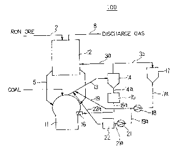
FIG. 2 illustrates an embodiment of the smelting
reduction system according to the present invention.
As shown in FIG. 2, the smelting reduction system to
which the method of the present invention is applied
includes: a melter gasifier 11 for gasifying the coal and
for melting the reduced ore; a pre-reduction furnace 12
for indirectly reducing an iron ore by utilizing the
discharge gas of the melter gasifier 11; a cyclone 14 for
receiving the discharge gas from the melter gasifier I1
through an ascending tube 13 to capture the fine iron ore
from the discharge gas so as to send it to a recycling
system 15, and for supplying the fine iron ore and the
separated discharge gas to the pre-reduction furnace 12;
a melting burner 36 installed on the melter gasifier 11,
for spouting the fine iron ore of the recycling system 15
into the melter gasifier lI; a venturi scrubber 17 for
receiving a part of the discharge gas of the cyclone 14,
to collect dust and cool it; a compressor 18 for
compressing the cooled gas of the venturi scrubber 17 so as
to supply the compressed gas through a compressed gas
circulating tube 19 to the ascending tube 13; a second
compressor 21 for recompressing a part of the compressed
gas; and a pneumatic fine ore conveying system 22 for
supplying the fine iron ore to the ascending tube 13 by
utilizing the recompressed gas of the second compressor 21.
CA 02211942 1997-08-21
WO 97/24462 PCTIKR96/00245
The melter gasifier 11 and the pre-reduction furnace
12 communicate together through a reduced ore discharge
a
tube 5. The pre-reduction furnace 12 is connected. to a
5 discharge gas discharging- tube 8, and to an iron ore
supplying tube 2 for supplying a fine iron ore.
The pre-reduction furnace 12 communicates with the
cyclone 14 through a first discharge gas circulating tube
3a. The venturi scrubber 17 communicates with the cyclone
14 through a second discharge gas circulating tube 3b.
The venturi scrubber 17 communicates with the
compressor 18 through a cooling gas circulating tube 17a.
The compressor 18 communicates with the ascending tube 13
and the second compressor 21 through a compressed gas
circulating tube 19 and a second compressed gas circulating
tube 19a respectively. The second compressor 21
communicates with the pneumatic.fine ore conveying system
22 through a third compressed gas circulating tube 21a.
The pneumatic fine ore conveying system 22 communicates
with the ascending tube 13 through a fine ore supplying
tube 22a.
The recycling system 15 communicates with the cyclone
14 through a first fine iron ore circulating tube 14a, and
is connected through a second fine iron ore circulating
tube 15a to the melting burner 16.
FIG. 3 is a detailed illustration of the pneumatic
fine ore conveying system of the smelting reduction system.
As shown in FIG. 3, the pneumatic fine iron ore
conveying system includes a raw material storing vessel
221, a lock vessel 222, a dispensing vessel 223, a raw
material dispensing feeder 224-a#~d an injector 225.
- In-the present invention, the pneumatic fine iron ore
conveying system is constituted as follows. That is, the
gas which is recompressed by the second compressor 21 is
supplied through the third gas circulating tube 21a to the
injector 225, and is supplied through a fourth compressed
CA 02211942 1997-08-21
WO 97!24462 PCT/I~t96/00245
6
gas circulating tube 227 to the lock vessel 222.
In the present invention, the pre-reduction furnace
12 pre-reduces the iron ore by utilizing the discharge gas
of the melter gasifier 11. The iron ore which has been
pre-reduced is smelt-reduced by the melter gasifier 11.
The discharge gas of the melter gasifier 11 is supplied
through the ascending tube 13 and the cyclone 14 to the
pre-reduction furnace 12. The ore fines which are
collected by the cyclone 14 are spouted through the
recycling system 15 and the melting burner 16 into the
melter gasifier 11. A part of the gas which has passed
through the cyclone 14 is supplied through the venturi
scrubber 17, the compressor I8 and the compressed gas
circulating tube I9 to the ascending tube 13. Thus the
method can be applied to the smelting reduction for
manufacturing a hot metal.
For injecting the fine iron ore according to the
present invention, a part of the gas which has passed
through the compressed gas circulating tube 19 is
recompressed by the second compressor 21, and the fine
iron ore is injected into the ascending tube 13 by means of
the pneumatic fine iron ore .conveying system 22 by
utilizing the recompressed gas. The fine iron ore which
has been injected into the ascending tube 13 is spouted
through the cyclone 14, the recycling system 15 and the
melting burner 16 into the melter gasifier 11.
In the case where the pneumatic fine iron ore
conveying system of FIG. 3 is used, the cooling reducing
gas is subjected to a pressure stepup, and then, the gas
is supplied to the lock vessel 222 and to the injector 225
installed beneath the pneumatic fine iron ore conveying
system 22. By utilizing the cooling reducing gas as the
carrying medium, the fine iron ore is injected into the
ascending tube 13 of the melter gasifier 11 under operation
with a pressure of 3.0 - 3.5 Kg/cm2. The fine iron ore thus
CA 02211942 1997-08-21
WO 97/24462 PCT/HIt96/00245
7
injected undergoes a heating and a partial reduction by
being raised by the rising gas. The fine iron ore and the
dust are separated by the cyclone 14
and th
,
en, are
supplied through the recycling system 15 and the melting
burner 16 into the melter gasifier 11
Then
b
.
car
on reacts
with oxygen which is injected by a dust burn
er, so as to
be burned. Owing to the combustion heat, the pre-reduced
fine iron ore is melted and agglomerated, so as to be
fallen down to below the melter gasifier, with the result
that it undergoes a smelting reduction, thereby producing
a hot metal.
The pressure within the ascending tube should be
preferably 3.0 - 3.5 Kg/cm2.
Further, it is desirable that the compressor 18
should compress the gas to a pressure of 3.7 - 4.2 Kg/cmz.
Further, it is desirable that the second compressor
22 should compress the gas to a pressure of 5 - 10 Kg/cm2.
For example, the discharge gas of the melter gasifier
11 is composed of 60-655 of CO, 25-30~ of H2, 3-5~ of C02
and 2-4~ of NZ.
Now the action and effect of the present invention
will be described.
The gas which is produced by the melter gasifier 11
has a high temperature of 1000-1100C
and this i
,
s
produced through the complete decomposition of a large
amount of -the tar which is the volatile material contained
in the coal. However, the optimum temperature in th
e pre-
reduction furnace 12 is 850C, ,and therefore, about 20~
of the produced reducing gas is collected by the venturi
' 30 scrubber 17 so as to cool it. Then the co
l
d
o
e
gas is
compressed by the compressor 18, and then, the compressed
gas is recirculated into the lower portion of the ascending
tube 13 of the melter gasifier 11, thereby adjusting the
temperature of the gas.
In the present invention, in order to inject the fine
8
iron ore in the smelting reducing process, a part of the
recirculated gas is collected so as to recompress it. Theu
the recompressed gas is supplied to the pneumatic fine ore
conveying system 22, so that the recompressed gas can be
used for carrying the fine iron ore into the ascending tube
13 of the smelting reducing furnace.
The carrying gas which carries the fine iron ore
should be an inert or reducing gas, so that the carrying
gas would not react with the reducing gas or the tine
particles, and that no influence would be given to the
thermal or material balance during the process. In view of
this, nitrogen may be used, but when nitrogen is used,
a separate nitrogen supplying device is required, and the
nitrogen gas is mixed with the reducing gas. If the
nitrogen content within the reducing gas exceeds about 10~,
the reducing speed is slowed in the reducing furnace.
Further, if the inert gas is used, a separate
expense is incurred as much as the gas cost.
If thc: present invention is applied to injecting the
fine iron ore in the smelting reducing process, that is,
if a part of the conventional circulating gas (which is
composed of about 65~ of CO, 25~ of H2, 5~ of COz and 3~ of
N2) is used as the carrying gas, not only there is no
variation in the amount of the total carried gas in the
ascending tube, but also there is no change in the
composition of the reducing gas supplied to the reducing
furnace. Therefore the iron ore reducing operation is
possible in a state with the existing conditions unchanged.
Further, an additional expense is not incurred.
Now the present invention will be described based on
an actual example.
A testing facility was prepared in the CORER C-2000
plant, for testing the fine iron ore operation. In the
existing COREX* c-2000 tower, there is no space for
installation of a pneumatic fine ore conveying system, and
* trademark
CA 02211942 2000-11-30
CA 02211942 1997-08-21
WO 9Tl24462 PCT/KR96/00245
9
therefore, at a distance of 10 m from the COREX main
tower, there was installed a fine iron ore carrying tower
which included a fine iron ore storing facility and a
pneumatic fine iron ore conveying system. The pneumatic
fine iron ore conveying distance consisted of a horizontal
distance of 45 m and a vertical distance of 40 m. The
pneumatic conveying condition for the fine iron ore was a
minimum pressure of 9 Kg/cmz, and this was determined in
accordance with the conveying distance. As to the carrying
gas for pneumatically carrying the fine iron ore to the
ascending tube of the melter gasifier, nitrogen having a
pressure of 11 Kg/cmz was supplied so as to reduce its
pressure to 10 Kg/cm2.
Thus the fine iron ore could be injected into the
ascending tube.
25
35