Note : Les descriptions sont présentées dans la langue officielle dans laquelle elles ont été soumises.
CA 022l33~2 l997-08-l9
,~j
P15762.SCA
PRESS SECTION AND PROCESS FOR DRAINING A WATERY FIBROUS
PULP ~H~;~; l .
CROSS-REFERENCE TO RELATED APPLICATION
The present invention claims the priority under 35 U.S.C. 119 of German
ApplicationNo.196 33 422.5 filed August 20, 1996, the disclosure of which is expressly
incorporated by reference herein in its entirety.
BACKGROUND INFORMATION
1. Field of the Invention
The present invention relates to the press section of a paper machine which
includes at least two press openings through which a watery fibrous pulp is guided,
together with at least one felt belt. The invention also relates to a process for dewatering
a watery fibrous pulp sheet, whereby the sheet is guided with the felt belt through at least
two press openings.
2. Discussion f Background Information
In the current state of the art, a watery fibrous pulp sheet, coming out of the sieve
section of a press machine, is drained in several press openings in the paper machine's
press section. For this, each fibrous pulp sheet is guided together with at least one felt
belt through a press opening. The watery fibrous pulp sheet is dewatered due to the high
pressure and force exerted in the press opening, and moisture is absorbed by the felt belt.
2 0 A separate felt belt is thereby guided for each press opening as an endless belt via
a number of felt belt guide rollers, and the felt belt is conditioned (i.e., it is dewatered)
in a conditioning device before le~ g to the press opening, where it once again
absorbs moisture upon entering the press opening. The conditioning device generally
includes a number of suction units that are operated under a high vacuum, in order to
2 5 vacuum fluid away from the felt belt to a great degree.
A disadvantage with this arrangement resides in the elaborate arrangement of thefelt belts needed for each press opening, each of which must be guided around several
deflection rollers. In addition, these felt belts have to be monitored during operation, and
from time to time they have to be replaced, which can be quite costly.
CA 022l33~2 l997-08-l9
P15762.SCA
SUMMARY OF THE INVENTION
An object of the present invention, therefore, is to provide an improved a presssection of a paper press machine, and to provide a process for dewatering a watery
fibrous pulp sheet, wherein the construction is made as simple as possible and wherein
5 operation of the press section can occur in a simplified and cost efficient manner.
The object of the present invention is accomplished in the press section of a paper
press machine by guiding a felt belt through both press openings, and by designing a
conditioning device to be interposed between the two press openings that dries the felt
belt as it passes between the two openings.
The object ofthe present invention also is accomplished by a process of guiding
the fibrous pulp sheet together with a single felt belt through both press openings, and by
conditioning (i.e., de-watering) the felt belt between the press openings.
In contrast with the current state of the art, where a felt belt is required for each
press opening, the present invention utilizes a single felt belt which is guided through two
or more sequential press openings. According to the present invention, after the felt belt
passes through a first press opening, it is separated from the paper sheet and dewatered
with the aid of a conditioning device, before it enters a second press opening.
In this manner, construction of the press section is greatly simplified, since fewer
deflection rollers are required, because the number of endless circulating felt belts is
reduced. Additionally, m~tçri~l costs are saved, since the total length ofthe felt belt sheet
will be shortened. Moreover, the costs incurred during a felt belt exchange also are
reduced, as substantially fewer felt belt exchanges have to be performed.
According to the present invention, after the felt belt exits from the second press
opening, the felt belt is again dewatered, with another conditioning device.
2 5 In a particular embodiment of the present invention, the watery fibrous pulp sheet
is guided between two press openings on a smooth press belt. This embodiment has the
advantage of ensuring a closed sheet guidance system for the fibrous pulp sheet, whereby
reverse moistening of the pulp sheet can be avoided.
In another embodiment of the invention that represents a modification of the
CA 022133~2 1997-08-19
Pl 5762.SCA
above, the felt belt is separated from the fibrous pulp sheet shortly after exiting the first
or the second press openings. In this manner, reverse moistening of the pulp sheet is
almost completely prevented. Dewatering is particularly effective, and at the same time
a closed sheet guidance system is ensured, as a result of guiding the fibrous pulp sheet
between both press openings on the smooth press belt.
According to yet another embodiment of the present invention, the fibrous pulp
sheet is guided through a smoothing press. In this manner, the characteristics of each
side of the paper sheet can be controlled or separately modified.
According to still another embodiment of the invention, the press openings
comprise shoe presses. In this way, a high degree of dehydration is achieved.
Theoretically, the shoe presses can be designed as top felt presses, or as bottom felt
presses. In the case of a top felt press, a scraper can be designed on one of the deflection
rollers over which the smooth press belt is guided to remove fibrous pulp residues.
Alternatively, where the shoe press is a bottom felt press, the scraper can be designed on
one of the deflection rollers of the smooth press belt. However, if a smoothing press is
additionally designed behind the second press opening, the scraper is preferablypositioned on the central roller of the smoothing press.
Overall, the construction of the press section according to the present invention
is designed in a simple manner and can be adjusted to fit the respective requirements.
2 0 The present invention provides a press section of a paper machine that includes
a first pair of press rollers having a first press opening therebetween, a second pair of
press rollers having a second press opening therebetween, a felt belt which is guided with
a water,v fibrous pulp sheet through the first press opening and the second press opening,
and a conditioning device which is positioned between the first press opening and the
second press opening to dewater the felt belt after it passes through the first press
opening. Dewatering the watery fibrous pulp sheet yields a fibrous pulp sheet, as the
watery fibrous pulp sheet passes through the first or second press openings. The fibrous
pulp sheet may be guided between the first and second press openings on a smooth press
belt. The felt belt also may be separated from the fibrous pulp sheet shortly after exiting
CA 022l33~2 l997-08-l9
P1 5762.SCA
the first or second press openings. The fibrous pulp sheet may further be guided through
a smoothing press, and it may be transferred to the smoothing press with the aid of a
suction roller. The first and second pairs of press rollers may be constructed as shoe
presses. The shoe presses may be designed as top felt belt presses or as bottom felt belt
presses. If the shoe presses are designed as bottom felt presses, a scraper may be placed
on the smoothing press to capture fibrous pulp residues.
The present invention also provides a process for dewatering a watery fibrous
pulp sheet in a press section of a press m~t~hin~ comprising providing a first pair of press
shoes having a first press opening therebetween, providing a second pair of press shoes
having a first press opening therebetween, guiding a felt belt and a watery fibrous pulp
sheet through the first and second press openings, and dewatering the felt belt with a
conditioning device as it is guided between the first press opening and the second press
opening.
It goes without saying that the aforementioned and following characteristic
features can be used not only in the described combinations, but also in other
combinations or alone, without leaving the scope of the invention. Further embodiments
and advantages can be seen from the detailed description and the accompanying figures.
BRIEF DESCRIPTION OF THE DRAWINGS
The present invention is further described in the detailed description which
2 0 follows, in reference to the noted drawing by way of non-limiting examples of preferred
embodiments ofthe present invention, wherein same reference numerals represent similar
parts throughout the drawings, and wherein:
Figure 1 illustrates a schematic representation of a press machine's press section
according to one aspect of the present invention; and
2 5 Figure 2 illustrates a schematic representation of a press machine's press section
according to another aspect of the present invention.
DETAILED DESCRIPTION OF THE PREFERRED EMBODIMENTS
The particulars shown herein are by way of example and for purposes of
illustrative discussion of the preferred embodiments of the present invention only and are
CA 022l33~2 l997-08-l9
P 15762.SCA
presented in the cause of providing what is believed to be the most useful and readily
understood description of the principles and conceptual aspects of the invention. In this
regard, no attempt is made to show structural details of the invention in more detail than
is necessary for the fundamental understanding of the invention, the description taken
5 with the drawings making apparent to those skilled in the art how the several forms of
the invention may be embodied in practice.
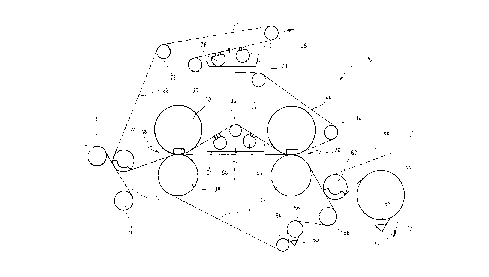
According to the present invention, the press section in Figure 1 is referenced as
a whole with the number 10. In press section 10, a watery fibrous pulp sheet 72 is passed
on
o sieve belt 12 from a preceding sieve section. Sieve belt 12 is guided over sieve guide
rollers 14, 16. With the aid of a vacuum-assisted transfer/uptake roller 24, the watery
fibrous pulp sheet 72 is transferred to an endless circulating felt belt 22 and through a
first press opening 18. Press opening 18 is created by a top-mounted shoe press roller 40
and a bottom-mounted mating roller 38. Around the mating roller 38, a smooth press belt
15 52 is guided which is also guided around the mating roller 42 of a subsequent second
press opening 20, with a top-mounted shoe press roller 44. The fibrous pulp sheet is
guided over a number of deflection rollers 54, 56, 58.
Between the two press openings 18, 20, immediately after leaving the first pressopening 18, felt belt 22 is guided away from fibrous pulp sheet 72 with the aid of a
20 deflection roller 36. At this time, fibrous pulp sheet 72 adheres to smooth press belt 52
and reaches the following press opening 20 on the smooth press belt 52.
By immediately separating felt belt 22 from the fibrous pulp sheet 72 after leaving
the first press opening 18, reverse moistening of sheet 72 is prevented.
Felt belt 22 reaches the second press opening by traveling over the deflection
25 roller 36. Felt belt 22 is dewatered by conditioning device 46 ,which is positioned
between the two press openings 18, 20. The conditioning device 46 consists of two
vacuum units 48, 50, by which moisture taken up in the first press opening 18, is largely
vacuumed off, captured in a trough 51, and removed to the outside.
- After passing through the second press opening 20, the fibrous pulp sheet 72
CA 022133~2 1997-08-19
P15762.SCA
remains adhered to the smooth press belt 52 as it is guided down with the aid of a
deflection roller 58. Felt belt 22 is immediately carried up and over felt guide roller 34,
after passing through the second press opening 20, in order to prevent reverse moistening
of the pulp sheet.
The felt belt 22 is guided further along over additional felt belt guide rollers 26,
28, 30, 32, and felt belt 22 is dewatered in a second conditioning device 74 with the aid
of two vacuum units 76, 78, whereby the water is captured in a trough 79 and removed
to the outside.
Afterwards, the fibrous pulp sheet 72 is transferred from the smooth press belt 52
with the aid of a suction roller 62. The fibrous pulp sheet 72 is guided on a drying sieve
belt 66 to a subsequent drying section, of which only the first drying cylinder 64 is
displayed. Drying sieve belt 66 feeds around drying cylinder 64, which then reaches the
subsequent drying cylinders of the drying section in the direction of the arrow 70.
Fibrous pulp residues are removed from the smooth belt 52 in the bottom section
of the press section with the aid of a scraper 60 that mounts to a deflection roller 56, and
over which the smooth, soft press belt 52 is guided. The drying cylinder 64 likewise is
equipped with a scraper 68 to scrape off the fibrous pulp residues.
Another embodiment of the present invention is described in Figure 2. It consists
of two shoe presses 38a, 40a, 42a, 44a, but in contrast to the embodiment in Figure 1,
2 o it is constructed as a bottom-felt belt press.
In Figure 2, the fibrous pulp sheet 72 is passed on a sieve belt 12 that is guided
in a preceding sieve section over sieve guide rollers 14, 16. With the aid of a smooth
transfer/uptake roller 24a and moisturizing elements 84, 86, the fibrous pulp sheet 72 is
transferred to an endless, smooth press belt 52a. Fibrous pulp sheet 72 passes to the first
2 5 press opening 18, that is created by a bottom-mounted shoe press roller 38a and a top-
mounted mating roller 40a.
A felt belt 22a, guided by guide rollers 26a, 28a, 30a, 32a, 34a, and 36, also is
guided through the first press opening 18. The felt belt subsequently passes through a
second press opening 20 after being deflecting over felt belt guide roller 36.
CA 022l33~2 l997-08-l9
P 15762.SCA
After passing through the first press opening 18, the felt belt 22a is drained in a
conditioning device 46a which is positioned between the first and second press openings
with the aid of vacuum units 48a, 50a. The drained fluid is captured in a trough 51 a and
removed. After passing through the second press opening 20, the felt belt 22a is5 deflected over felt belt guide rollers 34a, 32a, and felt belt 22a is dewatered in a second
conditioning device 74a, with the aid of vacuum units 76a, 78a. The drained fluid is
captured in trough 74a and removed. Before felt belt 22a returns to the first press
opening 18, it is guided over additional felt belt guide rollers 30a, 28a, 26a.
By draining felt belt 22a with the aid of the first conditioning device 46a shortly
10 before enter1ng the second press opening 20, a particularly effective drying of the felt belt
occurs, and therefore a high water absorption capability is achieved in the second press
opening.
After passing through the first press opening 18, the fibrous pulp sheet 72 is
guided to the second press opening 20 on smooth press belt 52a, while the felt belt 22a,
15 after exiting press opening 18, is immediately separated from the fibrous pulp sheet 72
in order to prevent reverse moistening.
Felt belt 22a is separated from the fibrous pulp sheet 72 immediately after exiting
the second press opening 20. The fibrous pulp sheet is guided by belt 52a to smoothing
press rollers 80, 82, so that reverse moistening is prevented here as well. Smoothing
2 o press rollers 80, 82 also serve to control or modify the characteristics of each side of the
manufactured paper sheet, in accordance with respective requirements.
Fibrous pulp residues are taken off smoothing press roller 82 with the aid of
scraper 60a. The fibrous pulp sheet 72 is transferred from smoothing press roller 82, with
the aid of a suction roller 62, onto drying sieve belt 66, and it is guided over the first
25 drying cylinder 64 of a subsequent drying section. Fibrous pulp residues are again
removed with the aid of a scraper 68.
According to the present invention, it is understood that the common felt belt can
be guided through two or more press opening, provided that the felt belt is dewatered
between each of the press openings.
CA 022133~2 1997-08-19
P1 5762.SCA
It is noted that the foregoing examples have been provided merely for the purpose
of explanation and are in no way to be construed as limiting of the present invention.
While the invention has been described with reference to a preferred embodiment, it is
understood that the words which have been used herein are words of description and
5 illustration, rather than words of limitation. Changes may be made, within the purview
of the appended claims, as presently stated and as amended, without departing from the
scope and spirit of the invention in its aspects. Although the invention has been
described herein with reference to particular materials and embodiments, the invention
is not intended to be limited to the particulars disclosed herein; rather, the invention
10 extends to a functionally equivalent structures, methods and uses, such as are within the
scope of the appended claims.