Note : Les descriptions sont présentées dans la langue officielle dans laquelle elles ont été soumises.
CA 02213~32 1997-08-22
W O 96/27922 PCTIGB96/OOS38
ELECTRICAL CO~NEC~OR
The present invention relates to electrical
connectors, particularly althou~h not exclusively to an
electrical connector for connect:ion to a printed circuit
board.
According to one aspect of the present invention
there is provided a board mountable elecl~rical socket
comprising:
a socket base; and
a socket head,
- wherein the socket head comprises locking means for
locking the socket head to the board, the arrangement
being that in use, the socket base is securec3L to the board
by placing the socket base between the socket head and the
board, and locking the socket head to the board.
Suitably, the socket is adapted for fitment to a
printed circuit board.
Preferably, the socket base comprises means for
seating the base in an aperture in the boartiL. Preferably
said seating means comprises a rim extending around an
upper end of the base.
Preferably, the socket base is adapted for receiving
a first plurality of electrical connectors.
Preferably, said base is provided with a plurality of
passages extending through the base, each said passage
arranged for receiving a said electrical connector.
CA 02213~32 1997-08-22
W 096/27922 PCT/~-"~ 8
Preferably a said electrical connector comprises a
connector pin, preferably a female connector pin.
Said connector pin may comprise a crimp connector.
Preferably, a said passage is arranged such that a
said electrical connector pin may be inserted into the
passage from a lower end of said passage, and pushed
through said passage, so as to partially protrude from an
upper end of said passage, a portion of said electrical
connector pin remaining in said passage.
Preferably, said passage is surrounded or partially
surrounded by a pin seating portion. The pin seating
portion is preferably arranged around a periphery of said
passage such that said pin seating portion may expand when
a said electrical connector pin passes through said
passage in a first direction, and may contract thereafter,
thereby preventing passage of said electrical connector
pin in a second direction, opposite to said first
direction.
Preferably, a said pin seating portion comprises a
substantially tubular portion surrounding said passage.
Preferably said socket head comprises a substantially
tubular member having a lower end arranged to engage said
socket base portion, said lower end being provided with
said locking means for locking the lower end of said
socket head to a board.
Preferably, in use, where the socket is to be fitted
to a board, for example a printed circuit board, an
aperture is formed in the printed circuit board the
aperture having a periphery of a shape which closely fits
CA 02213~32 1997-08-22
W O 96/27922 PCT/GB96/00538
the base, such that the base may be inserted through the
aperture from a position at an upper side of the board,
the base being prevented from passing completely through
the aperture by the seating rim at the uppe:r end of the
base, the seating rim arranged to locate around the
periphery of the aperture. The head is placed over the
base, and the locking means are inserted bet~een the base
and the periphery of the aperture, such that the locking
means extend to a position on a ]Lower side of the board.
The locking means may then engage the periphery of the
aperture on the lower side of the board, such that the
locking means can lock the lower end of the head to the
board, the base being secured between the head and the
board.
The invention includes a method of attaching a socket
to a board, the method comprising the steps of:
forming an aperture in the board;
inserting a socket base from a position at an upper
side of the board, through the! aperture such that a
portion of the socket base projects through the aperture
and extends beyond a lower side of the board
presenting a socket head at a position at an upper
side of the board, and engaging said socket head with said
board, such that a portion of said socket head passes
through said aperture between a pe!riphery of said aperture
and said base, and engages the board, such that a portion
of said base is secured to the board on the upper side of
the board, between said head and said upper side.
Preferably, said locking means comprise first and
second arms extending from said lower end of the socket
CA 02213~32 1997-08-22
W 096/27922 PCT/~~5/v0~38
head. A said arm preferably comprises a tapered portion,
tapered in a direction substantially along a main length
of the socket head.
Preferably, said first and second arms are each
provided with a said tapered portion, first and second
arms capable of initially adopting a first position in
which said first and second arms are spaced apart from
each other by a first distance, and the arms being
deformable when passing through a said aperture, such that
the first and second arms move towards each other, and
thereafter, once said first and second arms are inserted
into the aperture, said first and second arms may return
substantially to said first position, by moving away from
each other.
-
Preferably said tapered portions are arranged toengage an underside of said board when socket head is
engaged with said board.
Preferably said socket head comprises first and
second housing portions contained within said tubular
member, said first and second housing portions surrounding
respective first and second cavities. Preferably, said
electrical connector pins are arranged to be a close fit
within said corresponding first and second cavities.
Preferably, an upper end of said tubular member
extends beyond an upper end of a said housing, by a
distance in the range 5-2omm, and preferably at least
11.5mm.
Preferably, a crimp portion of a said female
connector pin, is completely contained within a said
passage in said base in use.
CA 02213~32 1997-08-22
W ~96127922 P ~/GB96/00538
Preferably, said socket head is provided at a lower
end thereof, with a downwardly pr~jecting locating lug for
locating with said socket base. Preferably said locating
lug is provided with a skirt port:ion for surrounding said
pin seating portions.
Preferably said tubular member is provided on an
internal surface thereof with an elongate spline ext~n~;ng
in a direction parallel to a ma:in length of the tubular
member.
According to a second aspect of the present
invention, there is provided a plug for an electrical
cable, said plug comprising a cap portion s~lrrounding an
end of said cable;
a plurality of electrical c:onnector pins, one said
connector pin being electrically bonded to an earth
conductor of said cable and another said electrical
connector pin being connected with a signal conductor of
said cable;
the arrangement being that said pins extend in a
direction transverse to a main length of said cable, said
pins being surrounded by an insulating tubular sheath
which extends beyond a lower extremity of sa:id pins, in a
direction transverse to said main length of cable.
Preferably, said sheath e!xtends beyond a lower
extremity of a connector pin, by a distance in the range
3-lOmm, and preferably at least 6.5mm.
Preferably, said plug is formed of an inner portion
which is formed in a first forming operation, and an outer
portion which is formed in a second forming operation.
CA 02213~32 1997-08-22
W 096/27922 ' PCT/~-''~0538
Preferably said first and second forming operations
comprise moulding operations. Preferably said plug
comprises a nylon moulding.
,~
Preferably an outer surface of said sheath is
provided with a channel for engaging a said spline of the
socket head, the arrangement being that the spline of the
socket head engages the channel on the sheath, thereby
ensuring that a first male connector pin engages a first
female connector pin and a second male connector pin
engages a second female connector pin.
For a better understanding of the invention, and to
show how embodiments of the same may be carried into
effect, reference will now be made, by way of example, to
= the accompanying diagrammatic drawings, in which:
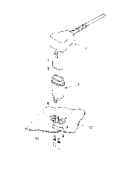
Figure 1 shows in cut away view from the side, a
socket according to a first specific embodiment of the
present invention, engaged with a printed circuit board;
Figure 2 shows in exploded view an assembly of the
socket of figure 1, with the plug and the printed circuit
board;
Figures 3 to 6 show respectively in under side view,
plan view, side view, and cut away end view a base of the
socket;
Figure 7 shows in expanded view a pin seating portion
of the base;
Figure 8 shows in perspective view a female pin
connector comprising the base;
CA 02213~32 1997-08-22
W 096/27922 PCT/~,~'~C-~
-- 7
Figure 9 shows in cut away end view a head portion of
the socket;
Figure 10 shows in expanded view a lock.ing portion of
the socket head;
Figure 11 shows in expanded view a deta.il of an upper
end of the socket head;
Figure 12 shows in side vie'w the socke1- head;
Figure 13 shows in plan v.iew the soc]~et head, and
figure 13a shows in expanded view a portion of an upper
end of the socket head;
1~
Figure 14 shows in cut away side view the socket
head;
Figure 15 shows in cut away side view a plug
according to a second specific embodiment of the present
invention;
Figure 16 shows in end view the plug of figure 15;
Figure 17 shows in plan view the plug of figure 15;
and
Figure 18 shows from an underside, the plug of figure
15.
Referring to figures 1 to 17 of the accompanying
drawings, and initially to figures 1 and 2, a plug and
socket assembly for fitment to a printed circuit boar~
comprises a socket base 1, a socket head 2, and a plug 3.
3S
CA 02213~32 1997-08-22
W 096/27922 PCT/~5~1Q~8
Referring to figures 3 to 8 of the accompanying
drawings, there will now be described the socket base.
The socket base comprises for example a nylon base
moulding 10 having a base width a, a base length b and a
base height c, an upper end of the base having a
peripheral seating rim 11, extending around a perimeter of
the base, and the base being provided with first and
second passages 12, 13 each arranged for receiving a
corresponding first or second female electrical connector
pin, 20 as shown in figure 8. The passages 12, 13 have a
main length which extends in a direction transverse, and
in particular perpendicular, to a plane defining a seating
surface 15 on a lower side of the seating rim 11. The
passages extend between an upper end of the base and a
lower end of the base. The passages comprise a first
substantially cylindrical section 16, and a second,
substantially frusto conical section 17, as shown
particularly in figures 5, 6 and 7. At the upper end of
each passage is provided a pin seating portion 19. The
pin seating portion in the form of a first and second
arcuate walls 21, 22 respectively defining the frusto
conical section 17 of the passage. The first and second
walls 21, 22 are separated from each other such that they
face opposite sides of the passage. The first and second
walls are deformable from, and normally return to their
frusto conical shape, in which they are originally formed.
The electrical connector pin 20 comprises a female
crimp pin formed by rolling a sheet of resilient metal
into a tubular form, to provide a female socket portion
30, and at an upper end of the pin and a crimp portion 31
at a lower end of the pin. Between the female socket
portion and the crimp portion is provided a protruding
ring portion 32, of diameter larger than the diameter of
the female socket portion.
CA 02213~32 1997-08-22
W 096127922 PCT/GB96/00538
In use, the female pin may be inserted into a said
passage 12 or 13 in the base, by inserting the female
socket portion 30 of the pin at: an upper end of the pin
into a lower end of the passage 12 or 13 at the lower end
of the base, and pushing the pirl in a direcltion along the
passage towards the pin seating portion 19, such that the
female socket portion 30 of the]?in passes t]hrough the pin
seating portion, splaying the fi.rst and second side walls
21, 22 of the pin portion apart as the ring portion 32
passes through the pin seating portion, the pin seating
portion then contracting, as the ring porti.on passes out
of the upper end of the passage, such that t:he electrical
pin seats on top of the pin seating portion. 19, the ring
32 resting on top of the ring seating portion and
preventing the pin from being drawn back int:o the passage
in a direction from the upper encl of the base to the lower
end of the base. The crimp portion 31 rema.ins contained
within the cylindrical portion ~.6 of the passage. Since
the crimp portion 31 is crimped a.round an electrical wire,
and may be soldered to the electrical wire, when the pin
20 is inserted into the passage 12 or 13, and passed out
of the upper end of the passage, so that the ring portion
passes through the seating porti.on 19, if the pin passes
too far through the passage, the pin may be withdrawn back
towards the passage by pulling t:he wire con:nected to the
crimping portion 31, such that the ring 32 seats on an
upper periphery of the seating portion 19.
Referring to figures 9 to 13 of the accompanying
drawings, there is shown the socket head :2. The head
comprises an insulating tubular wall 30 moulded from, from
example nylon, the tubular wall closed at a lower end 31
thereof by a floor portion 32 which extend.s across the
lower end of the tubular portion 30, the tubular portion
having a substantially oval cros~; section, t]he oval cross
CA 02213~32 1997-08-22
W 096127922 PCTI~,"~Q5~8
-- 10 --
section comprising first and second semi circles spaced
apart and placed oppositely from each other and separated
by a linear portion extending between said first and
second semi circles, as shown in plan view in particular
in figure 13; the lower end 31 of the socket head being
provided with first and second locking portions 34, 35
respectively each locking portion comprising an extending
arm of a first thickness, having a foot portion of a
second, larger thickness, the foot portion comprising a
tapered portion, becoming thicker towards a lower
extremity of the foot portion 36, the tapered portion as
viewed in cross section forming a wedge, the wedge having
a lower point extending in a direction along a main length
of the head and facing outwardly away from the tubular
body; internally of the tubular body are provided first
and second substantially cylindrical pin housings 37, 38
each having a central cavity 39, 40 respectively for
receiving a female socket portion of a respective said
connector pin, the tubular member additionally being
provided on one side, with an elongate spline 41 ext~n~;ng
along the length of the head and internally of the tubular
member, as shown particularly with reference to figure
13a, for ensuring that the plug is fitted into the socket
in a predetermined manner such that connection is made to
the first and second female pins in the correct electrical
polarity.
Referring to figures 15 to 18 respectively, there is
shown the plug. The plug is moulded around an end of a
conventional coaxial cable 50 having an outer sheath 51
surrounding concentrically an earth shielding, and
contained within the earth shielding an insulator portion
53 surrounding concentrically a central conductor 54. The
plug comprises a moulded cap portion 55 the cap portion
being moulded in two parts being a first, inner moulded
CA 02213~32 1997-08-22
W 096/27922 PCT/GB96/00538
part 54, which is moulded around the end oi- the coaxial
cable, and a second, outer moulded part 57 which is
moulded around the inner moulded part. The outer moulded
part includes an elongate tubular sheath 5'3 surrounding
first and second substantially cylindrical cavities 60, 61
respectively. Concentrically with each cavity are
provided a first and second male connector pin, the first
male connector pin being electrically connected with the
inner conductor 54 of the coaxia]L cable prior to moulding
the cap, and the second male pin being electrically
connected with the earthing sheath of the coaxial cable,
prior to moulding the head. The ltubular sheath 59 extends
in a direction perpendicular to a main axis of the coaxial
cable, such that connection of a coaxial cable to a
printed circuit board may be made with the coaxial cable
extending substantially parallel to a main plane of the
printed circuit board, when the plug is inserted in the
socket as previously described here above. i~dditionally,
the tubular sheath 59 is formed having a channel 63
positioned between the first and second male pins, the
channel 63 arranged to engage with the spline 41 of the
socket head, to ensure that the first and second male pins
engage the respective first and second female pins, and
that the plug cannot be inserted into the head of the
socket the wrong way engaging the second male pin with the
first female pin. This ensures that the earth shielding
of the coaxial cable is connec:ted to a corresponding
earthed female pin of the socket.
Fitment of the socket to a printed circuit board will
now be described with reference to figures 1 to 18 of the
accompanying drawings.
Referring in particular to figures 1 and 2, an
aperture 80 is formed in a print~ed circuit board 81, the
CA 02213~32 1997-08-22
W 096/27922 PCT/~b~ 538
aperture being of dimension such that it closely fits
around a perimeter of the base 1. The base is dropped or
meçh~n;cally placed into the aperture in a direction from
above the circuit board, such that the base protrudes
through the circuit board, but is prevented from passing
completely through the circuit board by the seating rim 11
which sits on the upper surface of the board around the
perimeter of the upper end of the base. The socket head
is then aligned such that the lower locating lug 45 of the
head portion locates within the seating rim 11 of the
base, the locking arms 34, 35 respectively on either side
of the head, being inserted between the base and the PCB,
and through the aperture 80 in the printed circuit board,
such that the tapered portions 34, 35 of the locking arms
extend through the aperture and to a position below an
underside of the printed circuit board. In this position,
the locking arms, which are urged slightly towards each
other when passing through the aperture, may expand away
from each other their original configuration as formed,
thus causing the thicker end of the tapered wedge portions
to contact the underside of the printed circuit board at
the periphery of the aperture 80, thereby preventing the
tapered portions from returning back through the aperture,
and thereby locking the lower end of the head to the PCB.
Since the base is positioned between the head portion and
the PCB, but is prevented from passing through the PCB by
virtue of the seating rim 11, the locking arms lock the
head portion and the base portion of the socket to the
PCB.
once the base and head are located to the PCB, the
first and second female pin connectors may be passed from
underneath the PCB, through the lower end of the passages
12, 13 in the base of the socket and, such that the ring
31 on the female pin passes through the pin seating 19,
CA 022l3~32 l997-08-22
W 096127922 P ~'5G/~53
- 13 -
through which it cannot return, the female crimp portion
of the female pin being housed ~7ithin the pin housing 40
of the head portion.
The plug 3 may then be inserted into the head of the
socket, and pushed down such that:the male pins engage the
corresponding respective female pin connectors to make
firm mech~nical and electrical contact between the plug
and socket, thereby ensuring firm electrical and
mechanical contact between the coaxial c;~ble and the
printed circuit board.
The provision of the loc:king arms 34, 35, the
guidance spline 41 and corresponding channel in the plug
sheath, and the protrusion 70 on the outer surface of the
pin sheath, ensures a snap fit b,etween the base, head and
plug.
As shown in figure 1, the plug and socket may be
contained within a casing 100, the casing having an
aperture 101 through which the upper end of the head may
pass, the casing locating on an upper peripheral seating
rim 102 formed around an outer surface of the tubular
portion of the head. An upper end of the head is arranged
to be flush with the outer surface of the cas ing.
In use, the outer surface of the casing is accessible
to a person and since the first and second female pins are
provided within the tubular s~cket head, in the pin
housings, and the pin housings and female pins are
positioned at a depth of at least 11.5mm from the upper
end of the socket head, a user is protected from
accidentally contacting the female pins when the plug is
not connected. Further, since the male pins are enclosed
within the insulating sheath 59 of the plug, there being
CA 02213~32 1997-08-22
WO 96/27922 PCrl~D~ Q~5~8
-- 14 --
a distance of at least 6.5mm between the tip of the male
pins and the lower end of the sheath, the chances of
accidentally contacting the male pins and thereby
incurring electric shock, are reduced.
Specific embodiments of the present invention may
have an advantage of providing a socket which can be
quickly and easily fitted to a printed circuit board from
a position above the printed circuit board, and which is
suitable for automated connection of the socket to the
printed circuit board.
Further, specific embodiments may provide an
advantage of providing a socket which is physically
shielded, having pins protected from accidental contact
due to the inaccessibility of the female pins from a
position outside the socket, for anything except the
matching plug.
The reader's attention is directed to all papers and
documents which are filed concurrently with or previous to
this specification in connection with this application and
which are open to public inspection with this
specification, and the contents of all such papers and
documents are incorporated herein by reference.
All of the features disclosed in this specification
(including any accompanying claims, abstract and
drawings), and/or all of the steps of any method or
process so disclosed, may be combined in any combination,
except combinations where at least some of such features
and/or steps are mutually exclusive.
Each feature disclosed in this specification
(including any accompanying claims abstract and
CA 02213532 1997-08-22
W ~96~27922 PCT/~D~/0
- 15 -
drawings), may be replaced by alt:ernative features serving
the same, equivalent or similar purpose, un]ess expressly
stated otherwise. Thus, unless expressly stated
otherwise, each feature disclosed is one example only of
a generic series of equivalent or similar features.
The invention is not restricted to the details of the
foregoing embodiment(s). The invention extends to any
novel one, or any novel combination, of the features
disclosed in this specification (including any
accompanying claims, abstract a~nd drawings), or to any
novel one, or any novel combinat:ion, of the steps of any
method or process so disclosed.
-