Note : Les descriptions sont présentées dans la langue officielle dans laquelle elles ont été soumises.
CA 02213816 1997-08-26
-1-
DESCRIPTION
PROCESS AND APPARATUS FOR MANUFACTURING
A FOAMED RESIN CONTAINER WITH A LABEL
TECHNICAL FIELD
The present invention relates to a process and apparatus
for producing a foamed resin container with a label for use as
a bowl for instant noodles, a drinking cup for juice, hot
coffee or the like, a vessel for frozen sweets, or a like
packaging container.
BACKGROUND ART
Conventionally, foamed resin containers have widely been
used as vessels for instant food, juice or the like. Such a
foamed resin container is generally produced through a foam
molding method in which pre-foamed beads obtained by
preliminarily foaming foamable resin beads containing a
polystyrene resin and a volatile blowing agent such as butane,
pentane or chrolofluorocarbon are loaded in a mold cavity and
heated by a heating medium such as steam for foaming the
foamed resin containers.
Some of the foamed resin containers are provided with a
label which bears information such as a trade name and a
maker's name and/or a design such as a vignette printed
thereon, or serves to impart an excellent gas barrier property
to the foamed resin containers.
CA 02213816 1997-08-26
-2-
Known as a method for providing such information or the
like on the surface of a foamed resin container (foamed bead
cup), there are a method wherein information or the like is
directly printed on the surface of a foamed resin container, a
method wherein a label bearing information or the like
preliminarily printed thereon is bonded onto a foamed resin
container, and a so-called shrink-labeling method wherein a
heat-shrinkable film bearing information or the like
preliminarily printed thereon is wrapped around a foamed resin
container and shrunken by heat.
In the method of directly printing on the surface of a
foamed resin container, it is difficult to obtain a sharp
printing like gravure or to perform a multi-color printing.
In the method of bonding onto a foamed resin container a label
bearing information preliminarily printed thereon, a container
molding step, a label stamping step, and a label bonding step
are separately performed. Therefore, it is required that the
label be positioned in place in the label bonding step, so
that the process is complicated. In the shrink labeling
method using a heat-shrinkable film, the heat-shrinkable film
softly adheres on the container so that the film is liable to
slip out of the container if the container has an inclined
circumferential surface.
To solve these problems, Japanese Unexamined Patent
Publication No. 4-331132 (1992) discloses a method for in-mold
CA 02213816 1997-08-26
-3-
labeling of a foamed resin container, which includes steps of
rolling into a predetermined tubular shape a print paper sheet
having a print layer on the outer surface and a heat-seal
layer on the inner surface of a paper base, setting the print
sheet in a cavity mold, fixing the print sheet on the inner
wall of the cavity mold by evacuating the cavity through a
multiplicity of gas vent holes provided in the cavity mold,
matching the cavity mold with a core mold, loading foamable
resin beads into a gap defined between the print paper sheet
and the core mold for foam molding, and fuse-bonding the print
paper sheet onto the resulting foamed resin container by
applying heat thereto for the foamed resin molding.
However, the aforesaid method involves complicated
process steps because the print paper sheet is once punched
out into a predetermined configuration and then the punched
sheet should be rolled into a tubular shape. Further, the
print paper sheet which has the print layer and the heat-seal
layer provided, respectively on the opposite surfaces of the
paper base is inferior in the moisture resistance and gas-
barrier property. Therefore, the paper sheet absorbs steam
applied when the foamed resin container is molded, so that the
printing is liable to be blurred. In addition, because the
print layer on the outer surface of the paper base is brought
in directly contact with the cavity mold, the printing ink is
liable to be transferred onto the cavity mold from the print
CA 02213816 1997-08-26
-4-
paper sheet by heat. If the printing ink transfer occurs, the
print density on the foamed resin container is reduced,
resulting in a printing failure. The ink transferred onto the
cavity mold is further transferred onto the next mold product,
resulting in successive printing failures.
Since the print paper sheet should be rolled into a
tubular shape before the molding, the process steps are
complicated, resulting in an increased cost.
To solve these problems of the prior art, it is an object
of the present invention to provide a novel process and
apparatus for producing a labeled foamed resin container with
which employ a thin and less stiff or floppy synthetic resin
sheet instead of the paper base and a label obtained by
preliminarily printing fine letters and a sharp design such as
including smooth gradation on the resin sheet, and is adapted
to apply the floppy sheet label in a predetermined position on
the foamed resin container by integral molding without rolling
the label into a tubular shape before molding the foamed resin
container.
It is a more specific object of the present invention to
provide a process and apparatus for producing a foamed resin
container with a label, in which a sheet which bears printed
labels in predetermined portions thereof is continuously
supplied and a process sequence from the step of punching a
label from the sheet to the step of molding the foamed resin
CA 02213816 1997-08-26
-5-
container with a label is readily and continuously performed.
DISCLOSURE OF INVENTION
In accordance with one preferred mode of the present
invention to achieve the aforesaid objects, there is provided
a process for producing a foamed resin container with a label
provided on a circumferential surface thereof by integral
molding, comprising steps of:
supplying a continuous sheet which bears label bodies
printed thereon to a label punching device upon positioning
each of the label bodies at a punching position;
cutting off the label body and fixing a resulting label
on a label reception platform having means for fixing the
label beneath the punching position;
moving the label reception platform which bears the label
fixed thereon to supply the label to a predetermined position
with respect to a dummy core mold;
applying pressurized gas jet to the label to wind the
label around the dummy core mold while fixing the label around
the dummy core mold by suction through vent holes formed in
the dummy core mold;
matching the dummy core mold which bears the label fixed
thereon with a cavity mold, and then transferring and fixing
the label onto an inner wall of the cavity mold in intimate
contact therewith by stopping the suction from the dummy core
mold or by pressurizing through the vent holes of the dummy
CA 02213816 1997-08-26
-6-
core mold while sucking through vent holes formed in the
cavity mold;
separating the dummy core mold from the cavity mold which
bears the label fixed on the cavity inner wall in intimate
contact therewith; and
locking a core mold with the cavity mold, loading
foamable resin beads therebetween, and heating the foamable
resin beads for foam molding, whereby the foamed resin
container is molded integrally with the label.
In accordance with another preferred mode of the present
invention, there is provided an apparatus for producing a
foamed resin container with a label provided on a
circumferential surface thereof by automatically performing a
process sequence from a label punching step to an integral
molding step, comprising:
a sheet feeding device having a mechanism which is
capable of positioning each of label bodies printed on a
continuous sheet;
a label punching device which includes a punching
mechanism for punching the supplied sheet in order to obtain a
label in a predetermined configuration, and a label reception
platform adapted to fix the label thereon at a position where
the label has been punched and to be movable to a
predetermined position with respect to a dummy core mold;
a device for winding up the sheet after the punching of
CA 02213816 1997-08-26
_7_
the label;
a cavity mold provided in association with the dummy core
mold so that the cavity mold can be matched with the dummy
core mold, the dummy core mold having vent holes for suction
to fix the label around the dummy core mold after the label is
wound around the dummy core mold by a pressurized gas jet
mechanism; and
a core mold provided in association with the cavity mold
so that the cavity mold can be matched with the core, the core
mold having suction holes for intimately fixing the label
thereon by sucking the label after the label is transferred
from the dummy core mold onto an inner wall of the cavity
mold, a feed hole for feeding foamable resin beads, and heater
means for foam molding, the cavity mold having heater means
for the foam molding.
In accordance with the present invention, a continuous
sheet which bears label bodies printed in predetermined
portions thereof is supplied so that each of the label bodies
can be properly positioned, and then the label body is cut off
and transported to the predetermined position with respect to
the dummy core mold by the label reception platform which has
the means for fixing the label to that position. Therefore,
only one positioning operation is required before the label
punching, and no subsequent positioning operation is required.
Further, since the label such as of a synthetic resin wound
CA 02213816 1997-08-26
_g_
around the dummy core mold is held around the dummy core mold
by suction through the vent holes, there is no need to
preliminarily roll the label into a tubular shape.
Therefore, the foamed resin container with a label
provided in a predetermined position on the circumferential
surface of the container in an integral manner can be produced
readily and efficiently. Further, the step of rolling the
label into a tubular shape can be eliminated, so that the
apparatus can be simplified, requiring no complicated process
and no special device.
In the production apparatus, the label punching mechanism
includes a punching plate for cutting off the label from the
sheet which bears the label bodies printed thereon and then
holding the label, the punching plate being formed with an
opening having a configuration compatible with the label, and
the label reception platform is adapted to move up through the
opening to the upper side of the punching plate and have vent
holes for pressurization and suction.
With this arrangement, the label thus cut off and held on
the punching plate is transported, as it is, to the dummy core
mold and therefore, the position of the label once determined
is not changed.
In accordance with another preferred mode of the present
invention, there is provided a process for producing a foamed
resin container with a synthetic resin label provided on a
CA 02213816 1997-08-26
-9-
circumferential surface thereof by integral molding,
comprising steps of:
winding the label around a dummy core mold, and retaining
the label around the dummy core mold by suction through vent
holes formed in the dummy core mold;
correcting a possible positional offset of the label by
stopping the suction from the dummy core mold immediately
before the dummy core mold retaining the label is matched with
a cavity mold, or by matching the dummy core mold with the
cavity mold;
transferring the label onto a cavity inner wall of the
cavity mold and fixing the label thereto in intimate contact
therewith by pressurizing the label through the vent holes of
the dummy core mold;
separating the dummy core mold from the cavity mold with
the label fixed onto the cavity inner wall in intimate contact
therewith; and
locking the cavity mold with a core mold with the label
fixed onto the cavity inner wall in intimate contact
therewith, then loading foamable resin beads, and heating the
foamable resin beads for foam molding, whereby the foamed
resin container is molded integrally with the label.
In accordance with the present invention, the suction
from the dummy core mold is stopped immediately before the
dummy core mold holding the label thereon is matched with the
CA 02213816 1997-08-26
-10-
cavity mold to correct the positional offset of the label by
the matching of the dummy core mold with the cavity mold.
Even if the positional offset of the label occurs, the label
wound around the dummy core mold is once freed and therefore,
when the dummy core mold is matched with the cavity mold, the
positional offset of the label is corrected. Then, the label
is transferred onto a predetermined position of the inner wall
of the cavity mold and fixed thereon in intimate contact
therewith by pressurizing the label through the vent holes of
the dummy core mold in the subsequent step.
Thereafter, the cavity mold is locked with the core mold
with the label fixed onto the cavity inner wall in intimate
contact therewith. Then, the foamable resin beads are loaded
and heated for foam molding, whereby the foamed resin
container can be molded integrally with the label. Therefore,
the foam molding of the foamed resin container and the
application of the label are simultaneously achieved while the
positional offset of the label is efficiently prevented
without rolling the label into a tubular shape before the foam
molding.
Thus, the foamed resin container with the synthetic resin
label provided on the circumferential surface thereof can be
produced efficiently through a simplified process by employing
a thin and less stiff synthetic resin sheet, instead of a
paper base, and a label bearing fine letters and a sharp
CA 02213816 1997-08-26
-11-
design such as including smooth gradation preliminarily
printed thereon and by providing the label in a predetermined
position on the foamed resin container in an integral manner
while efficiently preventing the positional offset of the
label.
The resulting foamed resin container with a label is
aesthetic, and the label is flush with the circumferential
surface of the resulting foamed resin container, and is less
liable to be peeled off. Therefore, the foamed resin
container can readily be produced which has a label bearing
information represented by fine letters and a sharp design
such as including smooth gradation printed thereon by multi-
color printing or the like.
HRIEF DESCRIPTION OF DRAWINGS
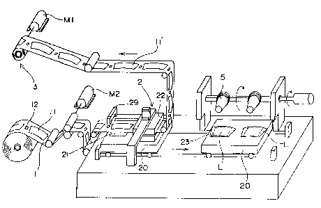
Fig. 1 is a schematic view illustrating 'an apparatus
adapted to supply a sheet including label bodies printed in
predetermined positions thereon, stamp out a label body out of
the sheet and transport the resulting label in accordance with
one embodiment of the present invention;
Fig. 2 is a front view illustrating a sheet which bears a
label body in a predetermined position thereof;
Fig. 3 is a sectional view illustrating a punching
device;
Figs. 4(1) to 4(3) are diagrams for explaining the step
of winding a label around a dummy core mold;
CA 02213816 1997-08-26
-12-
Fig. 5 is a perspective view illustrating a label winding
device in accordance with another embodiment of the present
invention;
Fig. 6 is an explanatory diagram illustrating the
operation of the label winding device of Fig. 5;
Fig. 7 is an explanatory diagram illustrating the
positional relationship between the label winding device of
Fig. 5 and dummy core molds;
Fig. 8 is a sectional view illustrating a state where
labels are wound around the dummy core molds;
Fig. 9 is a sectional view illustrating a dummy core mold
and a cavity mold matched with each other;
Fig. 10 is a sectional view illustrating a state after a
label is transferred onto an inner wall of the cavity mold;
Fig. 11 is a reference diagram illustrating a state where
a label wound around a dummy core mold is offset;
Fig. 12 is a sectional view illustrating a core mold and
a cavity mold matched with each other; and
Fig. 13 is a vertical sectional view illustrating a
foamed resin container with a label.
HEST MODE FOR CARRYING OUT THE INVENTION
Preferred embodiments of the present invention will
hereinafter be described. In the present invention, as shown
in Fig. 1, to obtain a label L a continuous sheet 1 on which
label bodies 11 each bearing information represented by
CA 02213816 1997-08-26
-13-
letters and vignettes designs or the like are printed are
punched to cut off each label body 11. Reference numeral 11'
denotes openings. The label bodies 11 printed on the sheet 1
are arranged at predetermined intervals, and each have a fan
shape, for example, as shown in Fig. 2. Further, a position
detection mark 12 is printed between each adjacent pair of
label bodies 11, 11 on the sheet. The position detection mark
12 is detected by detector means 29 such as a photoelectric
tube. The sheet 1 is quantitatively fed with the label body
properly positioned by actuating a sheet feed driving motor M1
provided in association with the detector means.
Examples of specific sheets (films) on which the label
bodies 11 are to be printed include resin films of
thermoplastic resins, such as polystyrene, polypropylene, high
density polyethylene, polyvinyl chloride, polyethylene
terephthalate, polyamide and polyvinylidene chloride,
containing 8~ to 65$ by weight of inorganic fine powder, films
obtained by coating these resin films with a latex containing
an inorganic filler, and films obtained by depositing aluminum
on these films by evaporation. The base of the sheet may be
either mono-layered or multi-layered.
As required, an adhesive layer is provided on the rear
surface of the sheet (to be brought in contact with a foamed
resin container). Exemplary materials for the adhesive layer
include low density polyethylene, a copolymer of vinyl acetate
CA 02213816 1997-08-26
-14-
and ethylene, a copolymer of ethylene and acrylate or
methacrylate, and metal salts of a copolymer of ethylene and
acrylate or methacrylate, among which a heat-sealable resin
having a melting point of 85 °C to 135 °C is preferably used.
If the sheet which bears the label bodies 11 printed
thereon is formed of a resin of the same type as the material
for the foamed resin container or if a printing ink to be used
is excellent in adhesiveness, the label may be fuse-bonded
onto the foamed resin container in the molding. Where it is
difficult to fuse-bond the label to the foamed resin
container, however, the label L may have an adhesive layer for
fuse-bonding on its rear surface to assuredly bond the label
onto the foamed resin container. The adhesive layer may be
provided either entirely or partially on the rear surface of
the label L. The label L may have a thickness of 10 ,um to 1
mm, preferably 50 um to 100 I~m.
The sheet 1 is fed in such a manner that one label body
11 can be positioned in a predetermined position, and then the
fan-shaped label body 11 is cut off from the sheet. The label
obtained by the punching is denoted at "L" in the drawings. A
punching device 2 as shown in Figs. 1 and 3 is used for the
punching. For punching the sheet 1 to cut off the label body
11, after the feeding of the sheet 1, a press-punching drive
portion 22 is driven against a punching plate 20 formed
therein an opening 21 having a configuration compatible with
CA 02213816 1997-08-26
-15-
the label body 11, thereby to press-cut the sheet. The
punching plate 20 further includes a label reception platform
23 having, for example, vent holes 24 which can suck one or
more labels, as means for fixing the label L to that position.
The label L is fixed onto the label reception platform 23
beneath the punching position by suction through the vent
holes 24. After the label L is cut off, the sheet 1 is wound
up by a sheet wind-up device 3 driven by a sheet wind-up
driving motor M2. The wind-up device 3 is preferably operated
in association with the aforesaid label body detection means.
The label reception platform 23 is movable together with
the punching plate 20 between a position where the label
punching device 2 is provided and a position where the label L
is wound around a dummy core mold 5. Position detection means
for properly determining the position of the label reception
platform 23 are provided at the label punching position and at
the position where the label L is wound around the dummy core
mold 5.
As shown in Fig. 4, the punching plate 20 which bears the
label L fixed thereon by suction is moved to a predetermined
position, and the label reception platform 23 is lifted up and
set at the position where the label L is wound around the
dummy core mold 5. The label reception platform 23 is
positioned with respect to the dummy core mold 5 by various
detection means.
CA 02213816 1997-08-26
-16-
Although the apparatus shown in Fig. 1 is constructed
such that, after one label L is cut off, the label reception
platform 23 is moved every by one label pitch to the next
adjacent label L along with the punching plate 20 for the
lnext label punching, the press-punching drive portion 22 may
be moved by one label pitch. Alternatively, the press-
punching drive portion 22 may be constructed such that two
labels L can be cut off at a time, or such that more than two
labels L can be cut off at a time. In such a case, a
plurality of dummy core molds 5 are provided so that a
plurality of foamed resin containers with labels can be
produced by multi-shot molding. An embodiment for four-shot
molding is shown as the multi-shot molding in Fig. 5.
The resulting label L is wound around the dummy core mold
5 by applying pressurized gas jet to the label L as shown in
Figs. 4(1) to 4(3). The application of the pressurized gas
jet for winding the label L around the dummy core mold 5 is
achieved by setting the label L with the central portion
thereof abutting against the dummy core mold 5 as shown in
Fig. 4(1), and closing pressure reduction valves 25 connected
to the vent holes 24 of the label reception platform 23 and,
at the same time, opening pressurization valves 26 to apply
the pressurized gas jet to the label L. The right and left
sides of the label L may be wound around the dummy core mold 5
in a time-staggered manner by applying pressurized gas jet
CA 02213816 1997-08-26
-17-
alternately to the right side and the left side of the label
L, as shown in Figs. 4(2) and 4(3), by separately operating
the pressure reduction valves 25 and the pressurization valves
26 connected to the left and right side vent holes. Thus, the
edge portions of the label L can smoothly be overlapped,
thereby suppressing the wrinkling and folding of the label L.
Therefore, this arrangement is the most preferable.
Since the label L can be transported by moving the label
reception platform 23 to the position where the label L is
wound around the dummy core mold 5 after the label body 11 is
once positioned for the punching, no subsequent positioning
operation is required. In addition, there is no need to roll
the label L into a tubular shape.
As described above, the pressurized gas jet may be
equipped with the label reception platform 23. Alternatively,
a label winding stand may separately be provided which has a
pressurized gas jetting mechanism for winding the label L
around the dummy core mold 5, and an additional step may be
employed in which the label is transferred from the label
reception platform 23 to the label winding stand through
transfer means by suction. The employment of the label
winding stand is particularly preferred where a plurality of
foamed resin containers with labels are to be produced at a
time. This arrangement is employed, for example, where the
label bodies 11 are printed along a plurality of lines on the
CA 02213816 1997-08-26
-18-
film sheet, or where a plurality of film sheets each bearing
label bodies 11 are fed in parallel.
Figs. 5 to 7 show an apparatus which is capable of
simultaneously forming four labels L and includes a label
winding stand having a pressurized gas jetting mechanism, in
accordance with another embodiment of the present invention.
The apparatus includes a punching plate 31 formed with
recesses each having a configuration compatible with a label
body, and a label winding stand 32 for sucking up labels L cut
off on the punching plate 31 and winding the labels L around
respective dummy core molds 5.
The punching plate 31 holds thereon the labels cut off by
the driving of the press-punching drive portion 22. In this
embodiment, a sheet which bears labels arranged along two
parallel lines is fed. The punching plate 31 is moved by one
label pitch with two labels held thereon, and the next two
labels are cut off on the punching plate 31. Then, the
punching plate 31 is moved to the lower side of the label
winding stand 32 with the four labels L in total held thereon.
The label winding stand 32 includes two support pipes
disposed parallel to each other and serve for conduits for
suction and pressurization, and four sucking portions 34
provided on the support pipes 33 and each including a pair of
air pipes. The sucking portions 34 are each connected to a
pressure reduction valve and a pressurization valve as in the
CA 02213816 1997-08-26
w~
-19-
aforesaid embodiment.
When the labels L are transported or sucked, the two
support pipes 33 are horizontally parallel with each other.
When the labels L are fed to the dummy core molds 5, a support
portion 35 is rotated by 90 degrees so that the support pipes
33 are vertically arranged as shown in Figs. 6 and 7.
When the labels are to be wound around the dummy core
molds 5, the dummy core molds 5 are moved to the upper sides
of the respective labels L held by the label winding stand 32.
The labels L are wound around the dummy core molds 5 by
application of pressurized gas jet in the same manner as in
the aforesaid embodiment.
In another embodiment for winding the labels around the
dummy core molds 5, the support portion 35 may be moved along
with the sucking portions 34 holding the labels without moving
the dummy core molds 5.
As described above, the labels L retained by the label
reception platform 23 or the label winding stand 32 are wound
around the dummy core molds 5 by applying pressurized gas jet
to the labels L. The dummy core molds 5 each have a plurality
of vent holes 52 formed in a circumferential wall thereof so
that the wound labels L can be sucked and brought in intimate
contact with the dummy core molds by vacuum. The vent holes
52 may be elongate slits or circular openings, for example.
The dummy core molds 5 are slightly larger than core molds 7
CA 02213816 1997-08-26
-20-
(which will be described later) so as to be intimately matched
with cavity molds 6 substantially without gap with the labels
L fixed around the dummy core molds 5. As shown in Figs. 8
and 9, the dummy core molds 5 each have an air chamber 53
provided therein, and a plurality of passages 51 formed in the
bottom thereof for evacuating (vacuuming) or pressurizing the
air chamber 53. The passages 51 are each provided with a
pressure reduction valve 54 or a pressurization valve 55 (see
Fig. 11) and connected to a pressure equipment not shown.
Thus, when the pressure reduction valves 54 of the dummy core
molds are opened, the air chambers 53 of the dummy core molds
5 are evacuated through the passages 51, thereby sucking the
labels L through the passages 51. When the pressurization
valves 55 are opened, the air chambers 53 in the dummy core
molds 5 are pressurized through the passages 51. The
aforesaid vent holes 52 communicate with the air chamber 53,
and an atmospheric release valve 56 is provided which serves
to instantaneously bring the evacuated or pressurized air
chamber 53 back to the atmospheric pressure.
With the labels L thus wound around the dummy core molds
5, the pressure inside the air chambers 53 is reduced to, for
example, 200 mmHg to 740 mmHg, whereby the labels L can be
fixed on the circumferential surfaces of the dummy core molds
5. The pressure inside the air chambers 53 may properly be
controlled depending on the thickness (or weight) of the label
CA 02213816 1997-08-26
-21-
L.
After the labels have been suck-fixed on the dummy core
molds 5, an assembly including the dummy core molds 5 is
inverted or moved in such a manner that the dummy core molds 5
are brought closer to the cavity molds 6 (hereinafter referred
to as "cavity molds") or, alternatively, the cavity molds 6
may be brought closer to the dummy core molds 5 so that the
dummy core molds 5 can be matched with the cavity molds 6. In
the subsequent step, the dummy core molds 5 are inserted into
the cavity molds 6 to be matched therewith as shown in Fig. 9.
Thereafter, suction (for pressure reduction) through vent
holes 65 of the cavity molds 6 is started and, at the same
time, pressurization through the passages 51 of the dummy core
molds 5 is started or the suction through the passages 51 of
the dummy core molds 5 is stopped, whereby the labels L are
released from the dummy core molds 5 and fixed on cavity inner
walls of the cavity molds 6 in intimate contact therewith.
Referring Fig.lO, the cavity molds 6 each include annular
grooves 66 formed in the cavity inner wall to be respectively
fitted along upper and lower edges of the label L transferred
and fixed onto the cavity inner wall, longitudinal grooves
(not shown) formed in the cavity inner wall to be respectively
fitted along left and right edges of the label L, and vent
holes 65 for evacuating gaps defined between the label L
fitted on the cavity inner wall and the annular grooves 66 and
CA 02213816 1997-08-26
-22-
gaps defined between the label L and the longitudinal grooves.
The cavity mold 6 has a steam chamber 62 therein so that the
cavity mold 6 can indirectly be heated by introducing steam
into the steam chamber 62. The cavity mold 6 further includes
a loading device (not shown) for loading a material into a
cavity 8 through a material supplying port 61, a steam and
cooling water feeding port 63, a drain 64, an air supplying
port (not shown) for suppljing air to transfer a mold product
onto a core mold 7.
The annular grooves 66 are respectively formed as
corresponding to lines spaced 0.1 mm to 2 mm, preferably 0.2
mm to 0.5 mm, apart from the upper (or lower) edge of the
label L, and each have a width of 0.1 mm to 1 mm and depth of
0.1 mm to 1 mm. The longitudinal grooves are respectively
formed as corresponding to lines spaced 0 mm to 3 mm, apart
from the left and right edges of the label L, and each have a
width of 0.1 to 1 mm and a depth of 0.1 mm to 1 mm.
Where the label L is to be provided to entirely cover the
circumferential surface of the foamed resin container, the
left and right edges of the label L are preferably overlapped
to a certain degree with the label fixed on the cavity inner
wall in intimate contact therewith. However, provision of a
greater overlap margin increases the wastage of the label L
and is hence uneconomical. Accordingly, the overlap margin is
preferably 0 mm to 10 mm.
CA 02213816 1997-08-26
-23-
The label L can precisely be positioned without any
offset in the following manner. The label L wound around the
dummy core mold 5 is liable to be offset as shown in Fig. 11,
and the following method can effectively prevent the offset of
the label L.
Immediately before the dummy core mold 5 retaining the
label L fixed thereon is matched with the cavity mold 6, the
suction from the dummy core mold 5 is stopped and, at the same
time, the evacuated air chamber 53 is preferably brought back
to the atmospheric pressure through the atmospheric release
valve 56. Thus, the positional offset of the label L can be
corrected for locating the label L in a predetermined position
by matching the dummy core mold 5 with the cavity mold 6 while
stopping the suction of the label L from the dummy core mold
5 .
More specifically, where a construction is employed in
which the dummy core mold 5 is located below the cavity mold 6
and the dummy core mold 5 located on the lower side is adapted
to be moved up, the label L is freed by stopping the suction
from the dummy core mold 5 and preferably bringing the air
chamber 53 instantaneously back to the atmospheric pressure
through the atmospheric release valve 56 immediately before
the mold matching. At this time, the label L naturally moves
down by gravity, and is supported on a flange 59 formed along
a lower circumferential edge of the dummy core mold 5 for the
CA 02213816 1997-08-26
-24-
positioning thereof. The upper edge of the label L abuts
against the top inner wall of the cavity mold 6. Thus, the
positional offset of the label L can be corrected.
Where a mold assembly is employed which is designed such
that the dummy core mold 5 is located above the cavity mold 6
and the dummy core mold 5 is moved down, the suction from the
dummy core mold 5 is stopped immediately before the mold
matching to correct the positional offset of the label L by
utilizing the innermost face of the cavity of the cavity mold
6~
With the offset of the label L thus corrected, the dummy
core mold 5 is inserted into the cavity mold 6, and then the
air chamber 53 is pressurized. Thus, the label L is pressed
against the inner wall of the cavity mold 6 by air jet through
the vent holes 52. Thus, the label L is released from the
dummy core mold 5, transferred onto the cavity inner wall of
the cavity mold 6 and fixed thereon in intimate contact
therewith.
The molding of.the foamed resin container with a label
can be achieved in the same manner as in the aforesaid
embodiment. In this embodiment, the label L can be positioned
more precisely.
Thereafter, the dummy core mold 5 is withdrawn from the
cavity mold 6 with the label L fixed on the cavity inner wall
in intimate contact therewith, and the core mold 7 is locked
CA 02213816 1997-08-26
-25-
with the cavity mold 6. The mold locking is achieved, for
example, with the use of a press for beads,foam molding. The
press includes a platform 60 provided on the upper side and a
movable platform 70 provided on the lower side and adapted to
be moved up and down by a ram 75. The cavity mold 6 is fixed
to the platform 60, while the core mold 7 is fixed to the
movable platform 70. By locking the cavity mold 6 with the
core mold 7, a cavity 8 is defined therebetween which has a
configuration compatible with the container to be produced.
The core mold 7 has a steam chamber 71 provided therein,
a steam and cooling water feeding port 72, a drain 73 and an
air vent (not shown). The core mold 7 further includes,
though not shown, pressure reduction valves (regulators) and
electromagnetic valves including a load air valve, a steam
valve, a direct heating valve for the cavity 8, a drain valve,
a cooling water valve and an air outlet valve, and control
panel for controlling these valves.
The material for the foamed resin container shown in Fig.
13 is, for example, polystyrene beads containing a blowing
agent and having a diameter of 0.25 mm. The polystyrene beads
are prefoamed twelve times in bulkiness (to a diameter of 0.57
mm). The foamed resin container is produced from the
prefoamed resin beads with a foaming ratio of 12 by an in-mold
bead foam molding. The foamed resin container has a
configuration, as shown in Fig. 13, with a top diameter of 96
CA 02213816 1997-08-26
-26-
mm, a bottom diameter of 68 mm, a height of 107 mm and a side
wall thickness of 2 mm.
The foamable thermoplastic resin to be used as the
material for the foamed resin container is not particularly
limited as long as the resin can contain a blowing agent and
is suitable for the in-mold bead foam molding. Examples
thereof include polystyrene resins such as polystyrene, high-
impact polystyrene, styrene-malefic anhydride copolymer and
styrene-acrylonitrile copolymer, polyolefin resins such as
polyethylene, polypropylene and ethylene-vinyl acetate
copolymer, and mixtures thereof.
The molding of the foamed resin container with a label is
achieved in the following manner. Vacuum valves of the cavity
mold 6 are opened to evacuate the gaps defined between the
label L and the suction grooves 66 through the vent holes 65,
and then the dummy core mold 5 is withdrawn from the cavity
mold with the label L fixed onto the inner wall of the cavity
mold 6 in intimate contact therewith. The cavity mold 6 is
matched and locked with the core mold 7. Then, the load air
valve is opened to load the prefoamed beads into the cavity 8.
Thereafter, steam is introduced into the steam chamber 62 of
the cavity mold 6 and the steam chamber 71 of the core mold 7
for heating thereof. At this time, the drain valve is opened
to drain condensed.
In turn, the direct heating valve is opened for direct
CA 02213816 1997-08-26
-27-
heating of the cavity 8. When the prefoamed beads are fuse-
bonded with each other, the cooling water valve is opened to
cool the entire mold. After the cooling, the air outlet valve
is opened for disloading of air, and the foamed resin
container C with a label is transferred onto the core mold 7.
Then, the movable platform 70 is lowered by the ram 75 to open
the mold, and the foamed resin container C with a label is
taken out.
In this embodiment, the label L comprises a 30-um thick
polypropylene film bearing a printing on its rear surface and
a 30-um thick adhesive layer of a vinyl acetate-ethylene
copolymer formed on the rear print surface of the
polypropylene film, and has a total thickness of 60 a m.
In accordance with the present invention, the foamed
resin container with a label can efficiently be molded in an
integral manner with a smaller number of process steps, and
the label L is prevented from being offset with respect to the
container and from being readily peeled off. In addition, the
container can readily be produced which is provided with a
label L bearing information represented by fine letters and a
sharp design such as including smooth gradation printed
thereon by multi-color printing or the like. The label L thus
provided is aesthetic without any bubble trapped between the
label L and the foamed resin container and any wrinkle. The
configuration of the foamed resin container with a label is
CA 02213816 1997-08-26
-28-
not limited to the one shown in the drawings, but the present
invention is applicable to foamed resin containers having any
of various configurations.
Where the label L to be used bears a printing on its
adhesive surface to be brought in contact with the foamed
resin container, ink applied on its print layer is not
transferred onto the cavity mold 6 by application of heat, so
that the printing failure due to the transfer can be
prevented. In such a case, the label L comprises a
transparent resin sheet, a print layer and, as required, an
adhesive layer. Since a resin is used instead of paper as the
material for the label L, the label L is less liable to absorb
moisture when the molding of the foamed resin container
employs steam heating.
Where the label L is formed of a material having an
excellent gas barrier property and applied on the entire
circumferential surface of the foamed resin container by
integral molding, the foamed resin container provides for
excellent moisture-proof and gas-barrier effects, so that the
container can be used as a food container suitable for long-
term storage.
The label L may be provided not entirely but partially on
the circumferential surface of the container. For example,
the label L may be configured such that the length thereof is
smaller than the height of the trunk of the mold product.
CA 02213816 1997-08-26
-29-
Where the label L is provided to cover only the middle portion
of the trunk of the mold product, swelling of the trunk of the
mold product can be prevented which may result from moisture
absorption by a content such as noodles contained in the mold
product. Where the label L is provided to cover only the
upper portion of the trunk of the mold product, the top of the
mold product can be reinforced. Thus, a less expensive mold
product can be obtained.
As previously described, the present invention provides a
process and apparatus for producing a foamed resin container
with a label, which employs a thin and less stiff resin sheet
instead of a paper base, and is adapted to stamp a label body
printed on the sheet and apply the label body as the label in
a predetermined position on the foamed resin container by
integral molding without preliminarily rolling the label into
a tubular shape. Therefore, ready and continuous production
of foamed resin containers with labels can be achieved by
following a process sequence including the steps of supplying
a sheet which bears label bodies printed in predetermined
positions thereon, positioning a label body, punching the
label body, and molding a container with the label properly
positioned.
In accordance with the present invention, a continuous
sheet which bears label bodies printed in predetermined
positions thereon is supplied, then label bodies are cut off
CA 02213816 1997-08-26
-30-
and fixed on the label reception platform to that position,
and the label reception platform and the dummy core molds are
transported to predetermined positions. Accordingly, only one
positioning operation is required before the label punching,
and no subsequent positioning operation is required.
Therefore, the foamed resin container with a label provided in
a predetermined position on the circumferential surface
thereof in an integral manner can be produced readily and
efficiently. Further, the step of rolling the label to be
applied on the container into a tubular shape can be
eliminated, so that the apparatus can be simplified, requiring
no complicated process and no special device.
The process for correcting possible positional offset of
the label includes the steps of stopping the suction from the
dummy core mold immediately before the dummy core mold holding
the label thereon is matched with the cavity mold, and
matching the dummy core mold with the cavity mold. In this
process, even if the positional offset of the label occurs
when the label is wound around the dummy core mold, the label
is temporarily freed and the positional offset of the label is
corrected during the mold matching operation. In the
subsequent step, the label is transferred onto the inner wall
of the cavity mold and fixed thereon in intimate contact
therewith by pressurizing the label through the vent holes of
the dummy core mold. Thus, the label can be applied precisely
CA 02213816 1997-08-26
-31-
in a predetermined position on the cavity mold.
The resulting foamed resin container is free from
wrinkles and bubbles trapped between the label and the foamed
resin container. Further, the foamed resin container is
aesthetic, and the label is flush with the circumferential
surface of the foamed resin container, and is less liable to
be peeled off. Therefore, the foamed resin container can
readily be produced which has a label bearing information
represented by fine letters and a sharp design such as
including smooth gradation printed thereon by multi-color
printing or the like.
20