Note : Les descriptions sont présentées dans la langue officielle dans laquelle elles ont été soumises.
CA 02214193 1997-10-20
OPTICAL ENCODER
FIELD OF THE INVENTION
The present invention relates to an optical encoder used for measuring a
displacement of a movable member, such as an optical shaft angle encoder or a position
sensor.
10 BACKGROUND OF THE INVENTION
Various types of optical encoders that are used to resolve the position and the
movement of an object are known. Fig. 1 illustrates an example of an optical encoder
disclosed in a German Laid-Open Patent Application (DE A1) No.2,316,248. The optical
encoder comprises a light source 200, a lens 202 which collim~tes a light beam from the
light source 200,a first fixed diffraction grating 204 and a second movable diffraction
grating 206, a condenser lens 208 and light receiving elements 210, 212 and 214. The
collim~ted light source 200 is incident on the first fixed diffraction grating 204 and then
to a second movable diffraction grating 206. As the movable diffraction grating 206 is
displaced in the direction indicated by an arrow R, the interference fringes are moved on
20 the light receiving elements 210, 212, 214 via the condenser lens 208, resulting in a
sinusoidal change in the amount of light received by the light receiving element 210, 212
and 214. Thus, if the movable diffraction grating 206 moves a single pitch of the grating,
the level of output from the light receiving elements 210,212, 214 varies like a single
CA 02214193 1997-10-20
period of sine wave. By sensing this change, the amount of displacement of the movable
diffraction grating 206 can be ~letermined.
Another typical optical encoder which is illustrated in Fig. 2 uses a shaft encoder
300 which includes an encoding wheel 302 having plurality of slits 304 therein. A light
source 306 is positioned on one side of the encoding wheel 302, while a photosensor 308,
such as a phototransistor, is positioned on the other side of the encoding wheel 302
opposite to the light source 306. The rotation of the encoding wheel 302 therebetween
generate a series of light pulses to be received by the photosensor 308, by which the
displ~c~m~nt of the encoding shaft 300 can be measured.
0 Although such a prior art approach has worked well depending on the measuring
apparatus and the precision required, the optical encoder which use diffraction gratings
offers high resolution, but also expensive to manufacture and relatively complex in their
design compare to the encoder wheel. However, the low cost and simplicity the encoding
wheel does not generate a very high resolution that is required by some devices, there is
an upper limit on the number of slits that can be incorporated in an encoding wheel.
Thus, it is desirable to provide an optical encoder appaldl~ls which produces high
resolution, low cost of manufacturing and simple in design.
SUMMARY OF THE INVENTION
It is a primary objective of this invention to provide an optical encoder in which
the aforementioned disadvantages are elimin~te(i
CA 02214193 1997-10-20
Another object of the present invention is to provide a simple optical encoder
without using a collim~ting lens.
Yet another object is to provide an optical encoder having components which can
be easily manufacture.
Yet another object is to provide an optical encoder in which a light source having
a wide light çmitting surface can be use.
Yet another object of the present invention is to provide a two dimensional
optical encoder.
Yet another object is to provide an optical encoder that applies over a large
lo surface area.
According to one aspect of the present invention, an optical encoder comprising:
a light source ~.mitting a light beam;
a first array of lenslets to which the light beam is directed;
a second array of lenslets to which the light beams exiting from the first array of lenslets
are directed; and
a means for obtaining the displacement information of one of the first or second array of
lenslets is being displaced. The displacement information is obtained by the ~nging
position of the dark and bright patterns generated by the individual lenslets which define
20 the light beam into fine beams of periodic pattern or dark and bright fringes as the light
beam pass through the first and second array of lenslets.
Additionally, a two dimensional optical encoder can be created by applying the
same principle. The method is to superpose two array of lenslets, the arrays of lenslets
CA 02214193 1997-10-20
are arranged in such a manner that the longitudinal axis of the lenslets are perpendicular
to each other. Thus, the light beam that is being defined by the first layer composes of
arrays of lenslets superpose perpendicularly and the exiting beam is then directed to a
second similar layer which defines the light beam into two sets of dark and bright fringes.
Thus generating a two ~1im~n~ional optical encoder.
Another feature of the present invention is that array of lenslets can be
manufactured quite economically in a large array size. Thus, the present invention is
ideal for applications that require an optical encoder that covers a large surface area. An
example of such application is an optical pen or mouse.
o According to another aspect of the present invention, an optical encoder comprising:
a light source ~mitting a light beam;
a movable lenticular array to which the light beam is directed. The light beam passes
through each individual lenslets which defines the light beam into a fine beam of
periodic pattern;
a means for cl~tecting the light pattern and measuring the output signal as the lenticular
array is being displaced.
Similarly, a two-dimensional optical encoder can be obtained by superposing two
lenticular arrays having the longit~ in~l axis of the lenslets arrange perpendicularly to
20 each other.
The foregoing and other objects, features and advantages of the present invention
will become more readily apparent from the following detailed description of a preferred
embodiment which proceeds with reference to the drawings.
CA 02214193 1997-10-20
DESCRIPTION OF THE DRAWING
Fig. 1-2 illustrate the prior art optical encoder;
Fig. 3 illustrates the first embodiment of an optical encoder according to the present
mventlon;
Fig. 4 represents a detail description of the first embodiment shown in Fig. 3;
Fig. 5 is graph showing the amount of light received by the light receiving element
as the position of the movable array of lenslets is being displaced;
Fig. 6 illustrates a photodetector array;
10 Fig. 7 is an illustration of the principle of operation of the present invention;
Fig. 8-9 illustrate two possible variations of the first embodiment shown if Fig. 3;
Fig. 10 is an illustration of a rotary optical encoder according to the present invention;
Fig. 11 is an illustration of a rotary optical encoder according to the present invention;
Fig. 12 is an illustration of a second embodiment of a two-dimensional optical encoder
according to the present invention;
Fig. 13 is an illustration of a variation of a second embodiment of a two-dimensional
optical encoder according to the present invention
20 DETAIL DESCRIPTION OF THE PREFER EMBODIMENT
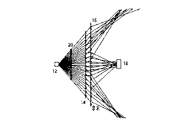
A detail description will now be given, with reference to Fig. 3 which
illustrates the first embodiment of an optical encoder according to the present invention.
CA 02214193 1997-10-20
The optical encoder shown in Fig. 3 comprises a light source 12, a first and
second array of lenslets 14 and 16 on which the light beam 20 is incident and a
displ~c~m~nt information obtaining means 18.
An LED or a semiconductor laser is used as the light source 12. The first array of
lenslets 14 is parallel to the second array of lenslets 16 and the first array of lenslets is
fixed and the second array of lenslets is movable in the direction indicated by an arrow R.
The displ~cçm~nt information obtaining means 18 can be a light receiving element or
photodetector array.
In the first embodiment as shown in Fig. 4, to generate dark and bright fringes,
lo the light beam 20 is incident on the first array of lenslets 14, the individual lenslets 22
defines the light beam. The second movable array of lenslets 16 to which the light beam
exiting from the first array of lenslets 14 is directed further defines the light beam into
dark and bright fringes as the light beam pass through the individual lenslets 24. By
displaying the second array of lenslets 16 in the direction indicated by an arrow R, the
light beam exiting from the first array of lenslets 14 is incident on the second movable
array of lenslets 16 at a different angle which will result in a shift in the position of the
dark and bright fringes. More specifically, if the movable second array of lenslets 16
moves a small distance corresponding to a single width W of a lenslet, the level of output
from the light receiving element 18 varies like a single period of sine wave as shown in
20 Fig. 5. By sensing this change, the amount of displacement of the movable array of
lenslets 16 can be determined.
Additionally, by replacing the light receiving element 18 with a group of light
detector 18a to 18d as illustrated in Fig. 6 which are placed in a one-dimensional array as
CA 02214193 1997-10-20
close to one another as the semiconductor technology will allow. Using such an
arrangement of four light detectors, four output signals are produced having the same
wave form but are offset from one another by 90 electrical signal which generate a
quadrature signal and may readily be converted to a digital signal indicative of the
position and direction of the movable array of lenslets 16 by a manner well known in the
art.
Fig. 7 is an illustration of a principle of an operation of the present invention. Any
ray that passes through a lens, or through a combination of lenses, can be described by
two parameters: by its direction c~ 0, with respect to the axis Z, and by its heighty O above
lo the axis Z. As show in Fig. 7 each array of lenslets is represented by the letter A: Al
represents the first array of lenslets, A2 represents the second array of lenslets... and AN
represents the N'h array of lenslets. Also, each lenslet in an array is treated as an optical
lens and can be represented by the letter L: L,l represent the first lenslets in first array A"
L,2 represent the second lenslet in the first array Al... and LNM represents the M'h lenslet
in the N'h array. Moreover, each lenslet L can be further represented by four other matrix:
Mlll is the matrix that transforms a non-paraxial ray into a paraxial ray for the optical
lens Lll, M"2 represents a matrix of the first refraction surface of the optical lens L" at
point B in Fig. 7, Mll3 represents the translation matrix of the lens Lll between point C
and D, Mll4 represents a matrix of the second refraction surface of the optical lens Lll at
20 point D. By combining matrices that represent individual lenslet, the position of an image
of the ray starting from point B to I can be obtained by the following expressions.
Lll= Mll4MII3MII2M111, L21=M214M213M212M211~- . ~LNI= MNl4MNl3MNl2MNll
CA 02214193 1997-10-20
~~o~ ~ao~
= LNI...L21LII
Io yo
If the array of lenslets AN is displaced in the direction indicated by the
arrow R, the Matrix MNIl ~--MNMI are the only matrices that are being changed, since the
position of the lenslet LN,...LNM are displaced. Thus MN"'...MNM,'represent the new
matrices. Therefore, the equation to find the image of the ray can be obtained by the
following expressions.
Lll= Mll4MII3MII2MIII, L21=M214M213M212M211~- . ~LNI'= MNl4MNl3MNl2MNll '
~~o'~ ~ao~
= LN11...L21LII
Io yo
The matrix method lends itself to various computer techniques for tracing a ray
0 through an optical system of a,l,i~laly complexity. The above expressions make it
possible to trace a ray and the image of a ray after an array of lenslets is being displaced.
Thus, by combining the above equations with modern optics theory and computer
progr~mming, it is possible to design different type of arrays of lenslets such that when
combine they will define light beam into dark and bright fringes.
As an example, Fig. 8 and Fig. 9 illustrate the variations of an optical encoder
using different combination of arrays of lenslets to define light beam into dark and bright
fringes by applying the principle described above. The optical encoder in Fig. 8
comprises a light source 12, a movable array of cylindrical lenslets 28 and a light
receiving element 18. Fig. 9 illustrates an optical encoder comprising a light source 12,
CA 02214193 1997-10-20
a first and second array of cylindrical lenslets 28 and 29, a movable array of biconcave
lenslets 30 and a light receiver element 18.
Anyone skills in the art can create a program using the principle describe above
that will simulate all the condition required to built a similar optical encoder to the
present invention. Although, the first embodiment of the present invention only requires
two arrays of lenslets, it can be easily deduced from the above principle and examples
that any number of arrays of lenslets can be used, as long as at least one of the array of
lenslets is a movable array. Moreover, lenslets of different sizes and shapes can be used
as long as the combined optical system defines the light beam into dark and bright
0 fringes..
Hereinafter, the array of lenslets referred to in the present invention is a lenticular
array which comprises of a plurality of individual lenslets 22 having a convex surface 25
opposite a flat surface 26 as shown in Fig. 4. However, it should be understood that each
lenslet 22 can be a cylindrical or spherical lens or can be of more complex optical system
and im~ging element, such as a hologram or other diffractive lens.
Diffractive lens can be formed of a grating comprising plurality of line, either
parallel or concentric which causes diffraction of incoming light to give the desire
focusing effect. One such type of diffractive lens id describe in the patent application of
H.P. Kleinknecht, from United State with Ser. No. 754,134 entitled "Optical Imager With
20 Diffractive Lenticular Array".
Another type of lenticular array can be in the fomm of a hologram. A hologram is
generated by the interference pattem between coherent beam passing through a mask and
CA 02214193 1997-10-20
a reference beam. Thus, a hologram having plurality of patterns which can defines light
beam into dark and bright fringes can be used as the lenticular array.
Although, the above-mentioned embodiments are linear optical encoder due to the
linear displacement of the movable array of lenslets 16, 28 or 30, a rotary optical encoder
can also be formed using the principle of the present invention.
Figs. 10 and 11 illustrate examples of a rotary encoder using the above-mentioned
principle. The rotary encoder of Fig. 10 comprises the light source 32, a fixed array of
lenslets 34, a rotatable array of lenslets 33 which is formed on a cylindrical surface and a
light receiving element 31. The optical encoder of Fig. 11 comprises the light source 36, a
0 fixed array of lenslets 37, a rotatable array of lenslets 35 which is formed on a plane
circular surface and a light receiving element 38. The rotatable arrays of lenslets 33 and
35 both rotate about an axis X.
One of the greatest advantage of the present invention using the principle
described above is in the application of two dimensional optical encoder. Conventional
two-dimensional optical encoders are made of a combination of two linear one-
tlim~n~ional optical encoder position at 90 degree from each other on the same plane
surface. Such a design can lead to a more complex and bulky apparatus and Illtim~tely
can increase the cost of production or in some case impossible to mini~hlrize the
apparal~ls. Thus a simple two-dimensional optical encoder as illustrates in Fig. 12 will
20 overcome the above-mentioned limitations.
A detail description will now be given, with reference to Fig.12 which illustrates
the second embodiment of the present invention. The two-dimensional encoder comprises
a light source 50, a first and second movable arrays of lenslets 51 and 52 which are
CA 02214193 1997-10-20
placed on the top of each other forming a single layer two-dimensional lenslet array, a
first and second fixed arrays of lenslets 48 and 49 and a light receiving elements 47 and
46. In the two-dimensional lenslets array, the longitl--lin~l axis of the lenslets 56 of the
array
of lenslets 51 extend along the X axis and the longit-l-1in~1 axis of the lenslets 58 of the
array of lenslets 52 extend along the Y axis. The fixed array of lenslets 48 and 49 are
positioned substantially perpendicular to each other and parallel above the two-
clim-~n~ional lenslet array. The beam of light is first incident on the two-dimensional
lenslets array, which is defined by the individual lenslet 56 and 58, the exited light beam
lo is then directed at the fixed array of lenslets 48 and 49. Each array of lenslet 48 and 49
will further defines the exiting light beam into two set dark and bright fringes. As the
two-tlimen~cional lenslet array is displaced parallel to the X axis, only the position of the
dark and bright fringes that are generated by the fixed array of lenslets 48 will change, for
only the angle of the incident light beam exiting from the two-dimensional lenslet array
will change relative to surface 60 of the individual lenslets 61. Similarly, if the two
dimensional lenslet array is displaced parallel to the Y axis, only the position of the dark
and bright fringes that are generated by the fixed array of lenslets 49 will change
position, for only the angle of the incident light beam exiting from the two dimensional
lenslet array will change relative to the surface 62 of the individual lenslet 63. That is, by
20 sensing the change in the position of the two set of dark and bright fringes, the light
receiving element 47 and 48 will generate a corresponding electrical signal which can be
used to determine the displacement of the two-dimensional lenslet array in the XY plane.
~ - -
CA 02214193 1997-10-20
Fig. 13 illustrates a two dimensional rotational optical encoder, which uses thesame principle described for the second embodiment in Fig. 12. The two-dimensional
rotational encoder comprises a light source 45, a first and second movable array of lenslet
43 and 44 which are formed on a cylindrical surface and inserted together forming a two
layer cylindrical array of lenslets, and light receiving elements 39 and 40. Thelongitudinal axis of the lenslets 68 of the array of lenslets 44 extend circularly along the
X axis and the longit~1tlin~1 axis of the lenslet 69 of the array of lenslets 43 extend
circularly along the Y axis. In order to generate a two-dimensional rotational encoder, the
movable array of lenslets 44 and 43 rotate around the X axis and is displaced along the
o direction provided by the arrow R.
Additionally, it is possible to create variations of the two-dimensional encoderillustrate in Fig. 12 and 13 by simply omitting the fixed arrays of lenslets 48 and 49 from
the embodiment in Fig. 12 and the fixed arrays of lenslets 44 and 43 from the
embodiment in Fig. 13.
It should be noted that having fully described a preferred embodiment of the
invention and various alternatives, those skilled in the art will recognize, given the
tea~hing herein, that numerous alternatives and equivalent exist which do not depart from
the scope of the invention. It is therefore intended that the invention not be limited by the
foregoing description, but only by the claims.
Additionally, in the above-mention embotlim~nt.c thereof having more than two
arrays of lenslets, any one of the array of lenslets may be a movable array of lenslets
while the other arrays are made to be fixed