Sélection de la langue

Search

Sommaire du brevet 2214303 

Énoncé de désistement de responsabilité concernant l'information provenant de tiers

Une partie des informations de ce site Web a été fournie par des sources externes. Le gouvernement du Canada n'assume aucune responsabilité concernant la précision, l'actualité ou la fiabilité des informations fournies par les sources externes. Les utilisateurs qui désirent employer cette information devraient consulter directement la source des informations. Le contenu fourni par les sources externes n'est pas assujetti aux exigences sur les langues officielles, la protection des renseignements personnels et l'accessibilité.

Disponibilité de l'Abrégé et des Revendications

L'apparition de différences dans le texte et l'image des Revendications et de l'Abrégé dépend du moment auquel le document est publié. Les textes des Revendications et de l'Abrégé sont affichés :

  • lorsque la demande peut être examinée par le public;
  • lorsque le brevet est émis (délivrance).
(12) Brevet: (11) CA 2214303
(54) Titre français: GARNITURE DE POIGNEE DE ROBINET DE C.W. A JOINT D'ETANCHEITE
(54) Titre anglais: FLUSH VALVE SEAL HANDLE PACKING
Statut: Durée expirée - au-delà du délai suivant l'octroi
Données bibliographiques
(51) Classification internationale des brevets (CIB):
  • E03D 1/34 (2006.01)
  • E03D 3/02 (2006.01)
  • E03D 3/06 (2006.01)
  • F16K 31/385 (2006.01)
(72) Inventeurs :
  • GRONWICK, JERRY P. (Etats-Unis d'Amérique)
(73) Titulaires :
  • SLOAN VALVE COMPANY
(71) Demandeurs :
  • SLOAN VALVE COMPANY (Etats-Unis d'Amérique)
(74) Agent: DENNISON ASSOCIATES
(74) Co-agent:
(45) Délivré: 2005-10-25
(22) Date de dépôt: 1997-08-29
(41) Mise à la disponibilité du public: 1998-03-06
Requête d'examen: 2000-07-17
Licence disponible: S.O.
Cédé au domaine public: S.O.
(25) Langue des documents déposés: Anglais

Traité de coopération en matière de brevets (PCT): Non

(30) Données de priorité de la demande:
Numéro de la demande Pays / territoire Date
08/707998 (Etats-Unis d'Amérique) 1996-09-06

Abrégés

Abrégé français

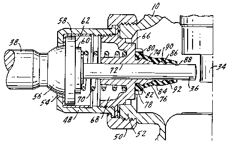
Un dispositif de chasse d'eau possède un corps comprenant une entrée et une sortie. Un siège de clapet situé dans le corps, dans le circuit d'écoulement entre l'entrée et la sortie, et un clapet situé dans le corps pouvant être rapproché ou éloigné du siège de clapet permettent de réguler le débit d'eau à travers le dispositif de chasse d'eau. Un ensemble poignée permettant de rapprocher et d'éloigner le clapet du siège de clapet comprend une douille fixée au corps et une poignée montée dans la douille pour permettre un mouvement de pivotement. Un piston est positionné en partie dans la douille et est en contact avec la poignée. Le mouvement de pivotement de la poignée provoque le mouvement axial du piston avec une partie du piston en position de contact avec le clapet pour provoquer le mouvement de celui-ci. Un ressort permet de solliciter le piston en direction de la poignée. Une bague est fixée à la douille et présente un orifice central dans lequel se déplace le piston. Un élément d'étanchéité est fixé à la bague et forme un joint avec celle-ci. L'élément d'étanchéité présente un passage central, avec le piston positionné dans ce passage central. L'élément d'étanchéité possède une pluralité de lobes d'étanchéité circonférentiels espacés les uns des autres, s'étendant vers l'intérieur, qui sont en contact étanche avec le piston à des endroits axialement espacés de celui-ci. Les lobes délimitent au moins un évidement entre eux et du lubrifiant est présent dans le au moins un évidement.


Abrégé anglais

A toilet flushing device has a body with an inlet and an outlet. There is a valve seat in the body in the flow path between the inlet and the outlet and a valve in the body movable toward and away from the valve seat to control water flow through the toilet flushing device. A handle assembly for causing movement of the valve toward and away from the valve seat includes a socket attached to the body and a handle mounted in the socket for pivotal movement. A plunger is positioned in part within the socket and is in contact with the handle. Pivotal movement of the handle causes axial movement of the plunger with a portion of the plunger being positioned for contact with valve for causing movement thereof. There is a spring for biasing the plunger toward the handle. A bushing is attached to the socket and has a central bore within which the plunger moves. A seal member is attached to the bushing and forms a seal therewith. The seal member has a central passage with the plunger being positioned within this central passage. The seal member has a plurality of spaced inwardly extending circumferential seal lobes which are in sealing contact with the plunger at axially spaced locations thereon. The lobes define at least one recess therebetween and there is lubricant within the at least one recess.

Revendications

Note : Les revendications sont présentées dans la langue officielle dans laquelle elles ont été soumises.


The embodiments of the invention in which an exclusive
property or privilege is claimed are defined as follows:
1. A toilet flushing device including a body, an
inlet and outlet in said body, a valve seat in said body in
the flow path between said inlet and outlet, valve means in
said body movable toward and away from said valve seat to
control water flow from said inlet to said outlet
a handle assembly for causing movement of said valve
means from a closed position on said valve seat to an open
position away from said valve seat, said handle assembly
including a socket attached to said body, a handle mounted
in said socket for pivotal movement, a plunger positioned
in part within said socket and in contact with said handle,
pivotal movement of said handle causing axial movement of
said plunger, a portion of said plunger being positioned
for contact with said valve means for causing movement
thereof, spring means biasing said plunger toward said
handle, a bushing attached to said socket and having a
central bore within which said plunger moves,
a seal member extending axially along said plunger and
attached to said bushing and forming a seal therewith, said
seal member having a central passage, said plunger being
positioned within said seal member central passage in a
static position and during axial movement of said plunger,
said seal member passage having three circumferentially
inwardly extending seal lobes which are in sealing contact
with said plunger at axially spaced locations thereon, each
lobe having edges lying in a single plane normal to the
plunger, one of said seal lobes being at an end of said
7

seal member, said lobes defining two spaced recesses
therebetween, with lubricant in said recesses, said seal
member having a radially inwardly extending projection at
one end thereof, an interlocking recess on said bushing,
with said seal member inward projection extending into said
recess to attach said seal member to said bushing, said
bushing having an axially extending tapered projection,
with an interior portion of said seal member conforming to
and being in contact with said axially extending tapered
projection, one of said inwardly extending circumferential
seal lobes being directly adjacent to and in contact with
the end of said tapered portion of said bushing.
8

Description

Note : Les descriptions sont présentées dans la langue officielle dans laquelle elles ont été soumises.


CA 02214303 2004-02-12
FLUSH VALVE SEAL HANDLE PACKING
~iE FIELD OF THE INVENTION
The present invention relates to flush valves or
flushometers as they are commonly designated which are used to
provide a measured amount of Water to flush a urinal or water
closet. The assignee of the present application, Sloan Valve
Company of Franklin Park, Illinois, sells several types of
flushometers arranged for manual operation, one of which is
marketed under the trademark ROYAL. The present invention is
specifically directed to the handle assembly for manually
operating the flushometer and more particularly to an improved
seal to prevent leakage of water from the body of the flushometer
out through the handle assembly.
The handle assembly includes a socket which mounts
to the body of the flushometer and a handle which pivotally moves
in the socket. Movement of the handle will cause a spring biased
plunger to move into the body of the flushometer and, in the
ROYAL brand flushometer, to trip a relief valve permitting a
venting of the pressure chamber to open the valve so that flush-
ing water may pass from the inlet to the outlet. A seal is
positioned on the plunger and is mounted to the bushing which
holds the plunger. The seal has a plurality of axially spaced
inwardly extending circumferential seal lobes which are in
contact With the plunger at axially spaced locations. The lobes
define recesses therebetween and there is lubricant within the
1

CA 02214303 1997-08-29
seal recesses.
SUMMARY OF THE INVENTION
The present invention relates to toilet room devices
and particularly to flushometers and more specifically to an
improved handle seal for a flushometer.
A primary purpose of the invention is to provide a
handle assembly which has an improved seal, preventing leakage
from the body of the flushometer out through the handle assembly.
Another purpose is a handle assembly which is simple
in construction and reliably operable.
Another purpose is a handle assembly for the use
described in which there are a plurality of spaced sealing point
with recesses for lubricant therebetween.
Other purposes will appear in_the ensuing specifica-
tion, drawings and claims.
BRIEF DESCRIPTION OF THE DRAWINGS
Fig. 1 is a cross section illustrating a flushometer
of the type described with the handle assembly shown thereon;
Fig. 2 is an enlarged cross section illustrating the
handle assembly; and
Fig. 3 is an enlarged cross section of the seal.
DESCRIPTION OF THE PREFERRED EMBODIMENT
The handle assembly of the present invention will be
described in connection with a flushometer of the type sold by
Sloan Valve Company under the trademark ROYAL. The invention
should not be limited to this particular type of flushometer
2

CA 02214303 1997-08-29
and is applicable in any flushometer in which movement of a
handle causes axial movement of a plunger to trip a relief valve.
The flushometer includes a body 10 having an inlet
connection 12 and an outlet connection 14. A diaphragm assembly
indicated generally at 16 includes a diaphragm 18 peripherally
held to the body 10 by an inner cover 20. The diaphragm is
seated upon a shoulder 22 at the upper end of body 10 and is
clamped in this position by the inner cover 20. An outer cover
24 is screwthreaded onto the body to hold the inner cover in
position.
The diaphragm assembly 16 is closed upon a valve seat
26 formed at the upper end of a barrel 28. The barrel 28 forms
the conduit connecting the valve seat with outlet 14. The
diaphragm assembly 16 includes a relief valve 30 having a down-
wardly extending stem 32 carrying a movable sleeve 34. Sleeve
34 is positioned for contact by a plunger 36 when operated by
a handle 38.
The diaphragm assembly 16 in addition to the diaphragm
18 and the relief valve 30, includes a retaining disk 40, a
refill ring 44, and a flow control ring 46. Further details of
the diaphragm assembly are disclosed in U.S. Patent 5,505,427
also owned by Sloan Valve Company.
The handle assembly of the present invention includes
a socket 48 which is held by a handle coupling 50 to an exter-
iorally threaded boss 52 forming a part of the flush valve body
10. The socket 48 has an opening 54 through which the handle
3

CA 02214303 1997-08-29
38 extends. The handle 38 has a spherical portion 56 which is
positioned within the opening 54 and provides for pivotal move-
ment of the handle relative to the socket. Directly adjacent
the spherical portion 56 there is an outwardly directed flange
58 of the handle which is seated within socket 48.
The plunger 36 has a flat end 60 which is in planer
contact with the flat end 62 of handle 38. When the handle 38
is pivotally moved within opening 54, it will cause axial inward
movement of the plunger 36 to contact the relief valve sleeve
34 to trip the relief valve for operation of the flush valve.
A bushing 66 is threaded to the interior of socket 48
and has a circumferential cavity 68 within which is positioned
a coil spring 70 which normally biases plunger 36 to the
unoperated position shown in the drawing. Bushing 66 has a
passage 72 within which the plunger 36 moves in an axial
direction to operate the flush valve. Bushing 66 has an axial
extension, indicated at 74, with a tapered exterior 76. Mounted
on the axial extension 74 of the bushing is a seal element 78.
The seal element 78 has an inwardly directed circumferential
projection 80 which extends within a recess 82 in the bushing
projection 74, thus attaching the seal element to the bushing.
The seal element 78 has a plurality, in this case
three, inwardly and circumferentially extending seal lobes 84,
86 and 88 each of which is in sealing contact with the exterior
of the plunger 36. The lobes 84, 86 and 88, define between them
4

CA 02214303 1997-08-29
a pair of circumferential recesses 90 and 92, which recesses
will contain a suitable lubricant for greasing the plunger to
facilitate its movement between operated and unoperated posi-
tions. The distance between lobes 84 and 88 is longer than the
stroke of plunger 36 which insures that the plunger is always
in contact with seal lobe 84 to protect the shaft from foreign
material. Seal lobe 88 has a sharp edge so that it functions
as a scraper, preventing foreign matter from entering the
lubricant recesses.
In operation, pivotal movement of handle 38 causes its
end surface 62 to move the plunger against the bias of spring
70, in an inward axial direction to where it contacts and tilts
the relief valve 30. This vents the pressure in the chamber
above the relief valve, causing the diaphragm to unseat from
seat 26 permitting a clear flow path from the inlet 12 to the
outlet 14.
The seal element 78 is particularly advantageous in
that it provides a plurality of separate sealing points between
its interior and the movable plunger. The.lobes 84, 86 and 88
provide such spaced seal areas and the recesses 90, 92 there-
between provide reservoirs for lubricant to provide for smooth
movement of the plunger between its operated and unoperated
positions. The combination of the multiple sealing points with
lubricant therebetween provides a complete seal preventing any
leakage of water from the interior of the flushometer body out
through the handle assembly.
5

CA 02214303 1997-08-29
Whereas the preferred form of the invention has been
shown and described herein, it should be realized that there may
be many modifications, substitutions and alterations thereto.
6

Dessin représentatif
Une figure unique qui représente un dessin illustrant l'invention.
États administratifs

2024-08-01 : Dans le cadre de la transition vers les Brevets de nouvelle génération (BNG), la base de données sur les brevets canadiens (BDBC) contient désormais un Historique d'événement plus détaillé, qui reproduit le Journal des événements de notre nouvelle solution interne.

Veuillez noter que les événements débutant par « Inactive : » se réfèrent à des événements qui ne sont plus utilisés dans notre nouvelle solution interne.

Pour une meilleure compréhension de l'état de la demande ou brevet qui figure sur cette page, la rubrique Mise en garde , et les descriptions de Brevet , Historique d'événement , Taxes périodiques et Historique des paiements devraient être consultées.

Historique d'événement

Description Date
Inactive : Périmé (brevet - nouvelle loi) 2017-08-29
Inactive : CIB de MCD 2006-03-12
Accordé par délivrance 2005-10-25
Inactive : Page couverture publiée 2005-10-24
Préoctroi 2005-08-11
Inactive : Taxe finale reçue 2005-08-11
Un avis d'acceptation est envoyé 2005-04-27
Lettre envoyée 2005-04-27
Un avis d'acceptation est envoyé 2005-04-27
Inactive : Approuvée aux fins d'acceptation (AFA) 2005-03-18
Modification reçue - modification volontaire 2004-12-23
Inactive : Dem. de l'examinateur par.30(2) Règles 2004-06-28
Modification reçue - modification volontaire 2004-02-12
Inactive : Dem. de l'examinateur par.30(2) Règles 2003-08-13
Lettre envoyée 2000-08-08
Exigences pour une requête d'examen - jugée conforme 2000-07-17
Toutes les exigences pour l'examen - jugée conforme 2000-07-17
Requête d'examen reçue 2000-07-17
Demande publiée (accessible au public) 1998-03-06
Inactive : CIB en 1re position 1997-12-04
Symbole de classement modifié 1997-12-04
Inactive : CIB attribuée 1997-12-04
Inactive : Certificat de dépôt - Sans RE (Anglais) 1997-11-04
Exigences de dépôt - jugé conforme 1997-11-04
Lettre envoyée 1997-11-04
Demande reçue - nationale ordinaire 1997-11-03

Historique d'abandonnement

Il n'y a pas d'historique d'abandonnement

Taxes périodiques

Le dernier paiement a été reçu le 2005-07-12

Avis : Si le paiement en totalité n'a pas été reçu au plus tard à la date indiquée, une taxe supplémentaire peut être imposée, soit une des taxes suivantes :

  • taxe de rétablissement ;
  • taxe pour paiement en souffrance ; ou
  • taxe additionnelle pour le renversement d'une péremption réputée.

Veuillez vous référer à la page web des taxes sur les brevets de l'OPIC pour voir tous les montants actuels des taxes.

Titulaires au dossier

Les titulaires actuels et antérieures au dossier sont affichés en ordre alphabétique.

Titulaires actuels au dossier
SLOAN VALVE COMPANY
Titulaires antérieures au dossier
JERRY P. GRONWICK
Les propriétaires antérieurs qui ne figurent pas dans la liste des « Propriétaires au dossier » apparaîtront dans d'autres documents au dossier.
Documents

Pour visionner les fichiers sélectionnés, entrer le code reCAPTCHA :


Pour visualiser une image, cliquer sur un lien dans la colonne description du document. Pour télécharger l'image (les images), cliquer l'une ou plusieurs cases à cocher dans la première colonne et ensuite cliquer sur le bouton "Télécharger sélection en format PDF (archive Zip)" ou le bouton "Télécharger sélection (en un fichier PDF fusionné)".

Liste des documents de brevet publiés et non publiés sur la BDBC .

Si vous avez des difficultés à accéder au contenu, veuillez communiquer avec le Centre de services à la clientèle au 1-866-997-1936, ou envoyer un courriel au Centre de service à la clientèle de l'OPIC.


Description du
Document 
Date
(aaaa-mm-jj) 
Nombre de pages   Taille de l'image (Ko) 
Dessin représentatif 1998-03-18 1 14
Abrégé 1997-08-29 1 34
Description 1997-08-29 6 192
Revendications 1997-08-29 2 67
Dessins 1997-08-29 1 44
Page couverture 1998-03-18 2 84
Description 2004-02-12 6 192
Revendications 2004-02-12 2 56
Revendications 2004-12-23 2 92
Dessin représentatif 2005-03-21 1 18
Page couverture 2005-09-30 1 54
Courtoisie - Certificat d'enregistrement (document(s) connexe(s)) 1997-11-04 1 116
Certificat de dépôt (anglais) 1997-11-04 1 164
Rappel de taxe de maintien due 1999-05-03 1 111
Accusé de réception de la requête d'examen 2000-08-08 1 177
Avis du commissaire - Demande jugée acceptable 2005-04-27 1 161
Correspondance 2005-08-11 1 33