Sélection de la langue

Search

Sommaire du brevet 2214520 

Énoncé de désistement de responsabilité concernant l'information provenant de tiers

Une partie des informations de ce site Web a été fournie par des sources externes. Le gouvernement du Canada n'assume aucune responsabilité concernant la précision, l'actualité ou la fiabilité des informations fournies par les sources externes. Les utilisateurs qui désirent employer cette information devraient consulter directement la source des informations. Le contenu fourni par les sources externes n'est pas assujetti aux exigences sur les langues officielles, la protection des renseignements personnels et l'accessibilité.

Disponibilité de l'Abrégé et des Revendications

L'apparition de différences dans le texte et l'image des Revendications et de l'Abrégé dépend du moment auquel le document est publié. Les textes des Revendications et de l'Abrégé sont affichés :

  • lorsque la demande peut être examinée par le public;
  • lorsque le brevet est émis (délivrance).
(12) Brevet: (11) CA 2214520
(54) Titre français: ELIMINATION DE DEBRIS
(54) Titre anglais: DEBRIS REMOVAL
Statut: Périmé et au-delà du délai pour l’annulation
Données bibliographiques
(51) Classification internationale des brevets (CIB):
  • B23Q 11/00 (2006.01)
  • B08B 15/04 (2006.01)
(72) Inventeurs :
  • BAKER, ANTHONY THOMAS (Royaume-Uni)
(73) Titulaires :
  • BAE SYSTEMS PLC
(71) Demandeurs :
  • BAE SYSTEMS PLC (Royaume-Uni)
(74) Agent: SMART & BIGGAR LP
(74) Co-agent:
(45) Délivré: 2003-01-28
(86) Date de dépôt PCT: 1996-12-18
(87) Mise à la disponibilité du public: 1997-07-17
Requête d'examen: 1998-01-27
Licence disponible: S.O.
Cédé au domaine public: S.O.
(25) Langue des documents déposés: Anglais

Traité de coopération en matière de brevets (PCT): Oui
(86) Numéro de la demande PCT: PCT/GB1996/003139
(87) Numéro de publication internationale PCT: GB1996003139
(85) Entrée nationale: 1997-09-03

(30) Données de priorité de la demande:
Numéro de la demande Pays / territoire Date
9600117.7 (Royaume-Uni) 1996-01-04
9624061.9 (Royaume-Uni) 1996-11-20

Abrégés

Abrégé français

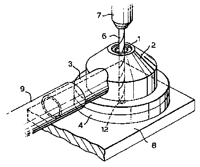
L'invention concerne un dispositif destiné à un système d'élimination de débris par aspiration, ce dispositif comprenant un récipient pour recueillir les débris ayant une première ouverture dans laquelle peut être inséré de manière amovible un outil de coupe, une seconde ouverture qui peut être reliée à une source de vide et une troisième ouverture dont la face circonférentielle ouverte est destinée a venir sensiblement en contact avec le matériau subissant une opération de coupe, pour que, en service, à mesure que les débris sont produits par l'action de l'outil de coupe sur ledit matériau, ils soient recueillis dans le récipient et extraits par la seconde ouverture, par l'effet de l'aspiration.


Abrégé anglais


An attachment
for use with a vacuum
powered debris removal
system, said attachment
comprising a debris
collection bowl, said bowl
having a first aperture
through which a material
cutting tool may be
removably inserted, a
second aperture through
which a vacuum source
may be connected, and
a third aperture the open
circumferential face of
which is designed to lie
substantially in contact
with a material undergoing
a cutting operation, such
that in use, as debris is
generated by the action
of the cutting tool on said
material, substantially all
debris is collected in said
bowl and thereby extracted
through the second
aperture by the action of
the vacuum source.

Revendications

Note : Les revendications sont présentées dans la langue officielle dans laquelle elles ont été soumises.


-5-
CLAIMS
1. An attachment for use with a vacuum powered debris removal system, said
attachment comprising a transparent debris collection bowl having a first
aperture
bounded by a bearing surface through which a material cutting tool may be
removably
inserted, a second aperture to which a vacuum source may be connected, and a
third
aperture having an open circumferential face designed to lie substantially in
contact
with a material undergoing a cutting operation, and said attachment further
comprising a replaceable transparent insert removably housed within said
debris
collection bowl, said insert having three apertures corresponding respectively
to said
first, second and third apertures in the debris collection bowl.
2. An attachment for use with a vacuum powered debris removal system as
claimed in
claim 1 wherein the bearing surface of said first aperture in the debris
collection bowl
is metallic.

Description

Note : Les descriptions sont présentées dans la langue officielle dans laquelle elles ont été soumises.


CA 02214520 2002-O1-21
-I-
DEBRIS REMOVAL
This invention relates to a vacuum cleaning attachment and more specifically
but not
exclusively to the use of such an attachment for the removal of swarf or
debris in drilling
and/or grinding operations.
The use of vacuum cleaning attachments is well known for domestic dust and
debris
removal, and additionally in manufacturing/industrial applications where large
volumes of
debris or swarf are required to be moved from the areas surrounding machining
operations.
The usual method by which industrial swarf or debris is removed relies on
specifically shaped
vacuum nozzle attachments being placed on or near to the head of a machining
or cutting
device such that as produced a proportion of the debris can be removed from
the area of the
work piece. Aside from this industrial machining use the vast majority of
vacuum cleaning
applications are applied after debris has been produced and allowed to settle
either at ground
level, on the machine bed or on the work piece itself.
Our invention allows the removal of substantially all of the debris or swarf
produced
by the cutting of a material, thereby significantly reducing the time and
effort required to
apply vacuum cleaning techniques after debris has settled either on or away
from a work
piece.
According to the present invention there is provided an attachment for use
with a
vacuum powered debris removal system, said attachment comprising a transparent
debris
collection bowl having a first aperture bounded by a bearing surface through
which a material
cutting tool may be removably inserted, a second aperture to which a vacuum
source may be
connected, and a third aperture having an open circumferential face designed
to lie
substantially in contact with a material undergoing a cutting operation, and

CA 02214520 2002-O1-21
-2-
said attachment further comprising a replaceable transparent insert removably
housed within
said debris collection bowl, said insert having three apertures corresponding
respectively to
said first, second and third apertures in the debris collection bowl.
A specific embodiment of the invention will now be described by way of an
example
with reference to the accompanying drawings in which;
Figures l, 2 and 3 show perspective, top elevation and cross section views
respectively of a vacuum attachment in accordance with the invention.
Figure 4 shows a perspective view of an insert
Figure 5 shows a diagrammatic representation of a vacuum attachment in
accordance
with the invention in situ on a work piece.
Referring to the drawings, Figures 1 to 3 show the transparent body of the
vacuum
attachment or shell 2 with a first aperture 1 bounded by a steel washer and/or
bush, a second
aperture 3 providing a releasable attachment position for a vacuum hose (9
shown in Figure
5) and a seal 4 bounding the circumference of a third aperture to enable
adequate suction to
be developed within the body of the vacuum attachment 2, hereby holding said
attachment to
a work piece 8 undergoing the cutting/drilling/machining operation.
f-~i~;ures 2 and 3 show plan and cross sectional view of the vacuum attachment
respectively.
Figure 4 shows an insert 5 designed to fit inside the body of the vacuum
attachment 2,
having a first aperture 10 which corresponds to the position of the first
aperture 1 in the main
body of the vacuum attachment 2, and a second aperture 14 which corresponds to
the position

CA 02214520 2002-O1-21
-3-
of the vacuum aperture 3 in the body of the vacuum attachment 2, thereby
allowing the
respective insertion of a drill bit or tool 6 and providing a passage for the
vacuum source (not
shown) to reach debris in the body of the vacuum attachment 2..
Figure S shows the vacuum attachment 2 in position on a work piece 8, having a
vacuum source connected by a releasably attachable pipe 9 to a channel or pipe
leading to the
aperture 3 in the main body of the vacuum attachment 2. When vacuum suction is
applied to
the pipe 9 the attachment 2 is held onto the work piece 8 by the force of said
vacuum, and the
seal 4 serves to substantially remove the possibility of leakage of air into
the inner bowl 2. A
plastic insert 5 is positioned within this inner bowl 2 is located such that
the apertures 1 and
are coincident, thereby providing a path for the drill bit 6 to contact the
work piece 8 at the
required position 12. As the drill bit 6, powered by the drill 7 begins to cut
into the work
piece 8, swarf and debris will be produced, which, due to the applied vacuum,
will be drawn
through the aperture 3 and into the vacuum source pipe 9. The insert S serves
to prevent
damage to the inner surface of the transparent vacuum attachment bowl 2,
thereby allowing
adequate visibility of the cutting operation at the point of contact 12 on the
work piece 8.
The dimensions of the vacuum attachment bowl, 2 the aperture 1 and the work
face
aperture surrounded by the sealing ring 4 may be varied to suit any size of
drill bit 6, or
indeed any other form of cutting bit which produces swarf or debris and could
be introduced
through an aperture 1 to its required point of contact 12 on a work piece 8.
The provision of
the sealing ring 4 enables sufficient suction to be developed within the
vacuum attachment 2
such that the said attachment will adhere to the work surface 8 during the
cutting process but
can be easily removed subsequently by its operator. There may be applications
in which full
contact of this sealing ring 4 may not be possible due to the location of the
required drilling

CA 02214520 2002-O1-21
-4-
position 12 being, for example, at an edge, in which case sufficient suction
would be made
available to remove substantially all debris and swarf thereby causing only a
small reduction
in the effectiveness of the apparatus.
Materials which could be utilised for the manufacture of such vacuum
attachments
include transparent plastics such as polycarbonates. The bearing surface
surrounding the
aperture 1 would ideally be metallic to enable adequate protection of the bowl
material 2, a
suitable material being hardened steel.

Dessin représentatif
Une figure unique qui représente un dessin illustrant l'invention.
États administratifs

2024-08-01 : Dans le cadre de la transition vers les Brevets de nouvelle génération (BNG), la base de données sur les brevets canadiens (BDBC) contient désormais un Historique d'événement plus détaillé, qui reproduit le Journal des événements de notre nouvelle solution interne.

Veuillez noter que les événements débutant par « Inactive : » se réfèrent à des événements qui ne sont plus utilisés dans notre nouvelle solution interne.

Pour une meilleure compréhension de l'état de la demande ou brevet qui figure sur cette page, la rubrique Mise en garde , et les descriptions de Brevet , Historique d'événement , Taxes périodiques et Historique des paiements devraient être consultées.

Historique d'événement

Description Date
Inactive : CIB de MCD 2006-03-12
Le délai pour l'annulation est expiré 2004-12-20
Lettre envoyée 2003-12-18
Accordé par délivrance 2003-01-28
Inactive : Page couverture publiée 2003-01-27
Inactive : Taxe finale reçue 2002-10-15
Préoctroi 2002-10-15
Un avis d'acceptation est envoyé 2002-04-16
Lettre envoyée 2002-04-16
Un avis d'acceptation est envoyé 2002-04-16
Inactive : Approuvée aux fins d'acceptation (AFA) 2002-04-05
Modification reçue - modification volontaire 2002-01-21
Inactive : Lettre officielle 2001-12-12
Inactive : Dem. de l'examinateur par.30(2) Règles 2001-11-28
Lettre envoyée 2000-11-15
Inactive : Acc. réc. RE - Pas de dem. doc. d'antériorité 1998-05-22
Inactive : Dem. traitée sur TS dès date d'ent. journal 1998-05-22
Inactive : Renseign. sur l'état - Complets dès date d'ent. journ. 1998-05-22
Lettre envoyée 1998-02-20
Modification reçue - modification volontaire 1998-02-13
Exigences pour une requête d'examen - jugée conforme 1998-01-27
Toutes les exigences pour l'examen - jugée conforme 1998-01-27
Requête d'examen reçue 1998-01-27
Inactive : Correspondance - Transfert 1997-11-21
Inactive : CIB attribuée 1997-11-20
Symbole de classement modifié 1997-11-20
Inactive : CIB en 1re position 1997-11-20
Inactive : Lettre de courtoisie - Preuve 1997-11-12
Inactive : Notice - Entrée phase nat. - Pas de RE 1997-11-07
Demande reçue - PCT 1997-11-05
Inactive : Transfert individuel 1997-10-07
Demande publiée (accessible au public) 1997-07-17

Historique d'abandonnement

Il n'y a pas d'historique d'abandonnement

Taxes périodiques

Le dernier paiement a été reçu le 2002-11-18

Avis : Si le paiement en totalité n'a pas été reçu au plus tard à la date indiquée, une taxe supplémentaire peut être imposée, soit une des taxes suivantes :

  • taxe de rétablissement ;
  • taxe pour paiement en souffrance ; ou
  • taxe additionnelle pour le renversement d'une péremption réputée.

Les taxes sur les brevets sont ajustées au 1er janvier de chaque année. Les montants ci-dessus sont les montants actuels s'ils sont reçus au plus tard le 31 décembre de l'année en cours.
Veuillez vous référer à la page web des taxes sur les brevets de l'OPIC pour voir tous les montants actuels des taxes.

Historique des taxes

Type de taxes Anniversaire Échéance Date payée
Taxe nationale de base - générale 1997-09-03
Requête d'examen - générale 1998-01-27
TM (demande, 2e anniv.) - générale 02 1998-12-18 1998-11-18
TM (demande, 3e anniv.) - générale 03 1999-12-20 1999-11-22
Enregistrement d'un document 2000-10-12
TM (demande, 4e anniv.) - générale 04 2000-12-18 2000-11-24
TM (demande, 5e anniv.) - générale 05 2001-12-18 2001-11-23
Taxe finale - générale 2002-10-15
TM (demande, 6e anniv.) - générale 06 2002-12-18 2002-11-18
Titulaires au dossier

Les titulaires actuels et antérieures au dossier sont affichés en ordre alphabétique.

Titulaires actuels au dossier
BAE SYSTEMS PLC
Titulaires antérieures au dossier
ANTHONY THOMAS BAKER
Les propriétaires antérieurs qui ne figurent pas dans la liste des « Propriétaires au dossier » apparaîtront dans d'autres documents au dossier.
Documents

Pour visionner les fichiers sélectionnés, entrer le code reCAPTCHA :


Pour visualiser une image, cliquer sur un lien dans la colonne description du document. Pour télécharger l'image (les images), cliquer l'une ou plusieurs cases à cocher dans la première colonne et ensuite cliquer sur le bouton "Télécharger sélection en format PDF (archive Zip)" ou le bouton "Télécharger sélection (en un fichier PDF fusionné)".

Liste des documents de brevet publiés et non publiés sur la BDBC .

Si vous avez des difficultés à accéder au contenu, veuillez communiquer avec le Centre de services à la clientèle au 1-866-997-1936, ou envoyer un courriel au Centre de service à la clientèle de l'OPIC.


Description du
Document 
Date
(aaaa-mm-jj) 
Nombre de pages   Taille de l'image (Ko) 
Dessin représentatif 2002-12-30 1 13
Description 1997-09-02 3 144
Abrégé 1997-09-02 1 54
Revendications 1997-09-02 1 18
Dessins 1997-09-02 2 39
Abrégé 1998-08-20 1 54
Dessin représentatif 1997-12-01 1 7
Description 2002-01-20 4 140
Revendications 2002-01-20 1 23
Avis d'entree dans la phase nationale 1997-11-06 1 193
Courtoisie - Certificat d'enregistrement (document(s) connexe(s)) 1998-02-19 1 118
Accusé de réception de la requête d'examen 1998-05-21 1 173
Rappel de taxe de maintien due 1998-08-18 1 115
Avis du commissaire - Demande jugée acceptable 2002-04-15 1 166
Avis concernant la taxe de maintien 2004-02-11 1 175
Correspondance 1997-11-11 1 30
PCT 1997-09-02 4 137
Correspondance 2001-12-11 1 19
Correspondance 2002-10-14 1 36
Taxes 1998-11-17 1 42
Taxes 1999-11-21 1 38
PCT 1998-02-08 4 111