Note : Les descriptions sont présentées dans la langue officielle dans laquelle elles ont été soumises.
CA 02215019 2005-07-08
MATTRESS INNERSPRING STRUCTURE HAVING COAXIAL COIL
UNITS
Field of the Invention
This invention relates generally to mattress innerspring
structures and specifically to an innerspring structure having sections of
enhanced firmness.
Background of the Invention
Conventionally, mattress innerspring structures
comprise a plurality of coil springs or coils which are positioned
-1-
CA 02215019 1997-09-10
WO 96129524 PC"T/US96/03922
adjacent one another to extend between top and bottom face
surfaces of a mattress. The coils are usually arranged in rows
which determine the length and width of the innerspring structure.
When individual coil springs or coils are used, they are held ,
together by various means to form a unitary innerspring structure.
Alternatively, a row of coils may be formed from a single
continuous piece of wire wherein each of the single coils are
connected in the row by interconnecting segments. The rows are
then fixed together to form the innerspring structure. Examples of
such spring assemblies having rows formed of a continuous piece
of wire are disclosed in U.S Patent Nos. 4,358,097 and 4,488,712
which are commonly owned with the present application.
The coils in the innerspring structure are typically
formed very similar to each other, having generally the same coil
diameter and similar stiffness, as dictated by the gauge of wire
used to make the coils and the number of turns or pitch of each
coil. Therefore, the top surface of a typical mattress will have
generally equal firmness throughout the length and width of the
mattress made from such an innerspring structure.
However, it is often desirable to make certain areas on
the mattress more firm than other areas of the mattress. For
-2-
CA 02215019 1997-09-10
1~'O 96/29524 PCTIUS96J03922
example, it may be desirable to firm up the center section of the
mattress which receives a majority of the weight from a person
' lying thereon. Further, it may be desirable to make the edge of a
mattress more firm or durable to withstand pressures created when
a person sits on the end of their bed.
Varying the stiffness of individual coils, such as by
using different wire gauges and/or different numbers of coil turns, it
might be possible to change the firmness in certain areas of an
innerspring. However, as may be appreciated, such an undertaking
would require constant conversion of the coil forming machine, and
thus would result in a substantial cost increase attributable to both
labor for the machine conversion and the delay in forming the
innerspring structures. Furthermore, the availability of various
different wire materials and gauges for forming different coils for a
single innerspring structure would have to be coordinated.
Therefore, such an approach is impractical from a cost standpoint.
It is also desirable to vary the firmness in certain areas
of an innerspring structure which utilizes continuous coil spring
units. Such continuous coil spring products have met with
considerable commercial success, primarily because considerably
less material is required for the same degree of firmness in such a
-3-
CA 02215019 1997-09-10
R'O 96/29524 PCT/US96/03922
spring product than has been employed in spring assemblies which
utilize rows of interconnected individual coil springs. However, the
spring products made from these continuous coil springs have been
found to be difficult or very expensive to modify in order to obtain ,
sections of the product which are more firm than other sections of
the same spring product. Varying the wire gauge or coil turns of a
particular coil or coils in the product is not a practical option,
because all coils are formed of a continuous piece of wire.
Furthermore, breaking a particular continuous row of coils into
discontinuous sections would destroy many of the benefits of the
continuous coil spring product. Therefore, it is an objective of the
present invention to increase the firmness in selected areas of a
mattress.
It is a further objective to increase the durability of
selected areas on a mattress which receive a high amount of
loading during normal usage.
Accordingly, it is another objective of the invention to
provide an innerspring structure which is more firm and provides
greater support in certain areas thereon than in other areas.
-4-
CA 02215019 1997-09-10
WO 96/29524 PCTIL1S96103922
Furthermore, it is an objective of the invention to
provide such an innerspring structure at a relatively low cost and
' with a relatively uncomplicated design.
It is another objective of the invention to create a
continuous coil spring product which is so constructed that various
sections of the product have varied degrees of firmness.
It is still another objective to provide a continuous coil
spring product and a method for constructing same which will not
require substantial variations in the assembly process in order to
form sections of the product with varying firmness.
Summary of the Invention
In accordance with the above-stated objectives, an
innerspring structure utilizes reinforced coil units having a coil
within a coil design constructed to form coaxial coil units. The
coaxial coil units are coupled together into a unitary innerspring
structure by helical lacing wire.
In one embodiment, the innerspring structure
comprises a plurality of individual, side-by-side coils, referred to
herein as outer coils, which extend generally parallel to one another
and are arranged in aligned rows. The outer coils have opposing
end turns which collectively form top and bottom face surfaces of
-5-
CA 02215019 1997-09-10
WO 96/29524 PCT/US96/03922
the innerspring structure. Selected rows or selected areas of the
innerspring structure further comprise one or more individual inner
coils which extend between the top and bottom face surfaces of
the structure. The inner coils are each wound and positioned
generally coaxially within a respective outer coil, such that the end
turns of the inner and outer coils are adjacent each other. The
inner and outer coils form generally coaxial coil units. A matrix of
helical lacing wires connects the inner and outer coils together at
the end turns to form a reinforced generally coaxial coil unit, having
a coil within a coil. The reinforced coil units have enhanced
firmness or stiffness relative to just the unitary outer coils or just
the inner coils. Preferably, the inner and outer coils are just pushed
or positioned together from the sides thereof to form the coaxial
units. Accordingly, the terms "inner" and "outer" are used
primarily for reference and do not necessarily indicate the overall
orientations of the coils within the coaxial spring unit.
The lacing matrix also connects the aligned rows of
coils together. The lacing matrix includes a plurality of spaced
apart helical wires which extend generally parallel one another and
generally perpendicular to the aligned rows. Each wire wraps
together the end turns of adjacent coils such that each coil within a .
-6-
CA 02215019 1997-09-10
WO 96129524 PCTlUS96103922
row is connected to an adjacent coil in that row. The rows of
reinforced coil units and rows of unitary outer coils are connected
together to form a unitary innerspring structure. Another helical
wire is wound around the periphery of the innerspring structure to
connect peripheral coils to a thick border wire for enhanced edge
firmness in the innerspring structure. The rows or areas of the
innerspring structure, which include the coaxial units of inner coils
within outer coils, create an area on the structure having a
stiffness or firmness which is higher than those areas which only
utilize unitary outer coils.
In one embodiment of the invention, each coil unit
within a selected row or rows of coils utilizes an inner coil within
an outer coil, such that reinforced rows of coaxial coil units are
produced. Alternatively, only one or a selected number of units
within a particular row might be the reinforced coaxial unit having a
coil within a coil design. Similarly, all of the peripheral coils
coupled to the border wire might be reinforced coaxial coil units to
strengthen the sides of the innerspring structure. The respective
inner and outer coils of a reinforced coil unit preferably have the
same pitch and the same winding direction, i.e., left hand or right
hand winding. Furthermore, the coils are formed such that the end
_7_
CA 02215019 1997-09-10
WU 96!29524 PCT/US96/03922
turns and intermediate turns of each of the inner and outer coils
have the same diameter. As such, the inner and outer coils
preferably have a similar shape and nest together to form a coil unit
with a double wire thickness to provide the desired firmness in ,
selected areas of the mattress. The coils, including any inventive
coaxial coil units, are positioned together and laced together. Since
the inner and outer coils are generally co-extensive in each coaxial
unit, the coaxial unit has generally equal support strength or
firmness along its length.
An alternative embodiment of the invention utilizes a
continuous coil spring product positioned with a similar continuous
coil spring product such that the two products interact and form a
row of adjacent coaxial coil units which generally have an inner coil
with an outer coil. Each row generally consists of a plurality
adjacent coil pairs which are interconnected by a Z-shaped wire
segments positioned proximate the top and bottom planes of the
coil rows and staggered such that each coil is connected to an
adjacent coil either proximate the top plane or the bottom plane.
When individual rows of continuous coil springs are positioned
adjacent each other to form an innerspring structure, the various Z-
_g_
CA 02215019 1997-09-10
WO 96/29524 PCTlL1S961D3922
shaped interconnecting segments are aligned both in rows and in
columns in the top and bottom planes of the innerspring structure.
To form the coaxial coil units of the present invention,
a row of outer coils, formed from a continuous piece of wire, is
positioned as a row of the innerspring structure. A row of inner
coils, also formed from a continuous piece of wire, is then
positioned generally parallel to the row of outer coils such that the
various inner and outer coils intermesh and the respective Z-shaped
interconnecting segments are aligned and generally overlapped to
form the reinforced coaxial coil units of the invention. As
referenced above, the designations of "inner" and "outer" are
utilized for reference and do not imply that one set of coils has
turns with larger diameters than another set of coils or that the
inner set of coils fits completely within the outer set of coils.
Preferably, the coil units in the row of outer coils have the same
number of turns (pitch) and turn diameters as the coil units in the
row of inner coils such that they would generally be
interchangeable. To form the coaxial coil units, a row of outer coils
is positioned generally parallel to a row of inner coils. The coil
rows are then moved together and intermeshed to form a row of
coaxial coil units in accordance with the principles of the invention,
_g_
CA 02215019 1997-09-10
WO 96/29524 PCT/US96/03922
similar to the way in which individual coils might be positioned
together; however, entire rows are intermeshed simultaneously.
In order to form an innerspring structure having
particular areas of varying firmness, the rows of coaxial coils are ,
positioned in the particular area of the innerspring structure.
Preferably, the rows extend transversely on the innerspring
structure. Additional single continuous rows of coils are then
positioned on either side of the rows of coaxial units, as
appropriate, to form the remainder of the innerspring structure.
The Z-shaped segments of the various adjacent rows of single coils
and coaxial coils which interconnected adjacent pairs of coils or
pairs of coaxial coil units within each row are positioned so that
they overlap. The overlapped portions or sections of the Z-shaped
segments are then tied together by helical wire connectors.
A first set of helical wire connectors will be disposed
within the top plane of the upper innerspring surface so as to join
together overlap portions of upper Z-shaped interconnection
segments. Similarly, a second set of helical wire connectors lie
within the bottom plane of the innerspring surface and join together
overlapped portions of lower Z-shaped interconnection segments.
The length of each helical wire is approximately the same as the
- 10-
CA 02215019 1997-09-10
WO 96/29524 PCTIUS96103922
length of the connected rows, which preferably defines the width
of the innerspring structure. In accordance with the principles of
the invention, the rows might also be longitudinal rows if it is
desirable to firm up various sections of the innerspring structure in
the longitudinal direction as opposed to the transverse direction.
The helical wire connectors connect together
overlapping Z-shaped interconnection segments of the inner and
outer coils to form the coaxial coil units. The helical wires also
connect together the various adjacent rows to form the innerspring
structure. Once the various rows of reinforced coaxial coil units
are constructed, and adjacent rows are secured together, the entire
innerspring structure may be secured around its perimeter to a
border wire utilizing another helical wire connector as part of the
lacing matrix for the innerspring structure.
Therefore, the innerspring structure of the present
invention provides the desired increased firmness and durability for
selected areas of the mattress utilizing reinforced coil units having
coils within coils laced by helical lacing wire. The inner and outer
coils utilized to form the reinforced coil unit are preferably similar
and therefore, the complexity of manufacturing the innerspring
structure is not drastically increased over the process used to make
- 11 -
CA 02215019 1997-09-10
WO 96/29524 PCT/US96/03922
a conventional innerspring structure which has the same firmness
throughout. Furthermore, no special wire or coiling techniques are
necessary for creating the reinforced coil units, thereby keeping
manufacturing costs to a minimum. The inner and outer coils are .
positioned together to form the coaxial units. The present
invention further presents an innerspring structure utilizing
continuous coil spring units in combination with rows of coaxial coil
units for varying the firmness characteristics of the innerspring
while maintaining the desirable characteristics of the continuous
coil spring product.
The above and other objects and advantages of the
present invention shall be made apparent from the accompanying
drawings and the description thereof.
Brief Descriation of the Drawing
Fig. 1 is a top view of the innerspring structure of the
present invention utilizing reinforced coil units laced together by a
helical wire matrix;
Fig. 2 is cross-sectional view taken on lines 2-2 of the
innerspring structure of Fig. 1;
- 12-
CA 02215019 1997-09-10
WU 96/29524 PCTlL1S961U3922
Fig. 3 is a cross-sectional view along lines 3-3 of Fig.
1 illustrating a reinforced coil unit of the invention helically laced to
a border wire;
Fig. 4A is a perspective view of a continuous coil
spring product having coaxial coil units in accordance with the
principles of the invention;
Fig. 4B is a perspective view of a continuous spring
product of inner coils positioned to intermesh with a continuous
spring product of outer coils to form coaxial coil units;
Fig. 5 is a plan view of an innerspring structure of the
invention with a row of coaxial coil units;
Fig. 6 is a diagrammatic plan view in which each coil
pair and coaxial coil unit pair in each row is designated by block
lines constituting continuations of the Z-shaped coil interconnection
segments;
Fig. 7 is an enlarged fragmentary top plan view of a
portion of the assembly shown in Fig. 6;
Fig. 8 is a top plan view, partially broken away of an
alternative embodiment of an innerspring structure of the invention;
Fig. 9 is a diagrammatic plan view of the embodiment
of Fig. 8 in which each coil pair and coaxial coil unit pair in each
- 13-
CA 02215019 1997-09-10
WO 96/29524 PCT/US96/03922
row is designated by block lines constituting continuations of the Z-
shaped coil interconnection segments.
The accompanying drawings, which are incorporated
in and constitute a part of this specification, illustrate embodiments
of the invention and, together with a general description of the
invention given above, and the detailed description of the
embodiments given below, serve to explain the principles of the
invention.
Detailed Description of Specific Embodiments
Fig. 1 illustrates the innerspring structure 10, which
utilizes the reinforced coil units of the present invention.
Innerspring structure 10 includes a plurality of coils 12, which are
referred to as outer coils for the purpose of this invention. Some of
the outer coils 12 are utilized in conjunction with other coils 14,
referred to as inner coils, which are placed within certain of the
outer coils 12 to form reinforced coil units 16 as described further
hereinbelow. Although, the inner coils 14 and respective outer
coils 12 are preferably coaxial, each coil and its turns may vary in
orientation with respect to the other. Therefore, the terms "inner"
and "outer" are used primarily for reference and do not necessarily
- 14-
CA 02215019 1997-09-10
WO 96/29524 PCTIUS96103922
indicate the overall coil orientations within the reinforced coil unit
16.
To form the body of innerspring structure 10, the
- outer coils 12 are arranged side-by-side with each other and are
placed in aligned rows 18. The outer coils 12 consist of a series of
wire turns and each coil has opposing end turns 20, 22 (see Fig.
2). The respective end turns 20, 22 of the coils 12 collectively lie
in generally the same opposing planes and define a top face surface
24 and an opposing bottom face surface 26, of the innerspring
structure 10. A reinforced border wire 28, which preferably has a
diameter greater than the diameter of the wires used to wind the
coils 12, 14, is placed around the periphery of the innerspring
structure 10 at the top face surface 24 and the bottom face
surface 26. The border wire 28 provides enhanced strength at the
innerspring edges.
In accordance with the principles of the present
invention, certain areas of the innerspring structure 10, and
specifically, certain coil rows of the innerspring structure, such as
row 18b, are made more firm than other coil rows, such as rows
18c and 18d, by utilizing reinforced coil units 16 formed by placing
an inner coil 14 within each outer coil 12 of the row. For example,
- 15-
CA 02215019 1997-09-10
WU 96/29524 PCT/US96/03922
the inner coil 14 and outer coil 12 might be positioned side-by-side
and pushed together at their sides to form an intermeshed coil unit.
Preferably, when so positioned, each inner coil 14 is wound, i.e., -
proceeds in a curved or winding path or direction generally similarly
to its respective outer coil 14 such that the coils are generally
coaxial. For example, inner coil 14a is wound in the same direction
as outer coil 12a, (the right hand direction from the top face
surface 24 to bottom face surface 26 in Figures 1 and 2). Further,
inner coil 14a preferably has generally the same pitch (turns per
unit length) as outer coil 12a. However, it should be understood
that the inner and outer coils 14, 12 might also wind differently
with different winding directions and/or pitches, although that may
make them more difficult to position together into a coaxial coil
unit.
Each inner coil 14 is placed within an outer coil 12,
and as illustrated in Figure 2, the coil within a coil structure forms a
generally coaxial, reinforced coil unit 16, which has a double wire
thickness. The outer and inner coils 12, 14 are effectively nested
together and extend generally coaxially one with the other such
that coil turns of each coil remain generally adjacent each other in
the mattress and are flexed simultaneously when a load is applied
- 16-
CA 02215019 1997-09-10
WO 96/29524 PCTIUS96103922
to face surfaces 24, 26 (see Fig. 2). As discussed above, the
corresponding orientations of adjacent turns of the coils change
- with respect to each other such that one coil turn is inside of or
outside of the other turn regardless of whether the coil is
designated as an "inner" or "outer" coil.
The coils 12, 14 of innerspring structure 10 are held
or laced together by a matrix of helical wires. More specifically,
referring to Figure 1, a plurality of spaced-apart helical wires 30
extend longitudinally in the innerspring structure 10 generally
perpendicular to the aligned coil rows 18. The helical lacing wires
30 connect the adjacent coils within a row. For example, and as
illustrated in Figure 1, one helical lacing wire 30a would connect
the first and second coils 12a, 12b within the rows, such as rows
18a, 18b and 18c while another helical lacing wire 30b would
connect all of the second and third coils, 12b, 12c, respectively, in
the rows 18a, 18b, 18c, etc. The helical wires 30 wrap the
respective end turns of the adjacent coils 12, 14 proximate the
face surfaces 24,26.
In addition to connecting the coils of a row together,
the helical lacing wires 30 also connect the end turns of each inner
- coil 14 with the end turns of the respective outer coil 12, as
- 17-
CA 02215019 1997-09-10
WO 96!29524 PCT/US96/03922
illustrated in Figure 1. Therefore, the helical lacing wires 30 form
the reinforced coil units 16. As may be seen in row 18b, the top
face surface end turns 20 of outer and inner coils 12a, 14a are -
connected together by lacing wire 30a. Further, the top end turns
20 of coils 12a and 14a are connected with the top face surface
end turns 20 of outer and inner coils 12b and 14b by lacing wire
30a. Each helical wire 30 also extends generally from end to end
in the innerspring structure 10 and spans between each aligned
row 18 of coils and connects the rows of coils to the adjacent
rows as illustrated in Figure 1 . In that way, innerspring structure
10 comprises a plurality of coils 12, 14, including reinforced
coaxial coil units 16, which are connected together in rows by
helical lacing wires 30. The lacing wires then connect together
aligned rows 18 to form a unitary spring network for the
innerspring structure 10.
A helical wire 32 also extends around the periphery of
the innerspring structure 10 with border wire 28. Helical wire 32 is
wrapped to connect the border wire 28 with the top end turns 20
of each peripheral coil which is adjacent the border wire. In that
way, the border wire 28 is secured into the unitary innerspring
structure 10 to provide edge support for the structure. Helical wire
-18-
CA 02215019 1997-09-10
WO 96/29524 PCTIUS96103922
32 also connects the reinforced peripheral coil units 16 to border
wire 28 at the ends of row 18b. As illustrated in Figure 3, the
' border wire 28 is securely wrapped with the end turns of outer and
inner coils 12a, 14a by the windings of the helical wire 32. In
accordance with the principals of the present invention, row 18b
comprises a plurality of reinforced coil units 16 such that a
mattress utilizing the innerspring structure 10 will have increased
firmness or stiffness proximate row 18b. Similarly, other rows of
coils or individual coils might be formed as reinforced coil units 16,
including outer and inner coils 12, 14 to selectively vary the
firmness of a mattress in different areas. Still further, the coaxial
coil units might be positioned around the periphery of the
innerspring structure to strengthen or firm up the edge of the
structure. While only the top face surface 24 of the structure 10 is
illustrated in Figure 1, the bottom face surface 26 is similarly
constructed and connected together utilizing a matrix of helical
wires 30 between adjacent coils and the aligned rows and utilizing
a second helical wire 32, which extends around a border wire 28.
The helical wire 32, along the bottom face surface 26, is shown
schematically by dashed lines in Figure 2.
- 19-
CA 02215019 1997-09-10
WO 96!29524 PG"T/US96/03922
As illustrated in Figure 1, the coil end turns 20
proximate upper face surface 24 terminate by wrap sections 34,
which wrap around a portion of a coil turn to form a generally
continuous coil. Similar wrap sections are used proximate the
bottom face surface 26. The reinforced coil units 16 of the
invention which are constructed and connected by a matrix of
helical lacing wires 30 provide an innerspring structure 10 with
areas of reinforced firmness. The reinforced coil units 16 are
preferably formed utilizing coils 12, 14 with wires having similar
diameters to the wires for the remaining outer coils 12 within the
innerspring structure 10. Therefore, thicker wire is not utilized to
increase the firmness in areas of structure 10 resulting in material
cost savings. Furthermore, the innerspring structure 10 with firm
areas having reinforced coil units 16 may be constructed generally
similarly to a structure which does not utilize reinforced units, thus
maintaining an efficient construction process. While only one row
18 is illustrated in the figures as including reinforced coil units 16,
other coil rows might utilize similar reinforced coil units.
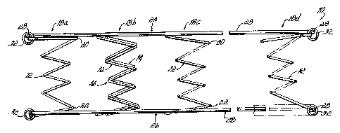
Fig. 5 illustrates an alternative embodiment of an
innerspring structure constructed in accordance with the principles
of the present invention. Innerspring structure 40 includes a
- 20 -
CA 02215019 1997-09-10
R'O 96/29524 PCTtUS96t03922
plurality of rows of coils, e.g., 42, 43 and 44 which extend
generally parallel to each other and are adjacent to each other to
form the innerspring structure 40. Each row 42, 43 and 44 of coils
includes coils formed from a continuous length of wire which is
generally wound to form a plurality of spaced coil pairs 45 or
coaxial coil unit pairs 54. The individual coils 45a, 45b of pairs 45
are connected together by Z-shaped interconnection segments 47
and 48 which are disposed sequentially and respectively first in the
upper or top plane 53 of the innerspring structure 40 and then
within the lower or bottom plane 52 of the innerspring structure
(see Figs. 4A and 5). Similarly, the individual coils 54a, 54b of
coaxial coil unit pairs 54 are connected together by Z-shaped
interconnection segments 56, 57 which are disposed sequentially
and respectively first in the top plan 53 and then in the bottom
plane 52 (see Figs. 4A and 5).
As best illustrated in Figs. 4A and 4B, each coil pair
45 or coil unit pair 54 comprises a first right handed coil 45a or coil
unit 54a offset from a second right handed coil 45b or coil unit
54b, preferably having the same number of turns, ar the same
pitch, as coil 45a or coil unit 54a. The axes 58 of the coils 45a of
each row, such as row 42, lie within a plane 50 which is parallel
-21 -
CA 02215019 1997-09-10
WO 96/29524 PCT/US96/03922
to, but spaced apart from, a second plane 51 within which lie the
axes 49 of the offset coils 45b. In a preferred embodiment, the
axes 58, 49 of adjacent coils 45a and adjacent coils 45b are
equidistant, with the axes being generally perpendicular to the top _
and bottom planes 52 and 53 of innerspring structure 40. The
coaxial coil unit 54a, 54b of row 43 are similarly spaced and
arranged in parallel planes wherein the axes 59, 60 are
perpendicular to top and bottom planes 52, 53.
The coaxial coil units 54a, 54b of row 43 are formed
in accordance with the principles of the invention by positioning
together a row of inner coils, such as coils 45a, 45b and a row of
outer coils designated 55a, 55b (see Figs. 4B and 5). As discussed
above, the reference to "inner" and "outer" coils is for reference
purposes only. Preferably, the inner coils 45a, 45b will generally
be identical to the outer coils 55a, 55b so that the two rows of -
inner and outer coils may be easily positioned together to form a
row of coaxial coil units 54a, 54b as discussed further hereinbelow
(see Fig. 4A).
Referring to Fig. 5, the innerspring structure 40 of the
invention will include rows of coils 42, 43, 44, wherein at least one
of the rows, e.g., 43, includes a reinforced coaxial coil unit 54a,
- 22 -
CA 02215019 1997-09-10
WO 96!29524 PCTlUS96JU3922
54b for making one or more sections of the structure 40 more firm
than other sections of the structure. Generally, an entire row
would be either single coils 45 or coaxial coil units 54, but half
rows of coaxial units or even a single coaxial unit may be used, if
desired. While Fig. 5 shows a single view for illustrative purposes,
it should be understood that a plurality of adjacent rows like row
43 might be utilized. Furthermore, all of the rows, whether single
coils or coaxial coil units, are preferably positioned and secured in a
similar fashion.
Fig. 4A illustrates a row of coaxial coil units
constructed in accordance with the principles of the present
invention. Specifically, row 43 comprises a plurality of adjacent
coaxial coil unit pairs 54 or coil units 54a, 54b, which are made up
of inner coil pairs 45, arranged as inner coils 45a and 45b, as well
as outer coil pairs 55, including individual outer coils 55a and 55b.
That is, each coaxial coil unit, e.g., 54a, will comprise of inner coil
45a, and an outer coil 55a. As mentioned, in a preferred
embodiment, the inner and outer coils 45a, 55a will generally have
the same shape and will generally be interchangeable.
Referring to Fig. 4B, row 43 of reinforced coaxial coil
units 54 is formed by positioning or intermeshing a row of outer
-23-
CA 02215019 1997-09-10
WO 96/29524 PCT/US96/03922
coils 55a, 55b, with a row of inner coils 45a, 45b. For example, a
first row 43a of inner coils 45a, 45b might be positioned as a row
of the innerspring structure 40. Next, a row 43b of outer coils
55a, 55b is positioned adjacent to the row 43a of inner coils 45a, _
45b to extend generally parallel thereto such that the inner coil
pairs 45 are aligned with the outer coil pairs 55. Each row 43a,
43b is made of a continuous pieces of wire so that the adjacent
coils are connected preferably by Z-shaped interconnection
segments. As mentioned, the row of outer coils 55a, 55b may be
formed in the same way in which the row of inner coils 45a, 45b is
formed, as the designation of inner and outer coils is made for the
purpose of reference to describe the unique construction of the
coaxial coil units discussed hereinabove. Preferably, the rows of
inner coils 45a, 45b and outer coils 55a, 55b are positioned such
that all the coils have the same winding direction as well as the
same orientation of the various Z-shaped interconnection wire
segments 47, 48. For consistency, the interconnection segments
of the row of outer coils 55a, 55b are also referenced as 47, 48.
In that way, as illustrated in Figs. 4A and 4B, when the adjacent
rows 43a, 43b of coils are pushed together to form a row 43 of
coaxial coil units 54 in accordance with the principles of the
- 24 -
CA 02215019 1997-09-10
R'O 96/29524 PCTlUS96103922
present invention, the individual rows 43a, 43b intermesh easily
together so that at least one inner coil, e.g., 45a, of each
reinforced coaxial coil unit 54a is wound or positioned coaxially
with respect to an outer coil 55a of the coaxial coil unit. When a
row 43 of coaxial coil units 54 is formed, the overlapping
interconnection segments 47, 48 are collectively designated as
segments 56, 57, respectively (see Figs. 4A and 5).
As will be appreciated from the following description,
the coil interconnection technique utilized to form the coils of the
innerspring unit 40 prevents adjacent coils from binding when
compressed even if they are not of hourglass configuration. Thus,
a variety of shapes may be employed such as hourglass or
potbellied, but the cylindrical shape illustrated is a preferred
embodiment.
Rows of reinforced coaxial coil units 54 might be
utilized at the sides of the innerspring structure 40 to extend
longitudinally therein for strengthening the mattress sides, which
receive a lot of pressure from persons sitting thereon. However, in
a preferred embodiment, the rows 43 of coaxial coil units 54 are
positioned to lie transverse in the innerspring structure 40 for
forming firmer sections at positions along the length of the
-25-
CA 02215019 1997-09-10
WO 96/29524 PCT/US96/03922
innerspring structure 40 and along the length of a mattress formed
from such an innerspring structure.
Preferably, each innerspring row, 42, 43 and 44 would
generally contain coils therein which are identical to every other
coil in the row and of the same twist direction and pitch (turns per
unit length). That is, each row is generally configured identical,
except rows of coaxial coil units 54 will comprise two rows of
inner and outer coils 45, 55 intermeshed together.
In the preferred embodiment of the invention, the
spacing between the axes 59, 60 of adjacent coils within a row 43
is the same as the spacing between axes 49, 58 of adjacent coils
in the other rows 42 and 44. The same positioning and spacing
would also hold true for two adjacent rows of single inner coil units
45a, 45b or two adjacent rows of coaxial coil units 54. Should a
coil pair 45a, 45b in row 42 be interconnected in the top plane 53
of the innerspring structure 40, the adjacent pair of coaxial coil
units 54a and 54b are also interconnected in the same top plane
53. This is best illustrated in Fig. 5 wherein in row 42, typical
adjacent coils 45a, 45b are interconnected by Z-shaped wire
segments 47 lying within the top innerspring plane 53, and the
adjacent pair of coaxial coil units 54a, 54b are interconnected by a
-26-
CA 02215019 1997-09-10
WO 9b129524 PCTlUS96103922
double Z-shaped wire segment 56 also lying in the same top plane
53 of the innerspring structure 40. This pattern is generally
repeated throughout the entire innerspring structure 40. Similarly,
the Z-shaped segments 48 in the bottom plane 52 of the
innerspring structure 40 lie in the same plane with the double
Z-shaped segments 57. This pattern is also repeated throughout
the innerspring structure 40. The result is that Z-shaped segments
in the top plane 53 are aligned in columnar fashion and similarly the
Z-shaped segments in the bottom plane 52 are also aligned in
columnar fashion. In other words, the Z-shaped segments 47, 56
and 48,57 are aligned both in rows and in columns in the top and
bottom planes 52, 53 of the innerspring structure 40.
In order to connect the adjacent rows of coils and coil
units, the rows 42, 43, 44 are first positioned so that the Z-shaped
segments which interconnect adjacent pairs of coils within each
row, such as segments 47, 48 for a pair of inner coils or single
coils 45a, 45b, or segments 56, 57 for a pair of coaxial coil units
54a, 54b, overlap the Z-shaped segments of the adjacent row of
coils or coil units. These overlapped portions or sections of the Z-
shaped segments are then connected or tied together by helical
wire connectors. Referring to Figs. 4A and 5, a first set of helical
-27-
CA 02215019 1997-09-10
WO 96/29524 PCT/US96/03922
wire connectors, herein designated 61, is disposed within the top
plane 53 of the innerspring structure 40 so as to join together
overlapped portions 62 of upper Z-shaped interconnection
segments, such as interconnection segments 47 and 56 as
illustrated in Fig. 7. Similarly, a second set of helical wire
connectors, herein designated 63, lie within the bottom plane 52 of
the innerspring structure 40 and serve to join together overlapped
portions 64 of lower Z-shaped interconnection segments, such as
48 and 57. In Fig. 5, the left side illustrates the lower plane 52 of
the innerspring structure to show the connector 63 and Z-shaped
segments 48. As evident in Fig. 4A, the length of each helical wire
connector is preferably approximately the same as the length of the
rows, and the helical wire connectors 61, 63 extend generally
parallel to the rows. As illustrated in Fig. 4A, the helical wire
connectors 61, 63 also connect together the row of adjacent inner
coils 45a, 45b, and the row of adjacent outer coils 55a, 55b. In
that way, the inner coils 45a, 45b are maintained generally coaxial
and intermeshed with the outer coils 55a, 55b to collectively form
the coaxial coil units 54a, 54b of the invention.
The assembly of the helical wire connectors to the
rows of continuous coils may be accomplished on an assembly
-28-
CA 02215019 1997-09-10
WO 96/29524 PC"TlUS961U3922
machine. In such a machine, the adjacent rows of coils are
positioned so that the sections 62, 64 of the adjacent Z-shaped
segments 47, 56 and 48, 57, respectively, are in overlapping
relationship. A helical wire is then rotated or screwed onto the
overlapping sections 62, 64 of the Z-shaped segments. In forming
a row of reinforced coaxial coil units 54 in accordance with the
principles of the present invention, a row of inner coils 45a, 45b
must be nested or positioned with a row of outer coils 55a, 55b
before any helical wire connectors 61, 63 are positioned over the
overlapping sections 62, 64. After completion of the threading of a
particular helical wire connector onto the overlapped sections 62,
64 of the Z-shaped segments, the now connected adjacent rows of
coils and/or coaxial coil units are indexed forwardly and another
pair of upper and lower helical wire connectors 61, 63, are
threaded over the next row of coils 45a, 45b, or the next row of
coaxial coil units 54a, 54b, depending upon the construction of the
next row. The process is repeated for the desired length of the
mattress, row upon row, after which the spring assembly is
removed from the machine.
Referring now to Fig. 7, it will be seen that the
diameters of the wire making up the helical wire connectors 61, 63
-29-
CA 02215019 1997-09-10
WO 96129524 PCT/US96/03922
are preferably approximately one-fourth ( 1 /4) the radius of the
overlapped sections 62, 64 of the Z-shaped segments. This
relationship of having the radius of the Z-shaped segments, over
which the helical wire connector 61, 63 is threaded, approximately
eight times the radius of the helical wire, has the effect of
permitting several rotations 65 of the helical wire connector to pass
through and lock adjacent overlapped sections together. So locked
or interconnected, the adjacent coils or coaxial coil units are free to
pivot relative to each other but are locked against relative
longitudinal or lateral movement. In other words, this relatively
small diameter helical coil, when used to lock the overlapped large
radius sections 62, 64 of the segments together, permits only
relative pivotal movement between the adjacent interconnected
coils.
Referring now to Fig. 6, each block 70 represents the
effective outline of a typical top plane Z-shaped interconnection
segment 47 in coil row 42. Similarly, each block 72 represents the
outline of a typical top plane Z-shaped interconnection segment 56
in row 43 containing the coaxial coil units 54a, 54b of the
invention. Each block 71 represents the outline of a typical bottom
plane Z-shaped interconnection segment 48 in coil row 42 and
- 30 -
CA 02215019 1997-09-10
WO 96/Z9524 PCTIUS96103922
each block 73 represents the outline of a typical bottom plane
Z-shaped interconnection segment 57 in coil row 43. Thus, as
apparent from the diagram in Fig. 6, the blocks 70, 72 and 71, 73
representing load supporting units. Each of these units 70, 72 and
71, 73 are overlapped such that the effect of the construction of
the innerspring structure 40 is a very densely packed innerspring
assembly with a relatively high count of coils. Furthermore, coil
row 43 provides load bearing units which are firmer, stronger and
more supportive according to the description of the invention.
Referring now to Figs. 5 and 7, it will be noted that
the several rotations 65 of the helical wire connectors 61, 63
which pass around and lock adjacent overlapped coil segments 62,
64 are all centered in a common transverse plane 75. It will be
further noted that this plane 75 passes through the vertical axes
58, 59 or 49, 60 of all of the coils or coaxial coil units contained in
a transverse column. Consequently, each coil or coil unit of a row
is connected to two coils or coaxial coil units of the adjacent rows
by several rotations 65 of the helical connectors 61, 63 the center
planes 75 which are located in a diametrical plane defined by the
vertical axes 58, 59 or 49, 60 of the coils or coil units. This
location of the axes of the coils or coil units relative to the location
-31 -
CA 02215019 1997-09-10
WU 96/29524 PCT/US96/03922
and shape of the overlapped and connected segments 62, 64 has
been found to prevent lateral deflection or distortion of the coils
when the coils are fully compressed.
Once the various rows and coils are assembled into
the innerspring structure 40 of the invention, a border wire, like
that shown in Figs. 1-3, might be utilized to finish the structure.
To that end, the border wire is secured to the outer peripheral coils
of the adjacent rows, such as by a helical coil 32. Other
connecting mechanisms for fixing the border wire to the innerspring
structure 40 might also be utilized.
Figs. 8 and 9 illustrate another embodiment of the
invention in the application made with a continuous coil spring
product similar to those illustrated in Figs. 4A-7. The construction
is illustrated diagrammatically on the top plan view of Fig. 8. In
1 5 general, the spring assembly of Figs. 8 and 9 is identical to the
spring assembly of Figs. 4A-7, except that the coils are positioned
with the interconnecting Z-shaped segments such that the vertical
axes of all of the coils of a single row are located in the same
vertical plane 80, rather than alternatively staggered in two
different planes as shown in Figs. 4A-7.
- 32 -
CA 02215019 1997-09-10
R'O 96/29524 PCTlUS96103922
The Z-shaped segments, rather than extending
outwardly from one side only of each coil extend outwardly beyond
both sides of each coil so that this construction has the same
_ advantages of the embodiments of the Figs. 4A-7, and it minimizes
or eliminates any tendency of the coils to overlap or contact
adjacent convolutions of the same coil. Specifically, in this
embodiment each row of coils 82, 84, 86 is formed from a
continuous length of wire and each wire forms a plurality of spaced
coil pairs 88 interconnected by substantially Z-shaped wire
segments 89 disposed in the top plane of the innerspring structure
90. In the bottom planes, substantially Z-shaped wire segments 91
interconnect adjacent coil pairs 88 of the innerspring structure 90.
In accordance with the principles of the present
invention, each innerspring 90 will preferably contain at least one
row 84 of coaxial coil pairs 92. Each pair 92 of coils 92a, 92b will
comprise a pair of inner coils 88a, 88b, and a pair of outer coils
94a, 94b which are preferably positioned and intermeshed together
by the method described hereinabove with respect to Figs. 4A-7.
That is, rows of inner coils 88a, 88b are pushed together with
rows of outer coils 94a, 94b to form coaxial coil units in
accordance with the present invention which are collectively
-33-
CA 02215019 1997-09-10
WU 96/29524 PCT/US96/03922
referred to as coil units 92a, 92b. That is, for example, coil unit
92a will include an inner coil 88a, and an outer coil 94a and each
coil unit 92b will include an inner coil 88b and an outer coil 94b.
The coil units 92a, 92b are connected by Z-shaped interconnected
segments 93, 95 in the top and bottom planes, respectively.
Each coil pair 88, 92 comprises a first right handed
coil 88a or coil unit 92a offset from a second right hand coil 88b or
coil unit 92b preferably having the same number of turns as coil
88a or coil unit 92a, respectively. However, the axes of coils 88a,
88b and coil units 92a, 92b lie within the same plane 80 containing
the axes of the adjacent coils and coil units. While preferably, the
coils of each row generally have the same diameter twist direction
and pitch, alternative twist directions diameters or pitches may still
be utilized in practicing the present invention.
In the embodiment of Figs. 8 and 9, the corners of the
interconnecting Z-shaped segments are both located outwardly
from the circumference of the coils 88 and coils units 92 in both
the top and bottom planes of the innerspring structure 90. The
outward spacing of the Z-shaped segments facilitates
interconnection of the overlapped portions of the Z-shaped
segments by helical spring connectors 98, as discussed above. ,
- 34 -
CA 02215019 1997-09-10
WO 96/29524 PCTIUS96I03922
Referring to Fig. 8, it will be noted that: several
rotations 100 of the helical lacing wire connector 913 pass around
- and lock adjacent overlapped segments 102 of the coils to coils or
coil units of the adjacent rows. It will further be noted that the Z-
shaped segments are all shaped and positioned so that the locked,
overlapped segments 102 are all in a common transverse plane 104
which passes through the axes 106 of all the coils and coaxial coil
units contained in a transverse column. Consequently, each coil or
coaxial coil unit is connected to two other coils or coil units of
adjacent rows by connectors 100 having centers 104 which are
located is a diametrical plane of the coils and coil units as defined
by the axes 106.
Referring now to Fig. 9, each block 1 10 represents the
effective outline of a typical top plane Z-shaped interconnection
segment 89. Similarly, each block 1 12 represents the outline of a
typical top plane Z-shaped interconnection segment 93 in the row
containing the coaxial coil units 92a, 92b of the invention. Each
block 1 1 1 represents the outline of a typical bottom plane Z-shaped
interconnection segment 91 and each block 1 13 represents the
outline of a typical bottom plane Z-shaped interconnection
segment 95. Thus, as apparent from the diagram in Fig. 9, the
-35- '
CA 02215019 1997-09-10
WO 96/29524 PCT/US96/03922
blocks 1 10, 1 12 and 1 1 1, 1 13 representing load supporting units.
Each of these units 1 10, 1 12 and 1 1 1, 1 13 are overlapped such
that the effect of the construction of the innerspring structure of -
Figure 9 is a very densely packed innerspring assembly with a
relatively high count of coils. Furthermore, the coil rows of Figure
9 provide load bearing units which are firmer, stronger and more
supportive according to the description of the invention.
Several different coil configurations have been
illustrated for practicing the present invention; however, in addition
to the individual coils and continuous coil products illustrated, other
coil products might also be utilized. In accordance with the
principles of the invention, Bonnell coils might be utilized, as well
as knotted coils, e.g., offset coils, and unknotted coils.
While the present invention has been illustrated by a
description of various embodiments and while these embodiments
have been described in considerable detail, it is not the intention of
the applicants to restrict or in any way limit the scope of the
appended claims to such detail. Additional advantages and
modifications will readily appear to those skilled in the art. The
invention in its broader aspects is therefore not limited to the
specific details, representative apparatus and method, and ,
' - 36 -
CA 02215019 1997-09-10
WO 9b/29524 PC'FIUS96103922
illustrative example shown and described. Accordingly, departures
may be made from such details without departing from the spirit or
scope of applicant's general inventive concept.
What is claimed is:
-37-