Note : Les descriptions sont présentées dans la langue officielle dans laquelle elles ont été soumises.
CA 0221~026 1997-09-lO
WO 96/30217 PCI'INZ96/00021
MACHINE-READABLE LABEL
FIELD OF THE INVENTION
This invention relates to the field of identification, more particularly to identifying
objects by means of labels, and most particularly to labels which are adapted for
reading by machine (that is, a digital cc,nl~u
BACKGROUND
There is a need for an identifying label for use in tracking merchandise during shipping
or manufacture. An optical or other type of "no-touch" label is preferred, and it should
20 be capable of use in applications where:-
(a) image capture is carried out in possibly adverse circumstances, such as outdoors or
where part of the label may be obscured, lost, or cont~min~tt-~l, curled up, or in shade,
or the label may be presented obliquely or unsharply,
(b) the exact position and orientation of the label is not defined,
25 (c) there may be a plurality or large number of labels in any one captured image,
(d) a high degree of accuracy in reading the label is required, and
(e) labels may be out of reach to a bar-code scanner or the like.
Furthermore, where, in particular, there is a need to use a cheap and relatively30 low-resolution camera every available part of the label should be covered with data
markings that are as large as possible, given that a relatively small label such as one 50
mm across is highly preferred.
A particular application is in tracking cut tree trunks (lumber) from felling to export. At
35 the forest site where logs are accumulated before loading onto a truck, it is customary in
some forests to attach a pre-printed bar-coded label to the cut end of the trunk in order
CA 0221~026 1997-09-10
WO 96/30217 PCI'INZ96100021
-- 2 --
to identify the tree, which is separately described in relation to ownership, volume,
quality, type, and the like. The bar-code and the associated data are later entered into a
management computer database. A barcode is not easy to read later, when for example
S the log may be one of many on a moving truck, or in a cradle being loaded onto a ship.
There is a need to read labels of this type more easily.
OBJECT
It is an object of the present invention to provide an improved identification label of
10 machine-readable form, and/or an improved set of instructions for reading labels of this
type, or to at least provide the public with a useful choice.
STA~E~ENT OF T~; INV~NTION
The various aspects of the invention can be ascertained from the claims. For example in
15 one aspect the invention provides a machine-readable label as defined in claim 1, in
another aspect the invention provides a set of labels as defined in claim 4 or in another
aspect the invention provides a method of identifying one or more items at a site as
defined in claim 9.
20 In another aspect the invention comprises a computer-readable label or symbol for
identification purposes, comprising a matrix of computer-readable indicia; each
indicium containing at least one element of readable information, and in which the
matrix of information includes an error-correcting code and at least one indicium serves
as a locator to provide a reading machine or computer with the location of the
25 remainder of the matrix.
Preferably the error-correction code is a cyclic code capable of coping with individual
bit errors.
30 More preferably the error-correction code is the BCH code, or a derivative of it, such as
a shortened BCH code.
Preferably the label is optically readable and accordingly each of the computer-readable
indicia is provided with one of an optically detectable, defined range of specific levels
35 of brightness.
CA 0221~026 1997-09-10
WO 96/30217 PCr/NZ96/00021
-- 3 --
Preferably the label is capable of scattering or reflecting light, and accordingly
brightness levels are equivalent to reflectance levels.
5 Accordingly the label is, for the purpose of reading, capable of being illllmin~tçtl by a
transducer-compatible source of electromagnetic radiation.
Preferably the resolution or density of pixels in the image-collecting device of the
reading m~hine is such that an area of at least three by three of the sampling elements
10 used by the reading m~chine is provided to at least partially cover each indicium.
Preferably the label is ~ul~oullded on at least one side by an outer edge composed of a
relatively bright surface which is preferably at least three s~mpling units wide.
IS Preferably this surface corresponds to the white level of the grey scale.
Preferably at least two sets of indicia serve as locators.
Preferably the locators are, on detection, capable of providing a reading machine with
20 information defining the location (that is, position and/or orientation) of the remainder
of the matrix.
Preferably each such locating indicium comprises at least one matrix element
surrounded by a field of contrasting matrix elements.
Optionally the matrix element or elements of any one locating indicium may also be
used to indicate a step or steps of a scale of brightnesses.
Optionally no locating indicia are used; in which case the reading machine attempts to
30 correctly decode the matrix of indicia by a process of repeated trials at different
locations and orientations.
Preferably each cell of the matrix of computer-readable indicia is optically detectable
and preferably each indicium has a determined reflectance.
Preferably each cell of the matrix of computer-readable indicia is provided with one of
.
CA 0221~026 1997-09-10
WO 96/30217 PCI-INZ96100021
--4--
two contrasting reflectances.
Optionally each cell of the matrix of computer-readable indicia is provided with one of
S more than two contrasting reflectances.
Optionally, therefore, any cell may be composed of a material having an intermediate
level of reflectance.
10 Preferably the or each intermediate level is evenly spaced between the brightest and
darkest levels.
Alternatively the optical characteristics of a range of cells providing dirre~ t levels in
a scale may include a type of reflectance which is perceived as a contrasting level by an
15 array of sensors comprising more than one set, each set having a response pattern
dependent in a different way on the characteristics of the reflected energy.
Optionally a full range of colours may be used.
20 Optionally each cell may comprise an array of a plurality of dots of one contrasting
surface placed upon a substrate of another contrasting surface in variable proportions in
order to simulate intermediate levels of reflectance.
Preferably each cell is large enough that when the anticipated environmental "noise" is
25 superimposed on it, the preferred error correction process sees the interference as
random noise rather than burst noise affecting adjacent pixels.
Preferably the matrix of information-carrying indicia is read in a consistent order so that
in use each indicium comprises a predetermined part of an array of information,
30 incorporating means for detecting and correcting any errors.
Preferably the error-correcting code is a shortened BCH code.
Optionally the error~orrecting code is a full BCH code.
Optionally any other error-correcting code capable of replacing the intended
CA 0221~026 1997-09-10
WO 96/30217 PCI'~NZ96100021
_ S _
information in the event of corruption of cell brightness may be used.
Preferably a printing device is provided with a generator of printable patterns according
5 to the ternary shortened BCH code information protocol of this invention so that a
series of unique labels, compatible with the computer reading process, can be
generated.
A preferred generator of printable patterns comprises a computer capable of receiving a
10 string of characters and converting them into a matrix of cells together witherror-correcting code, as described previously in this section.
Optionally the generator of printable patterns may provide a translation of the design
and error-correcting codes into a language or form suitable for use in a printer to
15 actually produce the image.
A preferred language is "Postscript".
A preferred label comprises at least a damage-resistant substrate and a display surface
capable of holding the indicia of the label.
Preferably the label also includes bar-code and human-readable indicia.
In another broad aspect the invention includes a reading machine which is capable from
time to time of capturing an image of a field of view, which may include one or more
25 labels, and holding the image internally in a form comprising a matrix of sampled
points each of which may be mapped to a corresponding point within the image.
Preferably an illumination device is provided to flood a field of view with
electromagnetic radiation at least during the period of capturing the image.
Optionally a scanning illumination device may be used to ilhlmi~tto a field of view, in
a sequential fashion.
Preferably the reading machine includes a solid-state camera electrically coupled to at
35 least one addressable memory plane accessible to a digital computer operating under a
stored prograrn, and includes an output interface.
.
CA 0221~026 1997-09-10
WO 96130217 PCI'INZ96/00021
-- 6 --
Preferably the output from the reading machine comprises the information contained
within the or each label.
5 Optionally the reading machine may be physically separated into an image collection
portion and an image analysis portion, separated by a commllnic~tions link.
Optionally the reading machine may be non-optical; that is, it may use microwaveradiation or sound (preferably ultrasonic sound) to illllmin~te a field and collect
10 radiation from discrete sites of the field preferably using phased and/or time-controlled
illumin~tion, together with a suitable detector.
Preferably, then, the symbol and its indicia shall preferably exhibit varying yet
controlled degrees of reflectance to the non-optical illllmin~tion.
Preferably the reading machine locates the position and orientation of any one label in
an image containing one or more labels by first detecting the characteristic appearance
of a set of one or more accompanying locators.
20 Preferably it then reads the located data cell matrix.
Preferably the reading machine determines the actual reflectance of the label by a
process of determining the most reflective and the least reflective portions and scaling
the apparent reflectance accordingly.
Preferably the reading machine compensates for uneven regional ilhlmin~tion on any
one label by ex~mining the a~palcnt brightness of the outer edge and compensating the
apparent brightness of the adjacent matrix accordingly.
30 Preferably the reading machine shall be capable of determining the relative levels of the
steps of a grey or colour scale, if any, using the range of reflectances included within
locating indicia, so that in use any indicium can be assigned to a corresponding and
known level in the scale of reflectances in use.
35 Optionally, the reading machine may be capable of locating the matrix of data cells
without the aid of the locators, and in that case it would carry out a series of trial
CA 0221~026 1997-09-10
WO 96/30217 PCI'~NZ96/00021
- 7 -
readings until it detected that a reading was valid.
DRAWINGS
5 The following is a description of a preferred form of the invention, given by way of
example only, with reference to the accompanying diagrams.
Fi~ 1: is an illustration of a co~ ulel-readable symbol of the present invention.
Fi~ 2: is an illustration of a combined human-readable symbol array, a bar-code
array, and a computer-readable symbol upon a printed label of the
present invention, ready for use.
Fi~ 3 is a block diagram of the processes of the present invention.
Fig 4 is a grey-scale rendition showing the software analysis process for a
symbol according to the present invention.
PREEl~RRED EMBODIMENT
20 This invention comprises a computer-readable label or symbol for identification
purposes. This generally optical label has been optimised in particular for applications
where (although at the same time the label shall be as small as possible):-
(a) image capture is carried out in possibly adverse circumstances, such as outdoors
or where part of the label may be obscured, lost, cont~min~ted, lost in shade,
curled up, or the label is presented obliquely or unsharply,
(b) the exact position and orientation of the label is not defined,
(c) there may be a plurality or large number of labels in any one captured image,
and
(d) a high degree of accuracy in reading the label is required.
In one example application these labels are used to identify tree trunks, or logs. Eachpre-printed label (which simply serves as a unique identifier) is attached to the cut end
of a log and an accompanying bar-code is scanned or the alphanumeric characters are
noted down. Other data such as quality and ownership are also noted and stored in a
35 mastcr database along with the corresponding label number, so that as the log passes
through a series of stations it may be identified and (for example) its ownership may be
CA 0221~026 1997-09-10
WO 96/30217 PCI~/NZ96100021
-- 8 --
established. Typically these stations are along a transport chain such as trucking, then
shipping, then trucking to a destination sawlrull.
S At any one of these stations there may be a requirement to read the labels on a bundle
of logs in an efficient, quick, safe manner and report their presence at a certain time and
place to a management system which includes the master database. Therefore we have
developed a camera system and image analysis procedure capable of snapping a picture
of the ends of a bundle of logs while held on a truck or in a cradle, detecting all labels,
decoding the data, and passing it to the management system. On a wharf, logs areusually placed in a cradle by a lifting machine. A sling is passed around the cradled
logs, and they are lifted into the ship. While the logs are in the cradle, they can be
photographed.
One main requirement is an error rate (specifically a bad label report error, in which a
wrong number is unknowingly delivered), of no more than 1 in 100,000 labels. Themost harm is done to the database by incorrect information, rather than by providing a
blank. Another conflicting requirement is to use a low-cost and hence low-resolution
digital camera, possibly with an imperfect CCD chip, to capture images. A further
conflicting requirement is tolerance to damaged or obscured or dirty labels. Andanother requirement is tolerance to variable levels of lighting.
Therefore there is a need to design a label in which the best use is made of the display
area of the label; given that human-readable indicia, and a bar-code, are also required.
There is a need to make it plain to the reading computer or machine when an error
exists, and to provide correction means if one does exist.
We have provided a 29-bit number, with 17 further bits available for error correction,
by using (in the example label) a 6 x 7 matrix of squares, each of which may be
coloured white, grey, or black. Each cell is a minimum element of the information
carried by the label. This label uses a ternary number base. Some of the 56 cells are
reserved, in exarnple labels, for locators (see later) and some are reserved for the site of
a conventional barcode. Fig 2 shows an example label as it would be used, in which the
"ternary BCH" code 100 of the present invention, together with corresponding
alphanumeric descriptors (202, 207), an owner's name and/or logo 206, and a
corresponding barcode 203 are provided. BCH stands for a preferred error correction
CA 0221~026 1997-09-10
WO 96130217 PCI'INZ96/00021
_ 9 _
procedure. 205 indicates optional descriptors. 204 is an optional tear line for sep~dtillg
part of the label for separate processing. This label has a border 201, merely
representing the edge of the paper or like substrate for the symbols.
Fig 1 shows the actual data cell section itself. The actual label 100 has no actual border
or boundary, though preferably a space at least three sampling units wide which is
preferably in the maximum reflective state (i.e. white) is provided about the entire bar
code for reconstructing detailed illumination variation, if required. Each unit cell
(101,105, 108, 109) is shown here as a dark grey, a speckled, or a white square. ~We
cannot display squares as black in this specification owing to restrictions on patent
drawings - no solid blacks are allowed). Nevertheless, in printed labels the darkest
portions are actually black (although as will be elaborated later, a ternary system having
three grey levels need not be stretched to either limit of reflectance).
In Fig 1, the locators are shown as cells 101, 102, 103 and 104 together with the
surrounding contrasting space such as the space 107. This space is reserved. The data
matrix 106 may extend about the locators. The un-used space between the locators 103
and 104 is reserved in our example label for a bar code 203.
In our trials, camera noise appears to be about + or - S units in a 256-step level, and
combining this scatter (which may represent noise or internal compensation) withadverse illllmin~tion effects in the outside environment leads us to conclude that more
than a ternary encoding system would be too likely to result in errors. Of course, in a
25 more controlled imaging situation a greater than ternary encoding system may be
adequate. We prefer to err on the side of caution. We see base~ or base-S or more cells
as being too easily prone to higher errors in our example application, at least, even
though the amount of information that can be stored rises markedly as the number of
levels goes up. Future versions of this labels may even cover 256 steps in each of red
30 and green and blue channels giving 22~1 combinations per cell, if printing and reading
technology (to say nothing of fading inks in daylight) allow such resolution in a
cost-effective package. A machine version of human-type colour with at least twochannels, and perhaps extending to infra-red or ultra-violet) in any one cell, may be
used. For the present embodiment, a ternary scale made by black "ink" is preferred.
The label is sized with respect to the image capture device and interrnediate factors
CA 0221~026 1997-09-10
WO 96/30217 PCT/NZ96/00021
- 10-
(distances, focusing elements and the like) so that each cell at least partially covers at
least three pixels and preferably has a spatial resolution corresponding to four pixels
per cell along both a horizontal and a vertical line, (or sampling elements, applicable if
S a scanner and A-D converter is used instead) which are internal to the reading m~hint~.
This size requirement allows for rejection of pixels that overlap a transition in the label
or possibly their incoIporation in more sophisticated analysis, or in label reconstruction
should a label image be compromised. (It is not generally possible to repeat a
photograph in the target environment). It also allows for some latitude in focusing the
10 label onto the image plane of the sensor, or movement smearing or the like. It also
allows some latitude for use of cameras that have defects in their CCD arrays. Such
defects are well known and include isolated cell defects, row defects, and/or column
defects. (Defect-free cameras exist, but dust spots or crystal imperfections can arise
from time to time during manufacture and so defect-free cameras command premium
15 prices).
The external space (see later) is particularly used to determine gradations of
illumination over any one label. Ie should preferably be at least one matrix square (or
three pixels of the reading machine's camera) wide, although conveniently it can be
20 wider.
LOCATORS
We prefer to use least two, and preferably four sets of indicia (such as 101 with 107 to
25 serve as locators. Each set or locating indicium comprises at least one cell or matrix
element 101 surrounded by a field of contrasting matrix elements 107; and generally the
surrounding field is white. We make one pair of adjacent locators 103, 104 assume the
black level, and the other two assume the grey level. The software is able to determine
the intended reflectance of any cell once it can measure the actual brightness of the
30 locators and their surrounding fields, and thereby compensate for variations in lighting
or exposure that may otherwise detract from accuracy.
Preferably the locators are, on detection, capable of providing a reading machine with
inforrnation defining the location (that is, position and/or orientation) of the remainder
35 of the matrix. The software uses sub-pixel accuracy to determine locator position.
CA 0221~026 1997-09-10
WO 96/30217 PCTINZ96/00021
Optionally no locating indicia are used; in that case the reading machine attempts to
make sense of a postulated matrix of cells by a process of repeated trials at different
locations and orientations.
BCH CODE
The preferred BCH (Bose-Chaudhuri-Hocquenghem) code family, developed in 19~9
and 1960, can be regarded as a generalised form of ~mming codes for correcting
10 multiple errors. They are cyclic, constructive codes suitable for communication
channels in which errors affect successive symbols independently. The well-knownReed-Solomon codes appear to be a special case of BCH codes.
~ We have developed a shortened (47,29) length BCH code to cope with our preferred
rectangular array of data cells (in 100) containing 30 ternary ~3-level) cell blocks,
which represent 47 bits of binary data. This BCH code has a guaranteed minimum
distance of 7, so that at least 7 bits would have to be in error before a code would be
miscategorised. The shortened code does not cover all 26 million possible variations in
number, yet it is adequate to meet the desired level of accuracy. We use 5 (binary) bits
20 for the alphabetic character and 24 bits for the number, fitted into the 47 bit BCH
address space - in a spaced-apart format.
Of course, in some circumstances an error-correcting code may not be necessary. In our
application it enhances the reliability of reading damaged labels, yet allows the overall
25 label size to be smaller than if other methods, such as data duplication, were used.
We also lay our matrix out so that straight lines are minimiced; we use the so-called
Knight's Walk strategy to lay out the cells.
30 A COMPLETE SYSTEM
Fig 3 shows a data processing system 300 for identifying logs. A device 301 to generate
preferably unique pattems of "ternary BCH" symbols including data, an error code, and
locators, with other label material (see Fig 2) according to this invention sends data to a
35 printer 302. A preferred printer language is "Postscript". The printer may be located at a
forest site, or may simply prepare a large stack of labels for field use. 303 represents a
CA 0221~026 1997-09-10
WO 96/30217 PCI~/NZ96/00021
- 12-
stack of labelled logs, in front of a camera 304 which passes a digital signal to a Wide
Area Network interface 305, which transmits the signal to a receiver 306, then to an
image analysing computer 307. This reproduces the data 308 originally contained in the
ternary BCH symbols.
PRIN7rING
Preferably, there shall be a device 301 to generate data cell rnatrices based on the
preferred ternary BCH code placed at the site where labels are printed, so that a series
of unique labels can be generated. A computer-driven printing machine 302 is
preferred, and one kind is a conventional laser printer applying fused toner to a
preferably damage-resistant paper, while another preferred kind is a "Printronics"
L5024" type that uses an xenon flashlamp to fuse toner onto a substrate which can
include vinyl, a material that has a melting point lower than the temperature used in
normal laser printers. This machine has the additional benefit that its blacks are matt.
Shiny blacks appear white to a camera with a side-mounted flash lamp. Optionally each
cell as printed may comprise an array of a plurality of dots of one contrasting surface
placed upon a substrate of another contrasting surface in variable proportions in order to
simlllate intermediate levels of reflectance; a grey level. We use dots that are about 1
mm square, as shown in Fig 1 at 101, for example. As the labels will be illuminated
substantially perpendicularly along the optical axis, the blacks should preferably be
matt and not reflective.
THE CAMERA
We require a portable data-gathering station that can rove about a transport site such as
a wharf; an individual wearing a backpack and holding the camera is envisaged. We
prefer to use a battery-driven hand-held solid-state camera 304 containing a CCD chip
with an X-Y array of for example 1000 pixels high by 1500 across. A "KODAK" DCS
420 camera (IR version) with 1536 x 1024 pixels is in use. A higher resolution camera
would of course have advantages, but cameras of the preferred type are available as
off-the-shelf items from several suppliers, and minimal or (by the use of activecorrection) minirnised-defect examples may be found. This camera is assisted by a
conventional flashgun, though we prefer to use a flash of infra-red light so that (among
other reasons) other people in the yard are not distracted or blinded by the use of the
~ ,~ . = . . _
CA 0221~026 1997-09-10
WO 96/30217 PCI~ 96100021
- 13-
flash, especially at night. Some people are driving 50-tonne log-carrying trucks near the
cradles being photographed.
5 We prefer to use a Wratten 25 filter on the camera, preferably coupled with a filter to
block infra-red light beyond about 800 nm; thus admitting the 550-900 nm range to the
silicon-based CCD device. This red filter allows aiming by the operator. Red or
infra-red light may enhance the contrast between the labels and the background of wood
which is the usual background. Ideally, a narrow-band source and a narrow-band filter
10 over the camera lens would minimise the contribution of ambient light to the image,
and we are experimenting suitable filters. Because the camera is expected to make at
least 240 pictures in a four-hour spell between battery changes it is not practical to use a
very bright flash (with heavy batteries) to overcome ambient light.
15 The camera passes digital image data out for processing as soon as one image has been
collected, although as supplied it includes a hard-disk storage device to store about 60 -
70 images. A preferred camera lens is an 18 mm fisheye lens, as this allows the
operator to approach the cradle or other holder of logs and illuminate it well with the
flash lamp, and minimises focus errors especially those caused by an irregular or
20 uneven object plane. The CCD sensitive area comprises a small central part (about 1~ x
20 mm) of the 24 x 36 mm image plane of the modified "Nikon" camera and a normalor telephoto lens would necessitate too great a working distance for this application.
A reading device which scans an area with a pencil beam from a laser may be used in
25 some applications, but the total reading time would tend to be too great for a hand-held
device. It may be more suitable for a more controlled environment, such as a fixed
camera platform reading labels on steadily moving objects such as railway wagons.
Non-optical images may be used in some applications and for example it might be
30 possible to read suitably created labels inside other structures using microwave or
ultrasonic holographic techniques. This may be useful for finding labelled sheets of
paper filed within a stack, for example in an office.
RELAYING DATA TO THE IMAGE PROCESS~G COMPUT~ER
The camera output carrying the image does not (in the preferred embodiment) go
CA 0221~026 1997-09-10
WO 96t30217 PCIINZ96/00021
- 14-
directly to a memory plane for image analysis; there is an intermediate data
transmission step. The camera output may be coupled with other information. For
example we digitally encode some variables such as backpack battery condition and
5 transmit this to the base station. The ship and the hold of the ship into which logs from
that cradle are being loaded may be written on the cradle so that that data is also
recorded. As the image processing co~ uL~l is relatively large and complex it is housed
remotely and data is sent to it over a "Novell" wireless wide-area network system 305
Op~;ldlillg at around 2.3 GHz with a 200 Kb/second trancmi~cion rate. The image data is
10 (at present) an uncompressed TIFF format file and each image is about 1.5 Mbytes in
size, so the transmission time is about 8 seconds. The camera is connected to a
dedicated portable PC constructed in a small case. The case, with batteries, is placed in
a backpack. It runs on 12 volts, and is ~ltted with a self-booting prograrn that downloads
its operating programs over the network, then transmits image data together with some
15 additional information, such as the log count and computer and camera batterycondition, to a base station 306. The log count may be independent, perhaps the
operator uses a "sheep counter" or perhaps a stick-shaped device with a counter that
also squirts a marker like paint on a log as it is pressed against it.
20 In time we may develop the image processing computer to such an extent that ~t is
included with the camera and this would have the advantage of more quickly reporting
an inadequate photograph.
We may also use software image compression before transmission if it is warranted.
25 The "Novell" networking software takes care of error situations.
IMAGE PROCESSING COMPUTER
At present we use a "Digital Equipment Corporation" Alpha "AXP" computer for
30 image analysis; to extract information corresponding to the labels that may be present
within a field of view. This computer 307 completes the process within about 5.5seconds, while making various reports and drawing lines upon a displayed image at the
same time. Lists and traces for debugging purposes are available. A production version
~ would not normally offer an operator any opportunity for intervention, and would
35 therefore be faster. We prefer to compile the same program with different switches so
that we can develop special needs for a particular application and then make a
CA 0221~026 1997-09-10
WO 96/30217 PCI'INZ96/00021
- 15-
production version from the same software.
Input to this co~ ler is via a preferred "Novell" network and the output 308 may also
5 be sent through a network or by modem to a management database located at somedistant site. One image processing computer can handle images from several cameras in
use at the same transport yard, which may be a dock where several cradles of logs are
being loaded at one time.
10 SOFTVVARE
Assuming that an image has been loaded as a copy of the camera pixel array (size from
about 1024 x 1024 to about 4096 x 4096 bytes; preferably 1024 high by 1536 wide), the
software that distills information from that image can best be described as a series of
15 steps.
We assume that any valid labels will be of a certain approximate size, wherein the
image of each blob is about 4 pixels by 4 pixels, in order to include an entire cradle of
logs in one field of view. Camera operators are told to stand at about a certain distance
20 from the subject. It will be clear that other sizes can be accommodated by either having
the program use a scanning approach, perhaps starting with the last suitable "zoom
factor" or by programming in a different constant zoom factor. Our preferred camera
(having a limited number (1536) of image pixels across) gives an about 3 mm square
(as referred to the label) pixel size.
A larger number of camera pixels will provide (a) smaller labels, or (b) more precise
reading with more redundancy of data, or (c) more logs on a cradle, but on the other
hand 1.5 Mb of data is quicker to transmit and analyse than 16 or even 4 Mb.
30 The description below assumes that four locators are used on each label. It will be
evident that minor changes to the algorithm will accommodate other numbers of
locators.
It will also be evident that there is no search for a border as such as a way of locating
35 labels. Some prior art computer-readable labels rely on borders for location, orientation,
and sometimes cell spacing information. The only occasion on which the label edge is
CA 0221~026 1997-09-10
WO 96/30217 PCI'INZ96/00021
- 16-
used under our present system is when variations in lighting over the label surface is
examined. The locators serve to define the position and orientation of the
accompanying information.
1. The picture (which may optionally be reconstructed at this point if a defect is
recognised) is scanned across perhaps every scan line or row to locate dark
blobs of about the right size and edge characteristics. The XY co-ordinates of
each located blob are saved.
In more detail, a suitable dark blob is one in which the brightness declines from
a lighter background level to a darker in-blob level, and remains at the darker
level for one or two pixels at least, and then rises at about the same rate. A graph
of displacement/ brightness would have a trapezoidal form. The computer may
"hunt" by comparing adjacent pixels to find the minimum brightness point to get
a first approximation to an x,y point.
The program is quite flexible at this stage about the actual value of a light area
or a dark blob, so that varying lighting conditions within a single image can bedealt with. For example a short log bearing a label might be recessed from
normal sized logs, so its label would be apparently much darker than the others.
.
2. The actual centre of each blob is located to sub-pixel accuracy by a
centroid-finding procedure in which the mean of the displacement x density
product is averaged, in both directions. At this stage some further blob
validation is done (such as symmetry, for asymmetrical dark blobs are not like
the preferred locators, aa contrasting (usually white) locator border, and the
like). An accurate centre determination assists in recovering the data from the
central pixels of each cell of the information matrix.
3. Neighbouring blobs are now located and attempts are made to form "pairs" -
blobs at about the right distance from each other that comply with the expected
distances between locators.
35 4. "Triplets" of blobs where the outer blobs are at right angles (approximately) to a
centre blob are searched for.
CA 0221~026 1997-09-10
WO 96/30217 PCI'INZ96/00021
- 17-
5. Rectangles are then formed by trying to find a fourth blob at about the right
position from both the outer blobs. Note that we are tolerant of actual rectangle
accuracy; it would be more correct to call the forrned areas quadrilaterals. Lens
S errors, labels which are not perpendicular to the optical axis, and some damaged
labels (for example) will give rise to valid, ~ough non-rectangular sets of data.
6. Unique rectangles are then formed and a list is stored, while apparently
overlapping rect~ngles and other such errors are put into a "too-hard" stack.
7. Taking each rectangle one by one, a data area is set up within it and the data
cells are categorised. Particularly relying on the locators' density values and that
of the neighbouring white area, a scale of what is black (i.e. falling within a
certain range of densities), what is grey (a distinct and higher range), and what
is white (another distinct and even higher range) is constructed.
8. The data cells are then recategorised. Here, a partially shadowed label will
become evident. These are also put into a "too-hard" stack.
20 9. The data cells are read as ternary information in a specific order, after
orientation has been established by e~mining the relative darkness levels of thelocators, which indicate orientation.
10. The "easy label" data cell data is then passed to a decoder, which extracts the
actual ternary information, applies error correction, and reports the information
in the usual decimal form. At this stage, error conditions such as a splash of
mud or the like are detected and corrected through action of the BCH error
check. In an exarnple:
Data sent to decoder: 1011001 002200 0200220 2211011 0220011 1011021.
Error check reveals: 2211011 should be 2111011 and alters that ternary bit.
Perhaps a spot of mud made the cell look darker.
11. The program now reverts to its "too-hard" stack and attempts to recategorise the
~ data cells. Some of the contents of this stack may not be labels at all - just
coincidentally similar sets of pixels. Partially shaded labels are dealt with by"walking" around the edge, which is always a white strip, and collecting spot
., ., , ~ _ . . . , _ . _ _ . . _ . _ _ _ _~ . ,
-
CA 0221~026 1997-09-10
WO 96/30217 . PCI~/NZ96/000:21
- 18 -
densities. Once a shadow has been detected, those data cells within it may be
co~ ensated.
Splashes of mud over data cells are reported as well as possible and all versions
of "too hard" labels are then passed to the decoder.
12. Within the decoder, the error correction algorithm, (BCH or similar) is applied
although if too many bits are lost the information ma~ be unreadable. The
decoder takes account of orientation, as indicated by the relative intensity of the
locator blobs.
This procedure is relatively speedy because normally none of the time-consuming
processes of image enhancement or image reconstruction, involving neighbour
operations, are used. Our digital camera input is substantially free of noise. If an
application in which the input data was found to include noise was attempted, averaging
routines, ranking routines and the like may be applied at an early stage, or once the
label positions have been approximately defined, in order to clean up the picture or
areas of interest within it.
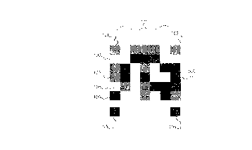
Fig 4 illustrates, at 400, output from a development option of the program. The label in
this example illustration is inverted and was optically distorted by lens aberrations. The
size of individual pixels used in the capture of an image is clearly shown as small
squares - this illustration is but a small portion of an entire captured image.
In this illustration the software has picked out four locators; 402, 403, 404 and 407. It
has ignored other dark masses which failed to satisfy the criteria for a locator, which
criteria include a certain range of permitted sizes, and a contrasting zone 40~
surrounding each locator. Dark masses which were ignored include the data matrix401, the bar-code array 410, and other dark material 409 in the image. The software has
verified that the locators belong together, after centroid location of their centres, by
constructing a rather crude rectangle (lines and diagonals shown as 408). The software
has then identifled a matrix of 7 x 6 points, and marked them by crosses 406 overlying
the expected centres of cells carrying data. On the computer's display screen, these
crosses are in red, green, or blue corresponding to the ternary values (0,1 or 2) detected
by reading the value of the underlying pixel. Not shown is the process for allocating a
CA 0221~026 1997-09-10
WO 96/30217 PCI~/~Z96/Q0021
.
- 19-
point on a grey scale to each cell, (which might be shown as a frequency histogram) or
compensation for uneven lighting
S TRIALS
The entire system has not been field-tested at the time of filing this application. A
worst-case trial was arranged to check the error rate, which should be no more than 1 in
100,000. A photographer went to a wharf and took photographs of about 105 defaced
10 bar-coded labels which had suffered some form of field damage, from a selectiop of
about 70,000 labelled logs. We made up a transparent grid with a matrix ruled on it to
find out how many cells (had they been printed onto the labels) would have been
rendered badly decoded. We assumed use of the preferred BCH code, in which 47
bina~y bits fitted into 30 ternary bits are placed in a cell array on the label.
If an error in co~ ulel reading exists, we estim~te a cell error arrival rate of 0.09% for
the present size of cells. We estimate the overall average probability of misreporting
of data cells after correction to be about 1 in 200,000. As 3-bit error correction tends to
raise the overall risk of miscorrection. We prefer to reject a label outright if more than
20 2, or preferably if more than l bit requires correction. This study resulted in a final
misreporting error rate (where there was an initial machine-reading error) of about 1 in
200,000, and 99.76% of labels would be read correctly.
VARIATIONS
Most variations have been discussed in the text as the occasion arises, while we may
also mention the possibility of using non-rectangular cell markings or indicia: such as
more prominent locators, which may be circular or elliptical or of any other shape
(perhaps a company logo may be one of these).
30 Reflective locators may be used for higher contrast. Labels printed on a retro-reflective
surface (that is, one which returns light substantially back towards its source) may be
used, and in that case the intensity of the flash may be lessened which at least assists the
person carrying its battery pack.
35 We would like to again state that a ternary base for the cell information is preferred for
this particular application, and binary, or higher bases may be used in other
CA 02215026 1997-09-10
WO 96/30217 PCI~/NZ96/00021
.
- 20 -
applications.
ADVANTAGES
s
The advantages of the pief~llt;d forms of this invention are:
(1) While maintaining a small area, the symbol or label can be detected, and read
accurately in most circnmct~nres
(2) This applies even after deterioration in the field and image capture in an outdoors
10 environment.
Finally, it will be appreciated that various alterations and modifications may be made to
the foregoing without departing from the scope of this invention as set forth.