Note : Les descriptions sont présentées dans la langue officielle dans laquelle elles ont été soumises.
CA 02215065 1997-09-10
WO 96/28572 PCT/I1S96/02952
- 1 -
APPARAT~tJS AND PROCESS FOR TRANSPORTING MOLTEN METAL
Field of the Invention
The present invention relates to an
apparatus and a process for transporting molten metal.
More specifically, the present invention relates to a
process in which molten metal is transported in a
single transfer vessel from a blast furnace to a basic
oxygen furnace. The present invention also relates to
a transfer vessel that is constructed to facilitate
such process.
Baokc~round of the Invention
In the steel making industry, it is common
to smelt iron ore in a blast furnace to produce hot,
molten pig iron. The molten pig iron is then
transferred to other areas of the steel mill, such as
a basic oxygen furnace, for further processing into
steel. In a steel mill, the molten pig iron is
transferred by means of transfer vessels such as
torpedo or bottle cars.
A torpedo car typically includes an
elongated vessel which is rotatable about its
longitudinal axis, as disclosed for example in U.S.
Patent No. 3,661,374. An opening is formed in the
central portion of the rotatable vessel. Molten metal
is poured into the vessel through the opening when the
vessel is oriented with the opening in an upward-
facing position. The moltei-i metal is discharged from
the vessel through the opening when the vessel is
rotated about its longitudinal axis. Rotation of the
vessel is typically accomplished by a complicated
mechanism which requires frequent maintenance.
CA 02215065 1997-09-10
WO 96/28572 PCTlUS96/02952
- 2 -
In a torpedo car, the vessel is mounted
between spaced apart railcar trucks thereby allowing
the vessel to be transported along rails or tracks. .
Since the rails usually do not run directly between
the blast furnace and the basic oxygen furnace
(hereinafter, b.o.f.), the torpedo car must be
switched from one set of rails to another. Such
shunting increases the time needed to transport the
molten metal to the b.o.f. The tracks and the
locomotive used to pull the torpedo cars must be
frequently maintained.
Typically, the tap hole of a blast furnace
is located on or near the bottom of the furnace and a
torpedo car must therefore be designed to fit beneath
the furnace. Further, large torpedo cars are
difficult to rotate and are less stable due to their
high center of gravity. Hence, the maximum size of
the torpedo cars is limited and many torpedo cars are
generally needed to transfer enough molten metal from
the furnace toconstitute a single charge for the
b.o.f.
The known process of transporting molten
metal from a blast furnace to a b.o.f. is illustrated
schematically in Fig. 7. A transport vehicle
transports a full transfer vessel 78, such as a
torpedo car, from a first discharging location 71 of a
blast furnace 70 to a holding station 80 along a
Path 51. The transport vehicle proceeds along a
Path 52, picks up an empty transfer vessel 78' and
transports it along a Path 53 to the first discharging
location 71. The transport vehicle then proceeds
along a Path 54, picks up the full vessel 78 and
transports it along a Path 55 to a molten metal
pouring station 82, where the contents of the transfer
vessel 78 are cast into a receiving vessel 83. The
first transport vehicle then transports the empty
CA 02215065 1997-09-10
WO 96128572 PCT/IJS96/02952
- 3 -
transfer vessel 78 along Path 56 and positions the
empty transfer vessel 78 at a second discharging
location 71' of the blast furnace 70.
An overhead crane transfers the full
receiving vessel 83 from the pouring station 82 to a
receiving station 85 of the b.o.f. 87 along a Path 57.
The molten metal is typically desulphurized in the
receiving vessel 83 at the receiving station 85. The
overhead crane proceeds along a Path 58 to an empty
receiving vessel 83' which it picks up and transports
along Path 59 to the pouring station 82. A
disadvantage of this process, aside from its
complexity, is the need to build and maintain a
pouring station 82. In addition, the transfer of
molten metal to a receiving vessel 83 typically
results in a 56C (100F) loss of heat. This heat
must later be restored to the molten metal which adds
to the production cost. Further, the transfer of
molten metal to the receiving vessel 83 results in the
release of polluting gases and iron dust into the
environment.
Accordingly, it would be highly advantageous
to provide an apparatus and a process whereby
sufficient molten metal for further processing is
transferred from a furnace directly to a single, large
capacity vessel. This eliminates the need for
transferring the molten metal to a receiving vessel
which, in turn, reduces environmental pollution,
increases the molten metal charge temperature, and
eliminates the cost of building and maintaining a
molten metal pouring station. Preferably, the vessel
should be simple to construct and easy to operate and
maintain. Further, the apparatus should be suitable
for use with existing blast furnaces without requiring
major structural changes to the furnace.
Additionally, the apparatus should be easily adapted
CA 02215065 2000-10-30
WO 96/28572 PCT/US96/02952
- 4 -
for transport by rubber tire or pallet carriers in
order to decrease the transport time and eliminate the
need for locomotives and tracks to transport the
vessel.
Summary of the Invention
The problems associated with the known
transfer vessels and their use, are addressed
by an apparatus and a process in accordance
with the present invention. A quantity of molten
metal for further processing is transferred directly
to a single, large capacity transfer vessel. The
transfer vessel according to the present invention has
sufficient capacity to hold a full charge of molten
metal. This eliminates the need for first discharging
the molten metal to a series of transport vessels and
then later transferring the molten metal to a large
capacity receiving vessel. Elimination of this
transfer step results in a reduction in environmental
pollution, a reduction in the heat lost by the molten
metal charge, and eliminates the need for a molten
metal pouring station.
The apparatus provided by the present invention
comprises a vessel having a first portion with a generally
cylindrical wall, a closed end and an open end. The first
portion has an opening formed in the cylindrical wall for
receiving molten metal therethrough and the open end has an
opening that is commensurate with the inside diameter of the
cylindrical wall. A spout is formed over the open end of
the first portion and has an inlet that is commensurate with
the opening formed in the open end of the first portion.
The spout also has a bottom portion that angeles upwardly to
provide a smooth path along which the molten metal can be
discharged and an orifice through which the molten metal can
be discharged from the vessel. The orifice is disposed so as
to be above a load of molten metal in the vessel when the
vessel is in an untitled position. Means is provided for
fac~~litating discharge of the molten metal from the vessel.
CA 02215065 2000-10-30
WO 96128$72 PCT/US96/02951
- 5 -
In another embodiment, a stand is provided fo~~
supporting the vessel. The support stand is
constructed and arranged to facilitate lifting and
transporting of the vessel by a truck, such as a
pallet carrier truck or a c-frame carrier truck. The
support stand is generally constructed as a free-
standing support having a frame to support the vessel,
a base to support the frame above the ground, and a
stabilizing means to stabilize the vessel when it is
supported by the support stand.
In accordance with an other aspect of the present
invention there is provided a process in which a vessel of
the form defined above is positioned adjacent to a bottom-
tapped processing station containing molten metal. The
molten metal is cast from the bottom-tapped processing
station into the transfer vessel through an opening in its
top. The transfer vessel is transported to a top-loading
processing station and the molten metal is discharged
through a second opening in the top of the transfer vessel
into the top-loading processing station for further
processing.
Brief Description of the Drawings
The foregoing summary, as well as the
following detailed description of a preferred
embodiment of the present invention, will be better
understood when read in conjunction with the
accompanying drawings, of which:
Fig. 1 is a top, front perspective view
showing an apparatus for transporting molten metal in
accordance with the present invention;
Fig. 2 is a side elevation view, in section,
of the apparatus depicted in Fig. 1;
Fig. 3 is a top plan view of the apparatus
depicted in Fig. 1;
CA 02215065 1997-09-10
WO 96/28572 PCTIUS96/02952
- 6 -
Fig. 4 is a front elevation view of the
apparatus depicted in Fig. 1;
Fig. 5 is a side elevation view, in section, .
of an apparatus for transporting molten metal having a
slag skimmer in accordance with the present invention;
Fig. 6 is a partial sectional view of the
spout of the apparatus depicted in Fig. 5 as viewed
along line 6-6;
Fig. 7 is a schematic representation of a
prior art process for transporting molten metal; and
Fig. 8 is a schematic representation of a
process for transporting molten metal in accordance
with the present invention.
Detailed Descrit~tion of the Preferred Embodiments
Referring now to the drawings, and in
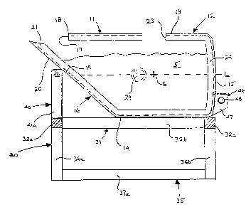
particular to Fig. 1, there is shown an apparatus 10
for transporting molten metal in accordance with the
present invention. Apparatus l0 comprises a vessel 11
which is designed to hold the molten metal.
Preferably, the apparatus 10 also comprises a support
stand 30, designed to support and to facilitate
transport of the vessel 11.
The_vessel 11, as best shown in Figs. 2-4,
comprises a first portion 12 having a generally
cylindrical wall 13, a closed end 15, and an open
end 14. The cylindrical shape provides an even
distribution of the weight of the molten metal 5
thereby increasing the carrying capacity of the
vessel 11. As shown in the~figures, the vessel 11 has
a longitudinal axis L that is preferably oriented
F
horizontally when the vessel 11 is transporting molten
metal 5. An opening 23 is provided in the top of the
cylindrical wall 13. The opening 23 is generally
upwardly facing so that molten metal 5 can be poured
therethrough into the vessel 11. A spout 16 is formed
CA 02215065 1997-09-10
WO 96!28572 PCT/US96/02952
_ 7 _
over the open end 14 of the first portion 12 for
discharging the molten metal 5 out of the vessel 11.
. The spout 16 has an orifice 17, defined by an upper
lip 18 and a lower lip 19 of the spout 16. The
spout 16, the closed end 15, and the cylindrical
wall 13 define an enclosure for holding the molten
metal 5 during transport.
In the embodiment shown in Figs. 2-4, the
spout 16 is formed as an extension of the cylindrical
wall 13. The bottom portion of spout 16 angles
upwardly and tapers down such that the orifice 17,
defined by the upper lip 18 and lower lip 19 of the
spout 16, is substantially smaller in diameter than
the open end 14 of the first portion 12. The slope of
the angled bottom portion of spout 16 is chosen by
considering that the shallower the slope the longer
the overall length of the vessel 11 and the steeper
the slope the more the vessel 11 will need to be
tilted in order to pour the molten metal 5. A semi-
circular trough 20 extends from the spout 16 at the
lower lip 19 of the orifice 17. The trough 20
facilitates pouring of molten metal 5 from the
vessel 11. This arrangement of spout 16 provides a
smooth, angled path along which the molten metal 5 can
be poured. It will also be appreciated, that this
arrangement provides for a spout 16 with a generally
circular cross-section that is perpendicular to the
longitudinal axis L of the vessel 11, thereby more
evenly distributing the weight of the molten metal and
increasing the pouring capacity of the spout 16. As
shown in the figures, the discharge end 21 of the
trough 20 is preferably near the top of the first
portion 12, in order to maximize the holding capacity
of the vessel 11.
CA 02215065 2000-10-30
s WO 96/28572 PCTNS96/02952
- g _
The size and shape of opening 23 are
selected to facilitate the tapping or pouring of
molten metal 5 into the vessel 11. Preferably, the
opening 23 is generally circular or oval, as shown in
Fig. 3. In order to minimize the amount of heat lost
from the molten metal 5 through the opening 23 prior
to and during transport, an insulated lid (not shown)
is provided for closing the opening 23 once the molten
metal 5 has been tapped or poured into the vessel 11.
A suitable lid is disclosed and shown in U.S. Patent
No. 4,524,954.
The cylindrical wall 13, closed end 15, and
spout 16 are preferably made from about 7 cm
(2.8 inch) thick steel. Preferably, the interior
surfaces of the cylindrical wall 13, closed end 15,
and spout 16 are lined with an insulating material
lining 24 to protect the vessel 11 from the extreme
temperatures of the molten metal (in excess of 1480°C
(2700°F)), to retain heat, and to limit erosion of the
metal walls. For example, the vessel 11 can be lined
with a 23 cm (9 inch) thick layer of a standard,
commercially available, high alumina lining. Since
the region of the vessel 11 opposite the opening 23 is
most prone to thermal stress and erosion, the
lining 24 in that area is preferably thicker than the
rest of the lining 24.
In a further embodiment of the apparatus
according to the present invention, vessel 11 includes
a skimmer for skimming slag 6 off the top of the
molten metal 5 as the metal 5 is poured from the
vessel 11. As shown in Figs. 5 and 6, the skimmer
comprises a dam 25 and a partition 27. The
partition 27 extends from the upper lip 18 of the
spout 16 and projects into the vessel 11, so that the
free end 28 of partition 27 is below the level of the
CA 02215065 1997-09-10
WO 96!28572 PCT/US96l02952
_ g _
slag 6 which floats on top of the molten metal 5.
Preferably, the free end 28 of the partition 27 is cut
or machined at an angle parallel to the slope of the
spout 16. The partition 27 is preferably manufactured
from the same material as the cylindrical wall 13.
The dam 25 comprises a raised ridge 26 on the
discharge end 21 of the trough 20. The dam 25 helps
to maintain the upper level of the molten metal 5
above the free end 28 of the partition 27 as the
molten metal is poured out of the vessel. Preferably,
the height of the ridge 26 is about the same as the
distance from the free end 28 of the partition 27 to
the spout 16.
To facilitate pouring of the molten metal 5
from the vessel 11, trunnions 29 are attached to the
exterior of vessel 11 on the cylindrical wall 13. As
shown in Fig. 3, the trunnions 29 are perpendicular to
the longitudinal axis L of the vessel il and equally
spaced on either side of the opening 23, so that an
axis passing through the centers of the trunnions 29
lies in a horizontal plane, the horizontal plane
intersecting with the center of gravity G of the
vessel 11 when filled with molten metal 5. The axis
running through the center of the trunnions 29 is
located between the spout 16 and the center of
gravity G of the vessel 11 when filled with molten
metal 5. Such an arrangement inhibits accidental
tipping of the vessel 11. A tilting lug 46 is
attached to the closed end 15 of the first portion 12
of vessel 11. Preferably, the tilting lug 46
comprises two plates 47 in spaced parallel relation
which are welded to the bottom, center of the closed
end 15. A pin 48 extends between and through the
plates 47 and is generally perpendicular thereto. An
overhead crane can be used to lift the vessel 11 by
the trunnions 29. When thus supported, the vessel 11
CA 02215065 1997-09-10
WO 96/28572 PCTlUS96/02952
- 10 -
can be tilted by using a holding block of the crane to
pull upwardly on the tilting lug 46, thereby
discharging the molten metal 5 into a steel making
furnace, for example.
The dimensions of the vessel 11 are chosen
based on the manner in which the vessel 11 will be
used. For example, if the vessel 11 is to be used for
transporting molten metal from a blast furnace to a
b.o.f., the vessel 11 must be designed to fit within
the space adjacent to the discharging location of the
blast furnace, preferably without major structural
modification of the blast furnace. Additionally,
vessel 11 is designed to carry a quantity of molten
metal approximately equal to, or greater than, the
charge size of the b.o.f., or other metal processing
device. In order to match the dimensions of the
vessel 11 to the needs of specific applications, the
length and the diameter of the cylindrical first
portion 12 of the vessel 11 can be varied in
accordance with known methods.
Referring again to Fig. 1, the apparatus 10
includes a support stand 30. The support stand 30 is
generally constructed from structural steel to be a
free-standing support for the vessel 11. The support
stand 30 is also constructed to facilitate
transporting the vessel 11 by providing an arrangement
by which a pallet carrier or rubber tire carrier can
carry the vessel 11. The precise shape and dimensions
of the support stand 30 depends upon the size of the
vessel 11. Since the molten metal 5 is generally
discharged through a tap hole at the bottom of the
furnace, the vessel 11 together with the support
stand 30 must be dimensioned so that both the
vessel 11 and the stand 30 fit beneath the furnace
without major structural modification to the furnace.
CA 02215065 1997-09-10
WO 96/28572 PCT/U596/02952
- 11 -
The support stand 30 generally comprises a
frame 31 to support the vessel 11, a base 35, and a
stabilizer 40. The base 35 supports the frame 31
above the ground. The stabilizer 40 extends from
frame 31 to prevent the vessel 11 from rotating or
shifting when the vessel 11 is supported on stand 30.
The stabilizer 40 preferably comprises a yoke or
struts which support the spout 16 of the vessel 11. A
second stabilizer (not shown) can be used to support
the cylindrical wall 13 for better stability.
In a preferred embodiment as shown in
Figs. 1,2, and 4, the frame 31 of the support stand 30
is constructed of four beams 32a-d arranged in a
rectangular fashion. The length of the rectangle is
longer than the length of the first portion 12 of the
vessel 11 but shorter than the overall length of the
vessel 11. Thus, the vessel 11 can be positioned with
the bottom portion of the cylindrical wall 13 resting
lengthwise on the frame 31. The base 35 comprises
struts 36a-d each extending downwardly from one of the
four corners of the frame 31. A first beam 37a
interconnects the struts 36a and 36b on one side of
the stand 30 to each other. A second beam 37b (not
shown) interconnects the other two struts 36c and 36d
of stand 30. The base 35 supports the frame 31 above
the ground, so that the lift mechanism of a pallet
carrier can be easily positioned under frame 31. The
stabilizer 40 comprises two struts 41a and 41b
extending upwardly from the front of the frame 31.
Struts 41a and 41b are positioned so that the free
ends 42a and 42b thereof bear against spout 16. The
lengths of the struts 41 are chosen so that the
longitudinal axis L of the vessel 11 is parallel to
the frame 31 when the vessel 11 is supported by the
support stand 30.
CA 02215065 1997-09-10
WO 96/28572 PCT/US96/02952
- 12 -
The process according to the present
invention is illustrated schematically in Fig. 8. An
apparatus 10 or vessel 11, as described hereinabove,
is positioned at a charging location 71 of a first
processing station 70 containing molten metal, such as
a blast furnace. The molten metal 5 is allowed to
flow from the first processing station 70 into the
vessel 11 until it is substantially filled with molten
metal 5. The vessel 11 is then transported to a
receiving station 85 of a second processing
station 87, such as a b.o.f. The molten metal 5 is
discharged from the vessel 11 to the second processing
station 87 without the need for first transferring the
molten metal 5 to a second receiving vessel as is done
in the known practice.
Preferably, the vessel 11 is positioned at
the charging location 71 of the first processing
station 70 and/or transported to the second processing
station 87 using a truck, such as a pallet carrier
truck (Kress Model EP-660C) or a c-frame carrier truck
(Kress Model LE-600C). In an embodiment where the
apparatus 10 includes a support stand 3o such as the
one shown in Figs. 1, 2, and 4, the stand 30 acts as a
pallet which can be lifted by the pallet carrier truck
to facilitate transport of the vessel 11 to the second
processing station 87 where further processing is to
take place. The vessel 11 is first positioned on the
support stand 30 by, for example, an overhead crane.
The pallet carrier truck is then positioned with the
lifting mechanism of the truck under the frame 31 of
the support stand 30. When operated, the lifting _
mechanism exerts an upward force on the frame 31
thereby lifting the support stand 30 and the
vessel 11. The use of a pallet carrier truck or a c-
frame carrier truck eliminates the need for rails or
tracks running between the first processing station 70
CA 02215065 1997-09-10
WO 96/28572 PCT/US96/02952
- 13 -
and the second processing station 87 and shortens the
transportation time.
More specifically, in the process according
to the present invention, molten metal 5 is discharged
through a tap hole of the blast furnace 70 to a first
discharging location 71 using, for example, a
runner 73. The molten metal 5 flows into a first
vessel 11 which has been positioned at the first
discharging location 71 of the furnace 70. When the
first vessel 11 is substantially full, the flow of
molten metal is diverted to a second vessel 11'
located at the second discharging location 71'. The
full first vessel 11 is transported by a transport
vehicle along Path 61 from the charging location 71 of
the blast furnace 70 to a holding station 80. The
transport vehicle proceeds along Path 62, picks up an
empty third vessel 11" , and transports it-along
Path 63 to the first charging location 71. The
transport vehicle then proceeds along Path 64 to
holding station 80, picks up the first vessel 11, and
transports it along Path 65 directly to the receiving
station 85 of the b.o.f. 87, without transferring the
molten metal 5 to a separate receiving vessel 83. The
transport vehicle then proceeds along Path 66, picks
up an empty fourth vessel 11 " ', and transports it
along Path 67 to the holding station 80 so that it can
be used to replace the second vessel 11' once the
second vessel 11' has been filled. This process is
repeated until the entire charge from the blast
furnace 70 has been transported to the b.o.f. 87.
. In the preferred embodiment, two transport
vehicles are used. The full first vessel 11 is
transported by the first transport vehicle along
Path 61 from the charging location 71 of the blast
furnace 70 to a holding station 80. The first
transport vehicle proceeds along Path 62, picks up an
CA 02215065 2000-10-30
WO 96/18572 PC'T/US96/01952
- 14 -
empty vessel 11 ", and transports it along Path 63 to
the first charging location 71. The first transport
vehicle is then ready to repeat the process for a
second vessel 11'. The second transport vehicle picks
up the first vessel 11 at the holding station 80 and
transports it,along Path 65 directly to the receiving
station 85 of the b.o.f. 87, without transferring the
molten metal 5 to a separate receiving vessel 83. The
second transport vehicle then proceeds along Path 66,
picks up an empty fourth vessel 11 " ', and transports
it along Path 67 to the holding station 80 so that it
can be used to replace the second vessel 11' once the
second vessel 11' has been filled.
A desulphurization step can be performed on
the molten metal 5 between the blast furnace 70 and
the b.o.f. 87. When desulphurization is necessary, it
can be performed directly in the vessel 11 by, for
example, inserting an oxygen lance into the molten
metal 5 through the opening 23 of the vessel 11. A
lance suitable for this purpose is described in U.S. Patent
No. 4,848,751. Preferably, desulphurization,is performed
at the receiving station 85 of the b.o.f. 87. In this
respect, the process and apparatus according to the
present invention obviate the need for a separate
pouring station.
It will be recognized by those skilled in
the art that changes or modifications may be made to
the above-described embodiments without departing from
the broad inventive concepts of the invention. It
should therefore be understood that this invention is
not limited to the particular embodiments described
herein, but is intended to include all changes and
modifications that are within the scope and spirit of
the invention as set forth in the claims.