Sélection de la langue

Search

Sommaire du brevet 2215295 

Énoncé de désistement de responsabilité concernant l'information provenant de tiers

Une partie des informations de ce site Web a été fournie par des sources externes. Le gouvernement du Canada n'assume aucune responsabilité concernant la précision, l'actualité ou la fiabilité des informations fournies par les sources externes. Les utilisateurs qui désirent employer cette information devraient consulter directement la source des informations. Le contenu fourni par les sources externes n'est pas assujetti aux exigences sur les langues officielles, la protection des renseignements personnels et l'accessibilité.

Disponibilité de l'Abrégé et des Revendications

L'apparition de différences dans le texte et l'image des Revendications et de l'Abrégé dépend du moment auquel le document est publié. Les textes des Revendications et de l'Abrégé sont affichés :

  • lorsque la demande peut être examinée par le public;
  • lorsque le brevet est émis (délivrance).
(12) Brevet: (11) CA 2215295
(54) Titre français: SABOT DE PROJECTILE SOUS-CALIBRE
(54) Titre anglais: SABOT FOR A SUBCALIBER PROJECTILE
Statut: Périmé et au-delà du délai pour l’annulation
Données bibliographiques
(51) Classification internationale des brevets (CIB):
  • F42B 14/06 (2006.01)
(72) Inventeurs :
  • ROSSMANN, RUDOLF (Suisse)
(73) Titulaires :
  • OERLIKON-CONTRAVES PYROTEC AG
(71) Demandeurs :
  • OERLIKON-CONTRAVES PYROTEC AG (Suisse)
(74) Agent: MACRAE & CO.
(74) Co-agent:
(45) Délivré: 2000-08-22
(22) Date de dépôt: 1997-09-11
(41) Mise à la disponibilité du public: 1998-07-27
Requête d'examen: 1997-09-11
Licence disponible: S.O.
Cédé au domaine public: S.O.
(25) Langue des documents déposés: Anglais

Traité de coopération en matière de brevets (PCT): Non

(30) Données de priorité de la demande:
Numéro de la demande Pays / territoire Date
1997 0167/97 (Suisse) 1997-01-27

Abrégés

Abrégé français

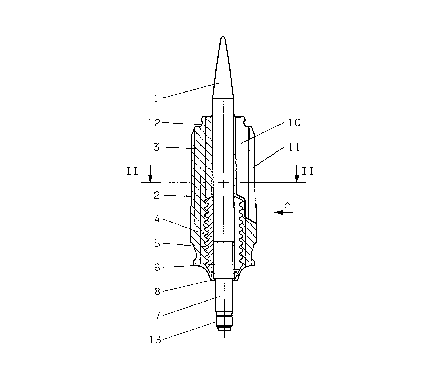
Sabot permettant d'obtenir un joint optimal de retenue du gaz et de diminuer le poids et le risque que présente la formation d'éclats de métal. A cette fin, le corps du sabot (4) est totalement entouré d'une douille de sabot (3) qui recouvre en partie l'arrière du projectile (1). Le corps du sabot (4) a la forme d'un corps creux constitué d'une ou de plusieurs pièces; il est muni de rainures sur sa circonférence (5, 34) et a un diamètre extérieur qui est inférieur à celui de la douille du sabot. (Fig. 1)


Abrégé anglais


This sabot results in an optimal gas seal and reduction
in the weight and the risk posed by the formation of metal
splinters. For this purpose, the sabot body (4) is completely
enclosed by the sabot casing (3) which partly also encloses
the rear of the pointed projectile (1). The sabot body (4)
has the shape of a one-part or multiple-part hollow body with
circumferential grooves (5, 34), and an exterior diameter
which is smaller than the diameter of the sabot casing.
(Fig. 1)

Revendications

Note : Les revendications sont présentées dans la langue officielle dans laquelle elles ont été soumises.


THE EMBODIMENTS OF THE INVENTION IN WHICH AN EXCLUSIVE
PROPERTY OR PRIVILEGE IS CLAIMED ARE DEFINED AS FOLLOWS:
1. A sabot for a pointed subcaliber projectile
having a sabot body (4) inside which the pointed projectile
(1) is anchored, and a sabot casing (3) encompassing at least
a portion of the front of the pointed projectile (1) and a
portion of the sabot body (4), characterized in that
the sabot body (4) is completely encompassed by the
sabot casing (3) which also encompasses a portion of
the rear of the pointed projectile (1), and that the
sabot body (4) takes the form of a one-part or
multi-part hollow body with circumferential grooves
(5, 34) and has an exterior diameter which is
smaller than the diameter of the sabot casing (3).
2. A sabot according to Claim 1 characterized in
that the sabot casing (3) has channels (10) and slits (11).
3. A sabot according to Claim 1, whereby the sabot
casing (3) is divided into segments, characterized in that
a plurality of channels (10) with an essentially
prismatic cross-section are equally spaced around
the circumference on the front part of the sabot
casing (3), conically narrowing towards the rear,
and that the channels (10) are connected to the
surface of the sabot casing (3) via slits (11) which
also conically narrow towards the rear, thus forming
the segments.
-7-

4. A sabot according to Claim 3 characterized in that
the sabot casing (3) has three, four or six channels (10)
and slits (11).
5. A sabot according to Claim 1, whereby the sabot body
(4) is divided into segments, characterized in that
the sabot body (4) has a plurality of slits (21) forming
the segments, spaced equally around the circumference and
extending from the front (22) to the rear of the sabot
body (4).
6. A sabot according to Claim 5, characterized in that
the slits (21) are delimited by rated break points (23)
at the front of the sabot body (4).
7. A sabot according to Claim 5, characterized in that
the slits (21) are delimited by rated break points (23)
at the rear of the sabot body (4).
8. A sabot according to Claim 5, characterized in that
the slits (21) are delimited by rated break points (23)
at both ends of the sabot body (4).
9. A sabot according to Claim 6 or 7, characterized in
that
the delimiting surfaces (24) of the rated break points
(23) are located on an arc of a circle (25) with center
-8-

of curvature (26) located on the center axis (27) of the
sabot body (4).
10. A sabot according to Claim 5 characterized in that
the sabot body (4) has six slits (21) offset by an angle
of 60 °.
11. A sabot according to Claim 5 characterized in that
the sabot body (4) has four slits (30) offset by an angle
of 90°.
12. A sabot according to Claims 10 or 11, characterized
in that
recesses (31) which extend along the entire length of the
sabot body (4) are provided in the area of the slits (30)
with the center (32) of the curvatures located on an axis
of symmetry (33) of the slits (30).
13. A sabot according to Claim 12, characterized in that
circumferential grooves (34) are formed exclusively in
the area of the recesses (31) extending along the entire
length of the sabot body (4).
14. A sabot according to Claim 1, characterized in that
the sabot body (4) comprises a multi-part catch part in
segment form anchored to the pointed projectile (1),
whereby the individual segments are connected to one
another via separating surfaces (28) and whereby the
-9-

segments have a plurality of circumferential grooves (5)
equally spaced around the circumference.
-10-

Description

Note : Les descriptions sont présentées dans la langue officielle dans laquelle elles ont été soumises.

CA 0221~29~ 1997-09-11
Sabot for a Subcaliber Pro;ectile
The invention relates to an ejectable sabot for a pointed
subcaliber projectile, having a sabot body in which the
pointed projectile is anchored, and a sabot casing
encompassing at least a portion of the front end of the
pointed projectile and a portion of the sabot body.
In a sabot of this type, both the sabot body and the
sabot casing are segmented, which may result in leaks at the
contact surfaces of the sabot segments on one hand, and of the
pointed projectile and the segments of the sabot body on the
other hand.
From EP-A- 0 624 774, a sabot according to the preamble
is known, in which a special segmentation of the sabot body in
the form of longitudinal slits, having at least in part a T-
shaped cross-section, is used to eliminate the above-mentioned
sealing problems. Furthermore, a gas-tight seal is created by
a sealing cap with terminal seal, and rated break points are
provided in the area of the inside diameter of the sabot.
This sabot has a relatively complicated design and is
therefore rather expensive to manufacture. Also, gas leaks may
occur at the location of the joints between the sabot casing
and the sabot body. Furthermore, because of the size of the
sabot body, the e~ection of the sabot during discharge results
in relatively large metal splinters.

CA 0221~29~ 1997-09-11
The present invention is aimed at designing a sabot of
the above type without the above- mentioned drawbacks.
This aim is met with the invention described in Claim 1.
In the design according to the invention, the sabot is fully
enclosed by the sabot casing which also partially encloses the
rear of the pointed projectile. The sabot body has the shape
of a hollow cylinder with circumferential grooves, and a
diameter which is smaller than that of the sabot casing.
Particularly advantageous designs of the sabot are
described in the sub-claims.
The sabot according to the invention has the advantage
that the complete embedding of the sabot body in a sabot
casing made of a synthetic material, produces an optimum seal
due to the absence of any metallic surfaces and the prevention
of micro-fissures. The sabot body is easy to manufacture and
small in comparison to the prior art, resulting in a reduced
overall weight of the sabot and smaller and lighter-weight
metal splinters produced during the discharge, thus
diminishing the danger zone in the vicinity of the muzzle.
The rated break points of the sabot are designed so that an
easy separation takes place after the discharge. The pointed
projectile has only a few catch grooves, resulting in an
optimized air resistance profile and relatively low weight
reduction. The invention is described in detail below, based

CA 0221~29~ 1997-09-11
on two embodiments presented on the accompanying drawing, in
which:
Fig. 1 is a longitudinal section along the line I-I in
Fig. 2 through a sabot with pointed projectile
according to the invention,
Fig. 2 is a cross-section through the sabot along the
line II-II in Fig. 1,
Fig. 3 is a view of the sabot in the direction of the
arrow A in Fig. 1,
Fig. 4 is a view of the sabot in the direction of the
arrow B in Fig. 3,
Fig. 5 is a longitudinal section along the line IV-IV
in Fig. 6, through a variation of the sahot
with pointed projectile according to the
invention.
Fig. 6 is a cross-section through the sabot along the
line III-III in Fig. 5,
Fig. 7 is an enlarged longitudinal section through a
sabot body along the line V-V in Fig. 9,
Fig. 8 is an enlarged longitudinal section through a
sabot body along the line VI-VI in Fig. 10,

CA 0221~29~ 1997-09-11
Fig. 9 is a view of the sabot body in its first
embodiment in the direction of the arrow C in
Fig. 7, and
Fig. 10 is a view of the sabot in its second embodiment
in the direction of the arrow D in Fig. 8.
In Fig. 1 through 4, the reference number 1 denotes a
pointed projectile and the reference number 2 denotes a sabot
on the pointed projectile 1. The sabot 2 consists of a sabot
casing 3 made of a high-temperature, fiber reinforced
thermoplastic synthetic material and a sabot body 4 made of a
light metal. The sabot body 4 is completely enclosed by the
sabot casing 3, with the sabot casing 3 engaging into
circumferential grooves 5 of the sabot body 4 and encompassing
a portion of the front and rear of the pointed projectile 1.
The pointed projectile 1 is secured to the sabot body 4 with a
screw connection, whereby the length of a thread 6 of the
projectile 1 has been kept short to attain better flight
characteristics. The thread 6 protrudes from the sabot body 4
and transitions into a smooth shaft 7 with a smaller diameter,
forming a shoulder 8 which is encompassed by the sabot casing
3. The sabot casing 3 has, at its rear, a plurality of
indentations 9 functioning as rated breakpoints. In the front
portion of the sabot casing 3, six channels 10 with
essentially prismatic cross-sections are equally spaced around
the circumference and conically narrow towards the rear. The
channels 10 are connected, via slits 11 which also conically

CA 0221~29~ 1997-09-11
narrow towards the rear, to the surface of the sabot casing 3,
thus forming six segments. It is also possible, however, to
design the sabot casing 3 with three, four or five channels 10
and slits 11. The reference number 12 marks a groove used to
secure a cap not shown on the drawing. The rear of the
pointed projectile 1 has an additional thread 13 to which a
stabilizing wing may be attached, which is also not shown on
the drawing.
The sabot body 4, as shown in Fig. 5 and 6, is a multi-
part hollow body with an exterior diameter which is smaller
than that of the sabot casing 3, comprising segments with
circumferential grooves 5. The segments are joined via so-
called disconnects 28 and have, at their end sections, an
interior toothing to anchor the hollow body that forms the
sabot body with its pointed projectile 1. An additional
fastening grove 35 is provided in the rear section of the
sabot casing 3.
In a further embodiment of the invention illustrated in
Fig. 7 and 9, the actual sabot body 4 consists of a hollow
cylinder with circumferential grooves 5 and an exterior
diameter which is smaller than the diameter of the sabot
casing 3. The sabot body 4 has, at its rear, an interior
thread 20 for a screw connection of the pointed projectile 1.
Inside the sabot body 4, six slits 21 are equally spaced
around the circumference, forming six segments extending from
the front 22 to the rear of the sabot body 4, where they are

CA 0221~29~ 1997-09-11
delimited by rated break points 23. In further embodiments of
the invention, which are not shown on the drawing for ease of
viewing, the rated break points 23 are located at the front 22
and/or the middle section of the slits 21.
As shown in detail in Fig. 8, the delimiting surfaces 24
of the rated break points 23, for example, are located on the
arc of a circle 25 with center of curvature 26 located on the
center axis 27 of the sabot body 4. In lieu of six slits 21,
the sabot body 4 may also have three, four of five slits 21,
resulting in the formation of the same number of segments.
In the sample embodiment presented in Fig. 8 and 10, the
sabot body 4 has four slits 30 offset by an angle of 90 .
Four circular arc-shaped recesses 31 extend along the entire
length of the sabot body 4 in the area of the slits 30, with
the center of curvature 32 of the circular arcs located on an
axis of symmetry 33 of the slits 30. The recesses 31 alone
have grooves 34 corresponding to the circumferential grooves 5
of the embodiment shown in Fig. 7. Fig. 8 shows a
longitudinal section through the grooves 34 along the line VI-
VI of Fig. 10. This design results in a further significant
reduction in weight, along with a further reduction of the
risk posed by metal splinters produced after the discharge.

Dessin représentatif
Une figure unique qui représente un dessin illustrant l'invention.
États administratifs

2024-08-01 : Dans le cadre de la transition vers les Brevets de nouvelle génération (BNG), la base de données sur les brevets canadiens (BDBC) contient désormais un Historique d'événement plus détaillé, qui reproduit le Journal des événements de notre nouvelle solution interne.

Veuillez noter que les événements débutant par « Inactive : » se réfèrent à des événements qui ne sont plus utilisés dans notre nouvelle solution interne.

Pour une meilleure compréhension de l'état de la demande ou brevet qui figure sur cette page, la rubrique Mise en garde , et les descriptions de Brevet , Historique d'événement , Taxes périodiques et Historique des paiements devraient être consultées.

Historique d'événement

Description Date
Le délai pour l'annulation est expiré 2017-09-11
Lettre envoyée 2016-09-12
Accordé par délivrance 2000-08-22
Inactive : Page couverture publiée 2000-08-21
Inactive : Taxe finale reçue 2000-05-18
Préoctroi 2000-05-18
Un avis d'acceptation est envoyé 2000-04-20
Lettre envoyée 2000-04-20
month 2000-04-20
Un avis d'acceptation est envoyé 2000-04-20
Inactive : Approuvée aux fins d'acceptation (AFA) 2000-04-03
Modification reçue - modification volontaire 2000-01-07
Inactive : Dem. de l'examinateur par.30(2) Règles 1999-08-11
Demande publiée (accessible au public) 1998-07-27
Inactive : CIB attribuée 1998-01-20
Symbole de classement modifié 1998-01-20
Inactive : CIB en 1re position 1998-01-20
Inactive : Certificat de dépôt - RE (Anglais) 1997-11-17
Lettre envoyée 1997-11-17
Demande reçue - nationale ordinaire 1997-11-17
Exigences pour une requête d'examen - jugée conforme 1997-09-11
Toutes les exigences pour l'examen - jugée conforme 1997-09-11

Historique d'abandonnement

Il n'y a pas d'historique d'abandonnement

Taxes périodiques

Le dernier paiement a été reçu le 1999-08-17

Avis : Si le paiement en totalité n'a pas été reçu au plus tard à la date indiquée, une taxe supplémentaire peut être imposée, soit une des taxes suivantes :

  • taxe de rétablissement ;
  • taxe pour paiement en souffrance ; ou
  • taxe additionnelle pour le renversement d'une péremption réputée.

Les taxes sur les brevets sont ajustées au 1er janvier de chaque année. Les montants ci-dessus sont les montants actuels s'ils sont reçus au plus tard le 31 décembre de l'année en cours.
Veuillez vous référer à la page web des taxes sur les brevets de l'OPIC pour voir tous les montants actuels des taxes.

Titulaires au dossier

Les titulaires actuels et antérieures au dossier sont affichés en ordre alphabétique.

Titulaires actuels au dossier
OERLIKON-CONTRAVES PYROTEC AG
Titulaires antérieures au dossier
RUDOLF ROSSMANN
Les propriétaires antérieurs qui ne figurent pas dans la liste des « Propriétaires au dossier » apparaîtront dans d'autres documents au dossier.
Documents

Pour visionner les fichiers sélectionnés, entrer le code reCAPTCHA :


Pour visualiser une image, cliquer sur un lien dans la colonne description du document (Temporairement non-disponible). Pour télécharger l'image (les images), cliquer l'une ou plusieurs cases à cocher dans la première colonne et ensuite cliquer sur le bouton "Télécharger sélection en format PDF (archive Zip)" ou le bouton "Télécharger sélection (en un fichier PDF fusionné)".

Liste des documents de brevet publiés et non publiés sur la BDBC .

Si vous avez des difficultés à accéder au contenu, veuillez communiquer avec le Centre de services à la clientèle au 1-866-997-1936, ou envoyer un courriel au Centre de service à la clientèle de l'OPIC.

({010=Tous les documents, 020=Au moment du dépôt, 030=Au moment de la mise à la disponibilité du public, 040=À la délivrance, 050=Examen, 060=Correspondance reçue, 070=Divers, 080=Correspondance envoyée, 090=Paiement})


Description du
Document 
Date
(aaaa-mm-jj) 
Nombre de pages   Taille de l'image (Ko) 
Abrégé 1997-09-10 1 14
Revendications 1997-09-10 4 88
Description 1997-09-10 6 198
Dessins 1997-09-10 3 53
Revendications 2000-01-06 4 97
Dessin représentatif 1998-07-26 1 7
Dessin représentatif 2000-07-26 1 7
Courtoisie - Certificat d'enregistrement (document(s) connexe(s)) 1997-11-16 1 116
Certificat de dépôt (anglais) 1997-11-16 1 164
Rappel de taxe de maintien due 1999-05-11 1 112
Avis du commissaire - Demande jugée acceptable 2000-04-19 1 164
Avis concernant la taxe de maintien 2016-10-23 1 178
Correspondance 2000-05-17 1 28