Note : Les descriptions sont présentées dans la langue officielle dans laquelle elles ont été soumises.
CA 02215661 1997-09-16
1
MODULAR STRUCTURES
This invention relates to modular structures,
particularly to modular buildings. The invention is
particularly concerned with modular buildings comprising
walls, floor and roof, with the walls being based upon a
foldable frame structure.
In DE-A-2620689 there is described a transportable
building which consists of a three-dimensional central cabin
to which are connected pivotable wall and roof sections. When
these are folded up to the central cabin one has a unit which
resembles a container for transportation.
In GB-A-2172915 there is described a foldable building
structure, such as a shed or lean-to. The structure is
collapsible and is intended to be mounted against a wall.
In the design of modular buildings it is important that
they should be capable of being easily and quickly assembled,
that the structures should be simple in order to aid assembly
and dismantling, and that they should be versatile so that a
variety of different building layouts can be constructed with
as small a number as possible of basic components. It is also
important thatthe components of the structure should be
sealed to prevent the ingress of water.
It is one object of the present invention to provide a
modular structure, especially for use as a building, in which
these objects are achieved and where one basic modular unit
can be used as a key component of a variety of different
structures.
It is another object of the invention to provide a
building module which can be transformed in minutes from a
flat pack to an erected, rigid structure without the need for
APõINDED SNEET
CA 02215661 1997-09-16
-la-
special tools, skilled labour or cranes. The structure can
equally easily be dismantled to a flat pack for
transportation, redeployment or storage.
In accordance with the invention there is provided a
modular unit for a building, comprising a central body and
four walls pivotable relative to the central body and arranged
in pairs on each side of the central body,
characterised in that the central body comprises linear
structural members connected together to define an open-
centred frame, and the walls and frame together give an I-
shaped configuration with at least one pair of the opposing
pairs of walls being foldable towards the frame to make a unit
of [-shaped or ] -shaped
~~'l
CA 02215661 1997-09-16
WO 96/26329 PCTIGB96lDD322
-2-
configuration.
Preferably, both pairs of opposing walls are
foldable towards the central frame so that the unit is
substantially flat for transportation and/or storage.
In a preferred embodiment, the outer vertical
edges of the walls are provided with connector means to
enable wall-to-wall connections to be made with an
adjacent modular unit or units.
The foldable nature of the modules means that
substantial savings can be achieved in terms of
transport and necessary personnel for deployment or
retrieval, as compared with conventional temporary
portable structures.
With conventional portable structures what
you see is what you get. With the modular structures
of the present invention they are easily adaptable to
create additional space as needed. This can be
achieved by the addition of extra modules and movement
of internal partitions.
The modular units of the present invention
can be "fitted out" through the opposing pairs of
foldable walls, i.e. openable end panels. This is
particularly advantageous where large items are
concerned and where one would normally have to
dismantle the item for access through doorways.
It is a further advantage of the invention
that wall panels, for example if damaged, can readily
be replaced and without the need to dismantle the whole
structure.
The modular building units of the present
invention find widespread application. They can be
used inside buildings or outside, for office, light industrial, military and
residential purposes.
Examples include use as waiting rooms, canteens,
dormitories, hospitals, stores, clinics, security posts
CA 02215661 1997-09-16
WO 96126329 PCT/GB96/00321
-3-
and barracks.
Preferably, sealing means are provided
between the component parts of the modular building
structure, for example between frames and panels and
between individual panels.
In order that the invention may be more fully
understood, a number of embodiments of modular
structures in accordance with the invention will now be
described by way of example and with reference to the
accompanying drawings. In the drawings:
Fig. 1 is an isometric schematic diagram of a
single module, fully open;
Fig. 2 is an isometric diagram of the module
of Fig. 1, but with one end closed;
Fig. 3 is an isometric diagram of three of
the modules shown in Figs. 1 and 2, arranged as a room;
Fig. 4 is a front view of the single module
shown in Fig. 1, with roof and on an enlarged scale;
Fig. 5 is a side view of the single module as
shown in Fig. 4;
Fig. 6 is the top plan view of the module as
shown in Fig. 4;
Fig. 7 is the top plan view of the central
frame sub-assembly;
Fig. 8 is the front view of the central frame
sub-assembly;
Fig. 9 is the side view of the central frame
sub-assembly;
Fig. 10 is the detail A in Fig. 7, on an
enlarged scale;
Fig. 11 is the sectional view XI-XI in Figs.
8 and 9, on an enlarged scale;
Fig. 12 is the detail B in Fig. 8, on an
enlarged scale;
Fig. 13 is the detail C in Fig. 8, on an
CA 02215661 1997-09-16
WO 96/26329 PCT/GB96/00321
-4-
enlarged scale;
Fig. 14 is the sectional view takeri along the
lines XIV-XIV in Figs. 5 and 6;
Fig. 15 is the sectional view taken along the =
lines XV-XV in Figs. 4 and 6;
Fig. 16 is the sectional view taken along the =
lines XVI-XVI in Figs. 4 and 6;
Fig. 17 is a detail view, on an enlarged
scale, showing the folding of one wall relative to the
central frame, viewed from above;
Fig. 18 is a sectional view corresponding to
Fig. 17;
Fig. 19 is a part-sectional view, to
illustrate the connection of two panels one to another;
Fig. 20 is a side view of a second embodiment
of central frame sub-assembly;
Fig. 21 is a top plan view of the frame of
Fig. 20;
Fig. 22 is a front view of the frame of Fig.
20;
Fig. 23 is an enlarged view of the detail A
of Fig. 20;
Fig. 24 is an enlarged view of the detail B
of Fig. 22;
Fig. 25 is an enlarged view of the detail C
of Fig. 21;
Fig. 26 is a front view of a wall panel for
use with the frame of Figs. 20 to 25;
Fig. 27 is a top plan view of the wall panel
of Fig. 26;
Fig. 28 is an enlarged view of one end of the
wall panel shown in Fig. 27;
Fig. 29 is a side view of a connector for
joining the frame of Fig. 20 to the wall panel of Fig.
26;
CA 02215661 1997-09-16
WO 96/26329 PCT/GB96/00321
-5-
Fig. 30 is a top plan view of the connector
of Fig. 29; and
Fig. 31 is a front view of the connector of
Figs. 29 and 30.
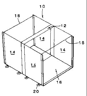
Reference is made first to Figs. 1 to 3 to
illustrate one aspect of the present invention. Fig. 1
shows a single module constructed in accordance with
the present invention and indicated generally at 10.
The module comprises a central, square or rectangular
frame 12, four walls 14, and flooring 16. In practice,
the module would also be provided with a roof, which is
not shown in Figs. 1 to 3 but will be described later.
In Fig. 1 the four walls 14 are shown in an "open"
state, thus providing what is in effect an open-ended
1.5 tunnel. Bracing struts 18 are shown in Fig. 1 to
maintain the position of the walls. The module thus has
an I-shaped configuration in the open state.
Each of the walls 14 is hingedly mounted to
the central frame 12, so as to be pivotable through 90
from the open position as shown in Fig. 1 to a "closed"
position as indicated for two of the walls in Fig. 2.
In Fig. 2, one of the bracing struts 18 has been
removed and two of the walls 14 have been pivoted
through 90 so as to form a closed end to the tunnel.
In the case where two of the walls 14 are "closed", the
module has an ]-shaped or [-shaped configuration. if
all four walls 14 are folded closed, the module is
ready for transportation or storage.
As shown in Fig. 3, one can arrange for
example three modules 10a, lOb, 10c in line to form
what is in effect a room or cabin. The central module
= lOb is in the fully open state, whereas each of the end
modules 10a, lOc has two walls 14 folded into the
closed position in order to provide ends to the room.
The panel-to-panel connections which join the walls and
CA 02215661 1997-09-16
WO 96/26329 PCT/GB96/00321
-6-
the connections between the walls and the central frame
12 will be described hereinafter.
As will be seen in Figs. 1 to 3, each of the
walls is provided with adjustable feet 20. However,
these are optional.
it will be appreciated that by virtue of the =
folding action of the walls 14, the module gives great
versatility in terms of the way in which it can be
linked with other modules to form modular structures of
different sizes and configurations. The key to this is
the fact that each of the four walls 14 which make up a
module is pivotable through 90 between an open
position and a closed position flush with the central
frame 12.
is Reference is now made to Figs. 4 to 6, which
show further details of the modular structure. In
these Figures of the drawings the roof of the structure
is indicated generally at 22. This will be described
in more detail hereinafter. Each pair of adjacent
walls 14 is connected sealingly to the central frame
12. A flap seal 15 runs vertically down the wall, being
anchored to the wall and engaging sealingly against the
central frame 12, or an extension thereof, as shown
more clearly in Fig. 18. Each wall 14 comprises a
panel made from two skins of steel or aluminium, e.g.
0.5mm thick, with a foam polymer core, e.g. 40mm thick.
Each vertical side of each panel 14 has affixed
thereto, as by studs 60 (Fig.18), an aluminium section
58 formed as an extrusion. It is to be noted that the
wall 14 to the left of the central frame 12 has a
handed vertical edge extrusion 58, as compared with the
wall 14 to the right of the central frame which does
not. The flooring 16 is indicated also in Fig. 5.
Reference is now made to Figs. 7 to 13 which
illustrate the construction of the central frame sub-
CA 02215661 1997-09-16
WO 96/26329 PCT/GB96/00321
-7-
assembly 12. The central frame sub-assembly 12
consists of two steel horizontal members 24,' two steel
vertical members 26, each being of tubular
construction, slotted in one of the longer walls, i.e.
the internally facing wall. This is shown most clearly
in Fig. 11 for the vertical member 26. Steel hinge
plates 28 at the top and bottom of the frame are used
to connect the vertical and horizontal members. The
hinge plates 28 are fixedly connected to the central
frame by bolts 25 and the horizontal portion of each L-
shaped hinge plate has a hinge pin 27 welded thereto to
project upwards from the plates at the bottom of the
frame and downwards from the plates at the top of the
frame. As shown most clearly in Fig. 18, the hinge pins
27 seat in holes in the vertical extrusions 58 which
run the height of the walls 14, so that the walls can
be folded relative to the central frame. The sub-
assembly 12 also includes two aluminium seal holders 30
for each vertical frame member 26. These seal holders
30 are connected to the frame members 26 by studs 31
and extend vertically co-extensive with the wall
extrusions 58. Each seal holder 30 carries two lip
seals 32 in the internal faces of the holder, as shown
in Figs. 11 and 18. The lip seals are of silicone
rubber.
Fig. 14 shows the roof structure in more
detail and in particular the way in which two roof
sections are sealed at their junction. In Fig. 14
there is shown a junction between two roof sections 34,
36 above the central frame. Each roof section 34, 36
is of sandwich construction with polyurethane housed
' between two steel skins. A roof seating extrusion of
aluminium is indicated at 38. The roof section 34 has
an aluminium roof edge extrusion 40 along its junction
edge, the extrusion being riveted to the roof section
CA 02215661 1997-09-16
WO 96/26329 PCT/GB96/00321
-8-
34 by rivets 42. The adjoining roof section 36 has a
complementary edge extrusion 40. Between the edge
extrusions 40 there is provided a pair of silicone
rubber compression seals 44 to prevent the ingress of
water between the roof sections. The configuration of
the roof edge extrusions 40 provides a labyrinth-type
seal which provides an effective barrier to the passage
of water.
Fig. 15 shows the construction of the edge of
a roof section 34. The edge of the roof panel is
finished by an edge cover 46 of UPVC material. The
roof seating extrusion 38 is shown below the panel.
This carries a roof-to-wall compression seal 48 at its
underside. The structure is also provided with
guttering 50 on the external surface.
Fig. 16 shows more details of the structure
of the module at the base of one of the walls 14,
showing in particular the method of connecting the
walls 14 to the flooring 16, i.e. by bolting a bracket
51 on the underside of the wall 14 to the underside of
the flooring 16. The flooring may be made of plywood
52 over galvanised steel decking 54.
Figs. 17 and 18 illustrate how the walls 14
are pivotable through 90 relative to the central frame
12. This is accomplished by means of the hinge plates
28, and the hinge pins 27. The edge of each wall 14
adjacent to the central frame 12 is provided with its
wall edge extrusion 58 which is complementary to the
seal holders 30 which are riveted to the central frame
12 by the studs 31. The lip seals 32 which are carried
by the seal holders 30 engage the wall edge extrusions
58'to provide a double vertical seal at each junction
between a wall and the central frame. The sealing is
made more secure by the provision of the flap seal 15 =
which is carried by the wall edge extrusion 58 and
CA 02215661 1997-09-16
WO 96126329 PCT/GB96100321
-9-
overlies the outside face of the seal holder 30 right up
to the junction with the vertical member 26 of the
central frame 12. As can be seen from the right-hand
side of Fig. 18, when the wall 14 is pivoted into its
folded closed position the flap seal 15 still performs
a sealing function, in that it maintains contact with
the rounded end of the seal holder 30 and thereby
maintains the integrity of the outside surface of the
structure. There is thus in all circumstances a total
of three seals 15, 32, 32 between the outside and the
inside of the structure, regardless of whether the
walls 14 are in the open or closed positions. The two
internal lip seals 32 can be seen to maintain their
sealing contact with the wall edge extrusions 58 in all
positions of the walls.
Fig. 19 illustrates the connection between a
pair of adjoining walls 14. The walls are positioned
for interconnection with their vertical edge extrusions
58 in overlapping relationship. Because of the L-
shaped nature of the extrusions 58 the walls 14 are
maintained in alignment. A bolt 66 is used to connect
the overlapping extrusions 58, preferably from the
inside, as shown. Alternatively, an over-centre toggle
clip (not shown) can be used to hold the extrusions 58
together. This is much easier to use than bolts,
without the risk of bolts being lost. Here, the wall
edge extrusion 58 which has two slots, shown as 62 and
64, to carry lip seals, has a lip seal in only one of
the slots, here slot 62, with the other slot 64 being
:30 left empty. This empty slot is the slot which would
carry the flap seal 15 as shown in Fig. 18. With the
provision of a lip seal 32 in slot 62, for each wall
14, one has a double seal between the outside and the
inside of the structure.
Referring now to Figs. 20 to 25 of the
CA 02215661 1997-09-16
WO 96/26329 PCT/GB96/00321
-10-
drawings, there is shown an alternative embodiment of
central frame assembly. The central frame assembly is
here indicated generally at 70. It comprises upper and
lower horizontal members 71 and 72 respectively and two
vertical members 73. In this embodiment, the top of
each of the side members 73 is open. As in the first
embodiment, each of the structural members 71, 72, 73
is hollow with a slot extending the length of each
member and facing towards the interior of the assembly.
At the bottom of each side member 73 there is secured a
base plate 74 by means of a bolt and nut 76. The base
plate 74 projects laterally from the bottom of the
central frame and on each side of the side member 73
carries an upstanding pivot pin 76. The pivot pins 76
are fixedly mounted to the base plates 74.
Figs. 26 to 28 show details of a wall panel
78 adapted to be fitted to the central frame 70 to
provide a structure similar to that shown in the first
embodiment. In this embodiment, each vertical side of
the wall panel 78 is fitted with an elongate extrusion
80. The extrusion 80 is L-shaped in section and has a
vertical hole 82 extending down the length of the
extrusion. This hole 82 is positioned so that it will
receive one of the pivot pins 76 of the base plate 74
when the wall panel 78 is offered up to the central
frame 70 on assembly. As in the first embodiment, the
extrusion 80 is provided with vertically extending
slots 83 to receive lip seals for engagement with a
facing portion of the central frame.
As mentioned above, the top of each side
member 72 of the central frame 70 is open. The
connector indicated generally at 80 in Figs. 29 to 31
is used to link the wall panels 78 to the central frame
70 in a simple way which avoids the need for bolting
parts together as in the first embodiment. The
CA 02215661 1997-09-16
WO 96126329 PCT/GB96/00322
-11-
connector 80 comprises a flat plate 82 which has a U-
shaped portion 84 adjacent to one end. The plate 82
also is provided with a projecting pin 86 which is
welded for example to the plate 82. The pin 86 extends
parallel to the U-shaped portion 84.
In the assembly of a wall panel 78 to the
central frame 70, the wall panel 78 has the hole 82 in
its edge extrusion 80 set down onto the upwardly
projecting pin 76. The wall panel is then held in
alignment with the central frame 70, with the adjacent
edges parallel to one another, and the connector 80 is
then pushed down from above to link the two parts and
bridge the gap between them. The U-shaped portion 84
of the connector fits down into the open upper end of
the side member 73 of the central frame and the
projecting pin 86 of the connector is received in the
hole 82 in the edge extrusion 80 of the wall panel. By
this simple push fit, which may be signified by a
"click", the central frame and the wall panel are
sufficiently connected one to the other for the rest of
the assembly to continue. Because of the absence of any
bolts or other relatively complex connecting means
between the two parts, not only is assembly made easier
but it is also readily possible to remove a wall panel
for replacement if it should become damaged for
example. To remove a wall panel it is simply necessary
to pull out the connector 80 and to lift the panel from
the seating pins 76 at the base.
In each of the embodiments, because the
structural members which make up the central frame are
hollow, advantage is taken of this to install all the
= necessary electrical systems and wiring within the
central frame structure. This can be seen most clearly
from Fig. 11 where the hollow space within the vertical
member 26 can receive electrical wiring, etc. In a
CA 02215661 1997-09-16
WO 96/26329 PCT/GB96/00321
-12-
practical system, with an extended length of cabin, it
is necessary to repeat the provision of electrical
wiring every six metres or so, by installing the wiring
in the appropriate central frames. Each module is also
earthed for safety requirements.
Yet a further advantage of the configuration
of the structural members which make up the central
frame is that partitioning can be positioned within the
frame, seated in the slotted structural members. This
also helps with improving the rigidity of the
structure. The partitioning can be slidable.
Although the drawings show modules on just a
single level, i.e. floor level, the design of the
modules lends itself to a stacking system. It is
possible for example to install flooring at the ceiling
level of a module and to assemble a second module above
the first. This again illustrates the versatility of
the design of the module according to the invention.
25
35