Note : Les descriptions sont présentées dans la langue officielle dans laquelle elles ont été soumises.
CA 02217826 2001-04-10
- 1 -
Atty. Docket No. 23791/136
HYDRO-TURBINE RUNNER
Cross-Reference to Related A lications
This is application is related to U.S. Patent No.
5,947,679, issued September 7, 1999.
Field of the Invention
The present invention relates generally to
hydroelectric turbine installations. More particularly,
this invention pertains to hydroelectric installations
utilizing propeller-type turbines in which the angular
position of the runner blades relative to the hub of the
turbine or propeller, i.e. the pitch of the blades, is
adjustable.
Background of the Invention
Hydroelectric turbine installations in which the
turbine comprises several runner blades having an
adjustable pitch are widely used. In these turbines, each
runner blade (often simply called a "blade"), is pivotally
connected to the hub having a longitudinal axis, the blades
typically including a trunnion which is rotatable about an
axis extending in a direction generally perpendicular to
the hub. The rotation of each blade about its axis permits
the turbine operator to vary the amount of power produced
and seek the optimum efficiency of the hydroelectric
installation under the entire range of operating conditions
of the turbine .
001.984519.1
CA 02217826 1997-10-09
- 2 -
In the hydroelectric industry, the most common
type of turbine with adjustable pitch blades is referred to
as a "Kaplan" turbine in which the axis of rotation of the
blades is substantially perpendicular to the hub
longitudinal axis. In relatively few instances where this
condition is not met, the turbine is called a "Deriaz"
turbine. However, to facilitate the reading of this
application, in the following we will simply discuss the
present invention in connection with Kaplan turbines because
the principles of operation and operating parameters of
Deriaz turbines that are of interest to the invention are
substantially the same as those of Kaplan machines.
Kaplan turbines are also typically provided with
adjustable wicket gates designed to regulate the flow of
water admitted to the turbine. Accordingly, for each point
of operation of such a turbine there is an optimum gate
opening and blade opening condition that maximizes power
output for the amount of flow passing through the turbine.
It is well recognized that hydroelectric power
generation is generally socially more desirable than its
counterparts which obtain energy from the combustion of
fossil fuel or the fission or fusion of atoms. It is also
widely accepted that Kaplan turbines materially improve the
efficiency of hydroelectric installations. However, it is
increasingly being suspected that certain Kaplan,
installations have various detrimental impacts on the
environment, particularly on the fish population which is
present in the water flowing through the turbine.
One of these potentially adverse impacts results
from the very features of Kaplan turbines that increase the
efficiency of hydroelectric installations using these
turbines, namely the adjustable blades. Specifically, in
a Kaplan turbine having its main axis generally parallel to
the direction of the flow of water passing through the
turbine, the pitch of the blades is adjustable from maximum
to minimum blade opening or pitch, the blade forming a
greater impediment to the flow of water when it is in the
CA 02217826 1997-10-09
- 3 -
iu
minimum pitch position (i.e., when the face of each blade
is substantially perpendicular to the water flow).
Prior art Kaplan turbines are commonly provided
with a frusto-spherical hub, i.e., in which the portion of
the hub extending between two parallel planes passing
through the intersection of the radiating lines R and the
hub, is spherically-shaped as illustrated in Figures 2-5.
In other words, and as more particularly shown in Figures
2 and 4, in such Kaplan turbines the surface region of the
hub swept by the blades as the blades are moved between
maximum and minimum pitch is not fully spherical. In that
case, the blade inner surface conforms to the shape of the
hub when the blade is at maximum pitch. However, gaps
(often wedge-shaped) form between the blade inner surface
and the hub surface as the blade departs from the maximum
pitch position. A similar situation occurs in cases where
the blade inner surface extends beyond the substantially
spherical portion of the hub falling between the lines
radiating from the hub center. Consequently, in both of
these cases the surfaces of each blade facing the hub (i. e. ,
the inner surface of each blade) do not fully conform to the
outer surface of the hub over the entire range of blade
positions. This means that as the blade departs from
maximum pitch position (e.g., moving from position 5B to
position 5A), a gap is formed between the hub and the blade
edge, as more particularly illustrated in Figures 3 and 5.
Various studies have shown that gaps formed
between the blades and the hub of a Kaplan turbine have
several detrimental effects. First, such "detrimental" gaps
(which are not to be confused with the functional clearances
established between relatively movable part, such as for
example clearance d shown in Fig. 9A existing between the
hub outer surface and the inner surface of the blade for
suitable movement of the blades relative to the hub) formed
between the hub and certain regions of the blades cause
efficiency losses. This is because water leaking through
such gaps typically lessens the ability of the blades to
extract energy from the flow of water passing through the
CA 02217826 1997-10-09
- 4 -
r
turbine. As can be readily appreciated, runner blades are
configured so that water impinging thereon causes rotation
of the runner to transform rotation of the runner into
electrical energy. Water leaking through a gap therefore
reduces the amount of water available to generate electrical
energy, thereby reducing the efficiency of the turbine
installation.
Furthermore, water leakage through a gap results
in high turbulence and may also cause a phenomenon known as
cavitation. As is well known in the art, cavitation occurs
when components of the water flow move into regions of
relatively low static pressures in the flow of water.
Cavitation manifests itself by the production of bubbles of
water vapor in low pressure regions of the water flow. When
these bubbles of water vapor enter regions of higher
pressure, they implode thereby causing damage (in the long
run) to nearby structures such as the runner blades.) As is
well understood by those skilled in the art, a gap between
the hub surface and the blade typically promotes cavitation.
This is because the gap puts the high pressure side of the
blade in fluid communication with its low pressure side
(i.e., the suction side), potentially creating intense
vortices which cause an undesirable cavitation condition.
In addition to efficiency losses and cavitation
problems, gaps also form a trap for fish which are present
in the water flowing through the turbine. It is believed
that fish flowing into such gaps have a significantly
greater chance of being injured or killed than fish flowing
through other regions of the turbine. Recent efforts have
therefore been undertaken to address the apparent propensity
of Kaplan turbines to injure fish.
In particular, systems have been designed to
divert fish away from Kaplan turbines. These systems
include screens to keep fish out of the turbine, or
structures configured to divert fish away from the turbine.
It can be readily appreciated, however, that these prior art
structures have several shortcomings. First, systems of the
type necessitating separate structures consume some of the
CA 02217826 1997-10-09
- 5 -
water normally flowing through the turbine thereby reducing
the energy produced by the turbine installation. Second,
it has been found that these systems are not fully effective
to divert the entire fish population away from the turbine
and may cause mortality to the fish. In addition, screens
disturb the water flow and cause efficiency losses within
the turbine. Finally, as can be readily appreciated, these
additional structures, which in addition to not being
entirely satisfactory, materially increase the cost of
hydroelectric installations using Kaplan turbines.
Generally, various attempts have also been made
to increase the efficiency of adjustable pitch propellers
and turbines by reducing the gap formed in these mechanisms.
For example, U.S. Patent No. 2,498,072 issued February 21,
1950 to Dean discloses an aircraft propeller in which the
pitch of the blades is adjustable. To reduce air turbulence
and drag in the region of the gap formed at the base of the
blade, a seal made of molded rubber is attached to the hub
embracing the blade airfoil.
More specifically, other attempts have been made
to optimize the efficiency/cavitation ratio of Kaplan
turbines and of hydro-electric turbines of other types. For
example, U.S. Patent No. 5,226,804 issued July 13, 1993 to
Do discloses a propeller-type runner in which the blades are
fixed in position relative to the hub. The leading edge of
each of the blades includes an enlarged forward region
projecting toward the trailing edge of the immediately
preceding blade. As noted in Do, it has been found that
such a blade configuration reduces cavitation and produces
superior torque.
Still another example of an approach used to
improve the operating characteristics of certain rotating
bladed implements is found in air fans, and in particular
in axial flow fans having adjustable blades as disclosed in
U.S. Patent No. 2,382,535 issued on August 14, 1945 to
Bauer. In Bauer, to improve the efficiency of the fan, the
fan is provided with a substantially spherically-shaped
wheel periphery and a annular recess formed opposite the tip
CA 02217826 1997-10-09
- 6 -
n
of the blades. The close tolerance between the wheel and
the blades and the blades and the recess generally improves
the efficiency of the fan.
The foregoing indicates that various attempts have
been made to increase the efficiency of air propellers,
fans, and Kaplan turbines. However, in view of the diverse
detrimental effects resulting from the formation of gaps
between the blades and hub or the blades and passageway of
Kaplan turbine, it seems desirable to provide effective ways
to reduce the size of these gaps and thereby improve certain
operating characteristics of Kaplan turbines without
materially impairing others.
Summary of the Invention
The present invention reduces the detrimental
effects of gaps normally formed between the hub and blades
of Kaplan turbines, particularly improving the survivability
of fish present in water flowing through a turbine, reducing
cavitation and turbulent leakage flow; and -otherwise
generally improving the efficiency of such turbines.
A turbine in accordance with one aspect of the
present invention comprises a hub and associated blades.
The angular position of each blade relative to the hub
(i.e., the pitch of each blade) is adjustable. The turbine
includes a spherical hub, the surface of each blade
oppositely facing the hub substantially conforming to the
surface of the hub so that.a necessary functional clearance
only is formed between these surfaces and the hub surface
over the entire range of blade positions ( i. e. , from maximum
to minimum pitch).
According to another aspect of the present
invention, the chordal distribution of the blade is reduced
in the region of the blade root, causing the inner surface
of the blade to be effectively in contact with the hub
spherical surface thereby reducing the gaps formed
therebetween.
According to a further aspect of the present
invention, a seal is attached to the inner surface of the
CA 02217826 1997-10-09
0
blade to further reduce potentially detrimental effects of
the functional clearance existing between the blade and the
hub on the overall operation of the turbine.
According to another aspect of the invention, the
turbine installation includes features configured to reduce
gaps formed in other areas of the installation.
According to yet another aspect of the invention,
a method is described to improve the survivability of fish
passing through an existing turbine installation, reduce
cavitation, and increase the efficiency of the turbine in
connection with the rehabilitation of such installation.
Other advantages of the invention will become
apparent from the detailed description given hereinafter.
It should be understood, however, that the detailed
description and specif is embodiments are given by way of
illustration only since, from this detailed description,
various changes and modifications within the spirit and
scope of the invention will become apparent to those skilled
in the art.
Brief Description of the Drawings
The preferred exemplary embodiment of the
invention will hereinafter be described in conjunction with
the appended drawings, wherein like numerals denote like
elements and:
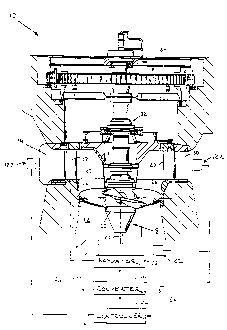
Figure 1 is an elevational view, partially in
cross section, of a hydroelectric installation including a
turbine with adjustable blades;
Figure 2 is a partial schematic side elevational
view of a Prior Art turbine runner;
Figure 3 is a schematic top plan view of the Prior
Art turbine runner of Fig. 2, the adjustable blade shown at
minimum pitch position;
Figure 4 is a partial schematic front elevational
view of the Prior Art turbine runner of Fig. 2 showing two
blade positions;
Figure 5A is a partial schematic cross sectional
view taken along line 5A-5A shown in Fig. 4, illustrating
CA 02217826 1997-10-09
g -
a gap formed between the blade and the hub (in the leading
and trailing edge regions of the blade) at less than maximum
pitch position of the blade;
Figure 5B is a partial schematic cross sectional
view taken along line 5B-5B shown in Fig. 4, illustrating
the reduced gap region between the blade and the hub ( in the
leading and trailing edge regions of the blade) at maximum
pitch position of the blade;
Figure 6 is a side elevational view of a first
embodiment of the hub and one associated blade in accordance
with the present invention, the blade being shown at maximum
pitch position;
Figure 7 is a front elevational view of the first
embodiment shown in Fig. 6, the blade being shown at minimum
pitch position;
Figure 8 is a front elevational view of the first
embodiment shown in Fig. 6, the blade being shown at maximum
pitch position;
Figure 9A is a partial schematic cross sectional
view taken along line 9A-9A shown in Fig. 7, illustrating
that, at less than maximum pitch position of the blade, the
gap formed between the blade and the hub in the leading and
trailing edge regions of the blade is limited to a
functional clearance;
Figure 9B is a partial schematic cross sectional
view taken along line 9B-9B shown in Fig. 7, illustrating
that, at maximum pitch position of the blade, the gap formed
between the blade and the hub in the leading and trailing
edge regions of the blade is also limited to a functional
clearance;
Figure 10 is an enlarged partial doss-sectional
view of a portion of the leading edge of the blade taken
along line l0-to shown in Figure 6;
Figure 11 is a top plan view of a blade of the
present invention showing the spherically-shaped inner
surface of the blade;
Figure 12 is a front elevational view of the hub
and one associated blade in accordance with another
CA 02217826 1997-10-09
- g -
embodiment of the present invention, showing a seal attached
to the inner surface of the blade;
Figure 13 is an enlarged side elevational view of
the blade of Fig. 12 viewed from the inner surface end
thereof, illustrating the seal attached thereto;
Figure 14 is an enlarged partial cross sectional
view taken along line 14-14 of Fig. 13, showing a first
configuration of the blade seal;
Figure 15 is an enlarged partial cross sectional
view taken along line 14-14 of Fig. 13, showing a first
modified configuration of the blade seal;
Figure 16 is an enlarged partial cross sectional
view taken along line 14-14 of Fig. 13, showing a second
modified configuration of the blade seal;
Figure 16A is an enlarged partial cross sectional
view taken along line 14-14 of Fig. 13, showing a third
modified configuration of the blade seal;
Figure 17 is a partial front elevational view of
the hub and blades in accordance with the present invention,
ZO the discharge ring regions of the turbine being shown in
partial sectional view, illustrating the outer surfaces of
the blades conforming to a spherically-shaped discharge
ring;
Figure 18 is a partial sectional view along owa
of the blades rotational axis of a spherically-shaped hub
in accordance with another embodiment of the present
invention, showing the angled linkage connecting the blades
to the blade positioning mechanism;
Figure 19A is a partial sectional view of the
spherically-shaped hub and angled linkage taken along line
19A-19A of Fig. 18;
Figure 19B is a partial sectional view of the
spherically-shaped hub and linkage mechanism taken along
line 19B-19B of Fig. 18;
Figure 20 is an enlarged partial sectional view
of a portion of the angled linkage taken along line 20-20
of Fig. 18 ;
CA 02217826 1997-10-09
- 10 -
Figure 21 is a graphical comparison between the
normalized chordal distribution of a blade in accordance
with another embodiment of the present and that of a prior
art blade; and
Figure 22 is a graphical illustration of the
variation of the clearance gap formed between the blade
outer surface and the face of a discharge ring configured
in accordance with a further aspect of the present.
Detailed Descrit~tion of a Preferred
Exemt~lary Embodiment
The present invention relates generally to
hydroelectric installations having turbines provided with
features designed to reduce gaps formed between the hub and
associated blades, and between the blade outer surfaces or
tips and the discharge ring. Such features are configured
to improve the survivability of fish present in water
flowing through the turbines, reduce cavitation and flow
disturbance, improve the efficiency of the turbine, or
otherwise enhance the operation of the installation. The
turbines are of the Kaplan-type in which several blades
pivotally are connected to the hub. It should be
understood, however, that the invention is applicable to any
other type of turbine or propeller in which the blades are
pivotally adjustable with respect to the hub.
Referring to Figure 1, a hydroelectric turbine
installation generally designated as l0 comprises a
passageway 12, in which water flows from an upper elevation
source in fluid communication with the upstream end 14 of
installation 10, to a lower elevation discharge region 16.
Installation 10 also includes a turbine runner l8 of the
type comprising a hub 20 having a longitudinal axis 22, and
a plurality of runner blades 24 pivotally connected to hub
20. Each blade 24 is movable about a rotational axis 26
extending in a direction generally perpendicular to
longitudinal axis 22. While the present invention will be
described with reference to turbine runner 18 in which
longitudinal axis 22 is vertical as shown in Figure 1, those
CA 02217826 1997-10-09
- 11 -
skilled in the art will appreciate that the present
invention is similarly applicable to turbines disposed
horizontally or at any position deviating from the
horizontal or vertical, depending on the particular
configuration of passageway 12. Furthermore, axes of
rotation 26 could instead be inclined relative to
longitudinal axis 22 (as in "Deriaz" turbines) without in
any way departing from the scope of the present invention.
Intermediate upstream end 14 and rotational axis
26 is disposed a discharge ring 27 which directs the flow
of water from upstream end 14 toward turbine runner 18.
Installation 10 includes a plurality of wicket gates 28,
which may be adjusted in rotation to regulate the flow of
water admitted to passageway 12 , and stay vanes 3 0 which are
designed to support the portion of installation 10 located
above turbine 18, that is, the thrust bearing 32, generator
34, and associated control systems arid components typically
located in the power station, some of these systems
constituting what is commonly known in the industry as the
"governor".
Referring now more particularly to Figures 6-11,
hub 20 comprises an upstream region 36 and a downstream
region 38 located on the upstream and downstream sides of
rotational axis 26, respectively. Turbine runner 18 also
typically includes between 2 and 9 runner blades 24.
However, in most of the Figures only one blade will be
represented to facilitate the description of the present
invention.
Each blade 24 comprises a hydrofoil generally
designated as 40 having an inner surface 42 and a distal
outer surface 44, a leading edge 46 and a trailing edge 48
separated from leading edge 46 by a water directing surface
50 which comprises oppositely facing pressure and suction
sides. For hydraulic considerations, hydrofoil 40 will
usually be twisted as shown in Figure 2 or 7. As a result,
water directing surface 50 can be characterized as having
an inner portion 51, extending from inner surface 42,
CA 02217826 1997-10-09
- 12 -
merging into an outer portion 53 extending to outer surface
44.
Blade 24 is disposed for rotational movement
relative to hub 20 with its inner surface 42 spaced from the
outer surface 52 of hub 20 by functional clearance S. As
more particularly shown in Figure 18, hub 20 is generally
hollow, the hollow cavity 54 being defined by an inner
surface 56 which is spaced apart and oppositely faces outer
surface 52. As will be explained below, cavity 54
conveniently houses the various mechanisms, linkages and
other systems necessary for the rotation of blades 24 about
axes 26. When blade 24 is at minimum pitch position (shown
in Figure 7), outer portion 53 of water directing surface
50 forms a significant impediment to the water flowing
through passageway 12. Toward maximum pitch position (as
illustrated in Figure 8), inner portion 51 of water
directing surface 50 points in a direction generally
parallel to longitudinal axis 22. In other words, blade 24
is "flatter" at minimum pitch position than it is at maximum
pitch position.
In a first embodiment of the present invention,
outer surface 52 of hub 20 swept by inner surfaces 42 of
blades 24 during rotation of blades 24 from maximum to
minimum pitch is spherically shaped forming a spherical
frustum comprising an upstream region 36 and a downstream
region 38. Comparing Figure 6 to a prior art hub
illustrated in Figure 4, it can be readily appreciated that
the included angle 8 formed between the two radiating lines
R is substantially greater in the case of the present
invention than in prior art hubs. Typically, in this first
embodiment of the present invention angle a will be at least
15% larger.
Because the blade inner surfaces 42 are also
spherically shaped and conform to hub outer surface 52,
inner surfaces 42 will substantially conform to outer
surface 52 over the entire range of blade positions,
including at minimum pitch position, thereby limiting the
gap 58 formed therebetween. As illustrated in Figures 9A
CA 02217826 1997-10-09
13
and 9B, over the entire range of blade positions gap 58
remains substantially equal to functional clearance d. Such
an improved spherically-shaped hub therefore eliminates the
large, essentially wedge-shaped gaps 60 typically formed
between the hub and blades at blade pitch position other
than maximum pitch position, as illustrated in Figures 3 and
5A which depict prior art hub configurations. Accordingly,
as discussed earlier, the absence of large gaps 60 therefore
reduces cavitation and flow disturbance, and improves
turbine efficiency and fish survivability.
Typically, a blade inner surface 42 meets'a water
directing surface 50 along a relatively sharp edge.
However, it is well known that sharp edges formed on runner
blades create highly turbulent flows in regions of the water
flow proximate such edges. Accordingly, the present
inventors have also noted that in certain cases it may be
possible to further improve some of these turbine
parameters, and particularly the survivability of fish
passing through turbine runner 18. Toward that end, the
sharp edges of the juncture of inner surface 42 with inner
portion 51 of water directing surface 50, at least in the
region of leading edge 46, may be removed or softened as
required depending on the extent of the overhang of the
blade relative to the hub, or on the size of the gap formed
between the blade and the hub. Such "rounded" configuration
will typically reduce injury to the fish stricken by blade
24 during rotation of hub 20, and will further reduce flow
disturbances in the region of such rounded edges.
Turning now to another embodiment of the present
invention and referring more particularly to Figures 12-16,
it has been found by the inventors that it is possible to
reduce cavitation in Kaplan turbines and improve the
efficiency of such turbine installations, while in both
cases also improving the survivability of fish as they pass
through the turbine, by further preventing water from
flowing into gap 58. To that end, a second embodiment of
the present invention includes a seal 62 attached to inner
surface 42 of blade 24. Seal 62 projecting from inner
CA 02217826 1997-10-09
- 14 -
surface 42 by a predetermined distance dt, d2, or d3 depending
on the size of gap 58 (see Figures 14-16), will effectively
be in contact with outer surface 52 of hub 20 in upstream
and/or downstream regions 36, 38, respectively, that are
swept by blades 24 as they rotate about rotational axes 26.
Referring more particularly to Figures 14-16, seal
62 will be made of a corrosion-resistant or preferably
corrosion-proof material (both being hereinafter generically
referred to as corrosion-resistant materials) such as an
elastomeric material; or an elastomeric material coated with
a friction reducing material such as teflon. Seal 62 may
also be made of a metal such as bronze (e. g., aluminum
bronze) , preferably forming a galling resistant combination
with the material from which hub surface 52 is made. Seal
62, which is advantageously removably attached to inner
surface 42 to facilitate its replacement after extended use
or in the event it becomes damaged, can have one of several
configurations. It can be formed as a continuous strip
extending from the region of the axis of rotation of the
blade to the leading or trailing edge of the blade.
Instead, seal 62 may consist of a plurality of discrete
strip portions.
Whether formed as a continuous strip or discrete
sections, seal 62 can be attached to blade 24 in various
ways. For example, as illustrated in Figure 14, seal 62
which extends from inner surface 42 by a distance di
comprises a first portion 64 made of corrosion-resistant
material and having a recess 66 configured to receive a
fastener 68. Fastener 68 cooperates with a non-pliable
insert 70 designed to evenly distribute the force applied
by fastener 68 to retain first portion 64 into a mating
recess 72 formed in inner surface 42. Seal 62 further
includes a plug 74 made also of corrosion-resistant material
filling cavity 66 and terminating at a point lying
substantially at a distance dl from inner surface 42.
Alternatively and referring now to Figure 15, seal
62 which extends from inner surface 42 by a distance d, may
CA 02217826 1997-10-09
- 15 -
comprise a support portion 76 made of elastomeric material
and disposed below a second portion 78 which is made of a
corrosion-resistant material such as bronze or aluminum
bronze. Seal 62 is removably attached to blade 24 by a
suitably shaped retainer 80 cooperating with a fastener 82.
If required, seal 62 may also include a non-pliable insert
84 to evenly support support portion 76.
A third embodiment of seal 62 is represented in
Figure 16 in which seal 62 extends from inner surface 42 by
a distance d3. In that case, the corrosion-resistant portion
of seal 62 is configured as a truncated pyramid 86 received
in a dove-tail groove 87 and supported by a non-pliable
insert 88. Pyramid 86 is removably attached to blade 24 by
a suitably shaped retainer 90 cooperating with a fastener
92. Alternatively and as shown in Figure 16A, truncated
pyramid 86 may include a cavity 91 to permit pyramid 86 to
be squeezed for installation into groove 87. Once installed
in the groove, cavity 91 is then filled with a curable
liquid compound such as an elastomeric material to prevent
pyramid 86 from become dislodged from groove 87. To permit
removal of the seal when desired, groove 87 is
advantageously provided proximate the blade leading and
trailing edges 46, 48, as applicable, with a retainer such
an expandable locking device designed to prevent slidable
movement of pyramid 86 out of groove 87.
While any of the foregoing embodiments suitably
prevents water from flowing into gap 58, in certain cases
it may be possible to optimize this novel technique. For
example, design considerations may permit reducing the
length of gap 58, i.e., the distance separating the region
of the axis of rotation of the blade from the leading or
trailing edge of the blade. This can be achieved by
enlarging palm 93 of blade 24 as shown in Figure 13, and
consequently the effective length of seal 62 can be
decreased. Other considerations may lead to a reduction of
the size of gaps 94 formed between the outer surface of the
blades and the discharge ring. In those cases, another
CA 02217826 1997-10-09
- 16 -
embodiment of the present invention may be used and will now
be discussed referring more particularly to Figures 17 and
22.
Turbine installation 10 shown in Figure 17
includes a discharge ring 27 disposed in a region of
passageway 12 substantially facing the blades rotational
axes 26. However, it has been recognized in the art of
hydro-power generation that gaps formed between outer
surface 44 and face 96 upstream of blade rotational axis 26
are detrimental to the operation and environmental impact
of the turbine. To address this shortcoming, as illustrated
in Figure 17 wherein to facilitate this explanation
discharge ring 27 is shown in cross-section and the blades
and hub are shown three dimensionally, discharge ring 27 may
have a substantially spherically-shaped face 96 oppositely
facing and swept by outer surfaces 44 of blades 24. As a
result, outer surfaces 44 substantially conform to face 96
as blades 24 are rotated about axes 26 preferably over the
entire range of rotation of blades 24, and as turbine runner
18 rotates about longitudinal axis 22.
While it is preferable for outer surface 44 and
face 96 to conform over the entire area swept by outer faces
44 both upstream and downstream of axis 26, in certain cases
to achieve specified design and operating characteristics
it may be sufficient to have a portion only of outer surface
44 conform to face 96. For example, it may be sufficient
for face 96 to be spherically-shaped only over an area 96a
extending upstream of axis 26 instead of having face 96
(i. e. , areas 96a and 96b) substantially conform to outer
surface 44. Alternatively, it may be acceptable for face
96 to be spherically-shaped only over an area 96b extending
downstream of axis 26. Furthermore, it may also be
acceptable for face 96 to be frusto-spherical, i.e., for
selected portions only of areas 96a and/or 96b to be
spherically-shaped. This configuration may cause a portion
of outer surface 44 to extend beyond (in other words to
overhang) spherically-shaped face 96, in the region of
leading edge 46 and/or trailing edge 48, at certain pitch
CA 02217826 1997-10-09
- 17 -
positions of the blades. We will now turn to Figure 22 to
discuss how these various discharge ring configurations
affect the gap formed therebetween as the blade rotates
about axis 26.
Figure 22 is a graphical representation at maximum
blade tilt of the normalized variation of the radial
clearance i.e., of the gap between the blade outer surface
and the face of the discharge ring, for a blade/discharge
ring combination of the present invention and two prior art
blade/discharge ring configurations. In accordance with
this other embodiment of the present invention, gap 94 is
substantially equal to the functional clearance required
between outer surface 44 and face 96 to permit blade
tilting. In addition and significantly, the present
embodiment causes gap 94 to remain essentially constant and
equal to such functional clearance for all points along
outer surface 44 upstream and downstream of rotational axis
26.
Because discharge ring 27 has an annular
structure, face 96 closely conform with inner surfaces 44
all around discharge ring 27. In such an embodiment of the
present invention, leakage losses are materially reduced as
gaps 58 and 94 are minimized by the cooperation of
oppositely facing~spherically-shaped surfaces, specifically,
by the close conformance of blade inner surface 42 with hub
outer surface 52, and blade outer surface 44 with discharge
ring face 96. This will result in reduced cavitation,
reduced injury to fish passing through the turbine, and
improved efficiency of the turbine installation.
In certain cases, space inside the hollow hub
becomes a dominant consideration. A further embodiment of
the present invention addressing such a situation will now
be discussed referring more particularly to Figures 18-20.
In that case, a linkage mechanism generally designated as
100 is received in hollow hub 20 and connects blades 24 to
a drive mechanism 102 (not shown) for rotation of blades 24
about rotational axes 26. Drive mechanism 102 may consist
of one or several servo-motors, hydraulic cylinder(s), or
CA 02217826 1997-10-09
- 18 -
hydraulic motor(s). Drive mechanism 102 is connected to a
piston head 104 to which linkage mechanisms 100 are
removably connected. In response to an appropriate command
sent to drive mechanism 102, piston head 104 is displaced
within chamber 106, thereby causing rotation of blades 24
about axes 26.
As more particularly illustrated in Figure 18,
linkage mechanism 100 has a longitudinal axis 107 which
forms an included angle with hub axis 22. This "angled"
configuration is used in certain cases to accommodate the
necessary longitudinal displacement of piston head 104 even
though upstream and downstream regions 36, 38, respectively,
are spherically-shaped. Linkage 100 preferably includes
spherical joints generally designated as 108. thereby
facilitating translating movement of piston head 104 into
rotational movement of blades 24. In particular, joints 108
include a pair sphericall~~-shaped bearing portion 110
disposed intermediate a pair of links 112 joining head 104
to blade trunnion generally designated 3s 114. Additional
considerations that may lead to the selection of an angled
linkage mechanism include a relatively small hub diameter
compared to the blade periphery diameter, the number of
blades which as that number increases reduces the sweep of
each blade, or the location of servomotors or other
components necessary to position the blades.
It is well known that the use of turbines with
adjustable blades permits high efficiency output under a
wide range of operating conditions, and in particular under
various "net head" conditions, i.e., under conditions where
the difference between the upper elevation source and lower
elevation discharge region water levels varies widely. Such
broad range of operating conditions typically rea_uires
automatic and simultaneous adjustment of blades 24 and
wicket gates 28 in accordance with load demand. However,
to allow a turbine configured with reduced gaps between the
hub and the inner surface of the blades and between the
outer surface of the blades and the discharge ring as herein
disclosed to maintain its improved cavitation, efficiency,
CA 02217826 1997-10-09
- 19 -
and fish survivability characteristics over this broad
range, the turbine will be advantageously associated with
control systems providing traditional governor functions and
control routines.
Typically, to adjust the position of the blades
and wicket gates it is necessary to sense various parameters
including turbine speed, wicket gate position, blade pitch,
net head, and output power, as the most characteristic ones.
In the early years of Kaplan turbines, sensing of most of
these parameters was done mechanically, as explained in co-
pending U.S. patent application Serial No. 08/623,245, filed
March 28, 1996 which is incorporated herein by reference.
Thus, and referring back to Figure 1, a control
system generally designated as 120 may advantageously be
used with the various embodiments of the present invention.
Control system 120 includes a plurality of sensors 122
designed to measure turbine operation and other related
control parameters. The electric signals generated by
sensors 122 are sent to a controller 124, preferably via
signal conditioning circuits (not shown). For example, the
electrical signal representative of the speed of turbine 18
is provided by a toothed disc mounted on the shaft of
turbine 18; the disc is associated with two inductive
sensing elements providing two independent signals to
controller 120. Controller 124 may also receive an
electrical signal representative of the position of wicket
gate 28. Controller 124 preferably includes a digital-based
processor and required analog to digital conversion and
signal scaling circuits.
The information provided by the various sensors
is then used in control algorithms allowing controller 124
to compute and generate various control signals, as
required, for the efficient operation of installation 10,
without significantly compromising the gains in the fish
survivability, cavitation, and efficiency achieved by the
embodiments) of the present invention that is (are)
associated with control system 120. The control signals
generated by controller 124 are then fed to a plurality of
CA 02217826 1997-10-09
- 20 -
signal converters generally designated as 126. Signals from
each signal converter 126 are sent in the appropriate form
to associated actuators 128 (typically of the hydraulic-
type), used to adjust the position of blades 24 and the
opening of wicket gates 28 , as calculated by controller 124 ,
for efficient operation of turbine installation 10. As a
result, control system 120 provides another way, whether
used alone or in combination with some of the other
embodiments of the present invention, to increase fish
survivability, while increasing efficiency and reducing
cavitation, of an installation having a turbine of the type
disclosed and claimed in this application.
Turning now to a further embodiment of the present
invention and referring to Figures 6 and 21, at times
certain design considerations will not permit increasing
included angle 8 formed between the two radiating lines R.
In other words, it will not be possible to increase upstream
and/or downstream portions 36, 38 of hub 20 to an extent
sufficient to ensure that hub surface 52 swept by inner
surface 42 is spherical. Accordingly, spherical hubs
described in the foregoing may also be conveniently
associated with blades of reduced chordal distance in the
area of the root of the blade, i.e., in the region of the
blade proximat=_ the blade inner surface. However, if
reducing the chordal distance of a contemplated blade design
decreases undesirable gaps formed between the blades and the
hub, such approach also typically reduces the effective
water directing surface of the blade. As a result, to
return the effectiveness of the turbine design to its
original desired value, this approach may require an
increase in the number of blades of the runner.
In particular and as illustrated in Figure 6,
blade 24 is characterized by an upstream chordal
distribution 130 and a downstream chordal distribution 132.
In upstream distribution 130, the upstream chord 134, i.e.,
the distance taken along a perpendicular line extending from
rotational axis 26 to leading edge 46 varies from outer
surface 44 to inner surface 42. Similarly, in downstream
CA 02217826 1997-10-09
- 21 -
distribution 132, downstream chord 136 separating axis 26
from trailing edge 48 varies from outer surface 44 to inner
surface 42. Therefore, in cases where design considerations
will not permit increasing included angle e, another way to
ensure that gaps are not formed as blades 24 depart from
maximum pitch position is to have blades 24 formed with
leading edge 46 extending toward blade rotational axis 26.
This conf iguration is achieved by shortening upstream chord
134 in a root region 138 of blade 24, as shown in Figure 2I.
The effect of shortening chordal distribution 130
in root region 138 can best be understood by referring to
Figure 6 in which is shown a line 140 radiating from the hub
center through the juncture 142 of leading edge 46 and inner
surface 42, and continuing away from inner surface 42 to
intersect leading edge 46 at a forward point 144. In other
words, by extending leading edge 46 toward rotational axis
26 an area 148 is formed, area 148 being bounded by a
portion of leading edge 46 extending between points 142 and
144, and by line 140. As can be readily appreciated, were
leading edge 46 not extending toward axis 26 (as in prior
art cases) , line 140 would intersect leading edge 46 at only
one point, i.e., at point 142. Conversely, the more
significant the chordal reduction in root region 138 the
larger area 148 will become.
Similarly, and as shown in Figure 21, blade 24 may
instead or also include a shortened downstream chord 136 in
root region 138, thereby causing trailing edge 48 to extend
toward rotational axis 26. In such cases, and without
illustrating this similar downstream construction in the
Figures, a radiating line 140' will intersect trailing edge
48 at points 142' and rearwardly at point 144'. In other
words, by extending trailing edge 48 toward rotational axis
26 an area 148' is formed, area 148' being bounded by a
portion of trailing edge 48 extending between points 142'
and 144', and by line 140'.
As those skilled in the art will readily
appreciate, shortening upstream and/or downstream chordal
distances in accordance with the present invention is not
CA 02217826 1997-10-09
- 22 -
a
restricted to certain chordal dimensions, nor is it limited
to certain specific relative dimensional reductions of these
distances. Accordingly and to facilitate a comparison of
the chordal distribution of a blade of the present invention
to that of a prior art blade, one will note that in Figure
21 the chordal distribution has been normalized, both for
the chordal distance and for the radial distance along axis
26, i.e. for any point lying between outer surface 44 and
inner surface 42.
As explained above, shortening upstream chord 134
and/or downstream chord 136, in root region 138 causes blade
inner surface 42 "to fall on", i:e. to lie effectively in
contact with, spherical hub outer surface 52 upstream,
and/or downstream, of blade rotational axis 26., As is
apparent on Figure 6, such blade configuration naturally
enlarges a space 150 formed between leading edge 42 and the
region of hub 20 where upstream region 36 meets the non-
spherical portion 142 of hub 20. However and significantly,
unlike gaps 60, enlarged space 150 will not typically
materially affect the operating characteristics of the
turbine, nor will it increase the propensity of the turbine
to injure fish because, for hydraulic considerations,
leading edge 46 will normally have a rounded profile as
shown in Figure 10.
Finally, according to yet another aspect of the
present invention, spherical hubs and blades of the, types
described herein may also advantageously be used as part of
rehabilitation and other upgrade projects to enhance certain
operating characteristics of existing turbine installations.
In such projects, one of the primary design considerations
is to increase or at least maintain the total water
directing surface area of the turbine runner so as to
increase (or at least maintain) the ability of the blades
to extract energy from the flow of water passing through the
turbine. However, while reducing the chordal distribution
in root region 138 of blade 24 effectively reduces gaps 58
and enhances certain operating characteristics of Kaplan
turbines, as noted above, this approach also reduces the
CA 02217826 1997-10-09
- 23 -
r.
effective water directing surface. Accordingly, in certain
rehabilitation projects it may be desirable to reconfigure
turbine runner 18 by reducing the chordal distance in the
root region of the blades, while increasing the number of
blades to substantially maintain or preferably increase the
power extraction capacity of the turbine.
Specifically, in an existing turbine having M
blades pivotally connected to the hub, each blade comprising
a water directing surface having an inner portion of a given
chordal distance in a root region thereof. To upgrade such
turbine runner, it may be desirable to replace it with a
runner having N improved blades . Each improved blade having
an inner portion of a reduced cho~~dal distance in a root
region thereof. To maintain or preferably increase the
power extraction capacity of the turbine, N is an integer
at leas equal to M times the ratio of the given chordal
distance to the reduced chordal distance.
In light of the foregoing, it should be understood
that the above description is of preferred exemplary
embodiments of the present invention, and that the invention
is not limited to the specific forms described. For
example, those skilled in the art will readily appreciate
that blades 24 could have configurations other than those
described herein provided the inner and outer surfaces of
the blades cooperate with a spherically-shaped hub and/or
discharge ring, respectively. In addition, seal 62 could
be configured or attached to the blade in ways other than
those described. Furthermore, controllers of the type
associated with these improvements do not necessarily need
to be of the digital processor-based type. However, all of
these other constructions are, nevertheless, considered to
be within the scope of this invention. Accordingly, these
and any other substitutions, modifications, changes and
omissions may be made in the design and arrangement of the
elements and in their method of operation as disclosed
herein without departing from the scope of the appended'
claims.