Note : Les descriptions sont présentées dans la langue officielle dans laquelle elles ont été soumises.
~ CA 02218239 1997-10-14
PCT/KR96/00054
SGG- 1191 -CA
DRAIN FORMING EQUIPMENT FOR REINFORCING SOFT
GROUND, AND METHOD AND STRUCTURE FOR
ARRANGING DRAINS
TECHNICAL FIELD
The present invention relates to a technology of reinforcing soft
grounds, and more particularly to a pack for molding a sand pile to form a
drain, a pack guide casing for driving a pack underground, a pack file
driving apparatus which is used for driving a pack into a guide casing, and
a drain structure and an alignment method thereof.
BACKGROUND ART
A vertical draining method such as a flexible sand drain and/or a
paper drain is generally used for reinforcing a soft ground. A conventional
vertical draining method drives a cylindrical guide casing underground,
inserts a sand pack or a paper drain board into the guide casing, and then
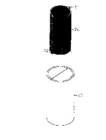
removes the guide casing. FIG. 1 is a perspective view of a flexible sand
pack and a guide casing which are used for a conventional vertical draining
method. As shown in FIG. 1, the conventional vertical draining method is
accomplished by burying a cylindrical guide casing lQ underground, and
then inserting a sand pile molding pack 20 into guide casing 10. The pack
20, which comprises a mesh-type texture, is formed by overlapping two
sheets of the mesh-type textures such that side portions of these sheets
form reinforcement portions 31 and 32 extending lengthwise by connecting
both ends or thermally melting them to attach to each other. Pack 20
-- 1 --
- CA 02218239 1997-10-14
PCT/KR96/00054
SGG- 1191 -CA
inserted into guide casing 10 is filled with sand, and then guide casing 10 is
removed at the sand-filled state to form a drain.
However, the conventional sand pile molding pack has problems that
the manufacturing method is complicated and the manufacturing cost is
high. Also, the conventional molding packs are susceptible to breakage or
cut-off, or some discrepancy between latitude and longitude. Further, the
conventional pack has a problem that the reinforcement portion 31 or 32 is
folded, such that a fine soil cannot pass, and a film is formed which lowers
a draining effect. Also, since the conventional flexible drain is in a
cylindrical shape and the diameter of the drain is limited to a range within
25cm, a draining contact area is small which lowers a draining effect.
The conventional guide casing is formed as only a cylindrical shape, to
accordingly raise a phenomenon of twisting the pack when the pack is
inserted. Moreover, since the paper drain board is a structure of a thin
plate when the paper drain is formed, many spaces are formed therein.
Thus, removal of the casing causes an excessive ground movement.
DISCLOSURE OF THE INVENTION
Therefore, to solve the above problems, it is an object of the present
invention to provide a sand pile molding pack with a simple manufacturing
process and a low manufacturing cost.
Another object of the present invention is to provide a sand pile
molding pack comprising a reinforcement portion in which an electric
conductor is incorporated.
Yet another object of the present invention is to provide a polygonal
CA 02218239 1997-10-14
PCT/KR96/00054
SGG -1191 -CA
sand pile molding pack.
Still another object of the present invention is to provide a pack in
which a flexible sand drain and a paper drain are simultaneously installed.
Still yet another object of the present invention is to provide a pack
guide member in which a pack is not twisted to each other.
A further object of the present invention is to provide a drain including
sand and a reinforcement member for draining acceleration that is buried in
sand.
A yet further object of the present invention is to provide a device for
dropping a reinforcement member.
A still further object of the present invention is to provide a guide
casing which can prevent its bending when buried underground.
A still yet further object of the present invention is to provide a
casing comprising an internal reinforcement member.
Yet another object of the present invention is to provide a drain
structure and an arrangement method thereof in which a draining effect is
high.
Still yet another object of the present invention is to provide a pile
driver for supplying a pack to be driven into a guide casing, so as to form
a plurality of drains being in a rectangular shape.
To accomplish the above obiects of the present invention, there is
provided a pack which is used for reinforcing a soft ground according to an
aspect of the present invention, wherein the pack is fabricated via an
injection molding.
A drain for reinforcing a soft ground according to one feature of the
-- 3 --
- CA 02218239 1997-10-14
PCT/KR96/00054
SGG- 1191 -CA
present invention comprises sand buried underground; and at least one or
more reinforcement members for draining acceleration which is buried in the
sand.
A dropping device of reinforcement members according to another
feature of the present invention comprises a casing, including space inside
for receiving a reinforcement member for draining acceleration and forming
a predetermined size of piercing holes at the top and bottom thereof; and a
fastening member, disposed at the outer of the piercing holes of the casing,
by which one end of the reinforcement portion is fastened.
A guiding pack which is used for reinforcing a soft ground according
to yet another feature of the present invention comprises a first member
which is formed with a hollow shape of a polygonal body having a
predetermined length; and a second member which is connected in the lower
end of the pack and connected to the hollow inside of the first member,
having the same angle as the first member, to be movable up and down.
A guide casing for forming a drain which is used for reinforcing a
soft ground according to still another feature of the present invention
comprises a body, formed in a hollow shape having a predetermined length;
and at least one or more reinforcement members which protrudes in the
body.
A drain structure for reinforcing a soft ground according to still yet
another feature of the present invention, is characterized by the fact that the
drain structure is in a rectangular shape.
A drain arrangement method for reinforcing a soft ground according to
a further feature of the present invention comprises the steps of maint~ining
' ' CA 02218239 1997-10-14
PCT/KR96/00054
SGG- 1191 -CA
a virtual line which connects a center line of each of four rectangular drains
adjacent to each other to form a square, and arranging a longitudinal axis
of each drain perpendicular to the longitudinal axis of an adjacent drain at
the center.
A driving apparatus for forming a drain according to a yet further
feature of the present invention comprises:
a guide bar, installed lengthwise; a driving member, connected to the
guide bar; a driving block, installed in the lower end of the driving member;
a square holding plate which is fixed to the driving block and is in a
rectangular form; a plurality of guide casing which is fixed to the holding
plate and arranged according to the above-described arrangement method;
and a reinforcement connection plate for connecting the guide casings to
each other.
BRIEF DESCRIPTION OF THE DRAWINGS
FIG. 1 is a perspective view of a conventional flexible pack and gide
casing for explaining a vertical draining method.
FIGs. 2A through 2C are views explaining a sand pile molding pack
according to one embodiment of the present invention.
FIGs. 3A through 3F are plan views of a sand pile molding pack
according to another embodiment of the present invention.
FIGs. 4A and 4B are perspective views of a drain according to
embodiments of the present invention.
FIGs. 5A and 5B are perspective views showing a weight material
which is used for dropping a reinforcement member for draining acceleration
-- 5 --
CA 02218239 1997-10-14
PCT/KR96/00054
SGG- 1191 -CA
when forming a drain
FIG. 6 is a perspective view showing a dropping device of a
reinforcement member for draining acceleration according to one embodiment
of the present invention.
FIG. 7 is a perspective view of a guide casing according to one
embodiment of the present invention.
FIG. 8 is a plan view of a guide casing according to another
embodiment of the present invention.
FIGs. 9A through 9D are plan views of guide casings according to yet
another embodiment of the present invention.
FIG. 10 is a plan view of a plurality of integrally constructed guide
casings to embody a drain arranging method according to the present
invention.
FIG. 11 is a conceptual view for explaining a drain arranging method
according to the present invention.
FIG. 12A is a front view of a driving apparatus according to the
present invention, and FIG. 12B is a cross-sectional view taken along a
direction of I-I of FIG. 12A.
FIG. 13A is a perspective view of a conventional flexible drain and
FIG. 13B is a perspective view of a drain structure according to the present
invention.
BEST MODE FOR CARRYING OUT THE INVENTION
Hereinbelow, preferred embodiments of the present invention will be
described in detail with reference to the accompanying drawings.
CA 02218239 1997-10-14
PCT/KR96/00054
SGG- 1191 -CA
FIGs. 2A through 2C are views explaining a sand pile molding pack
according to one embodiment of the present invention. The pack of the
present invention is fabricated by a metal injection molding method. FIG.
2A shows a sand pile molding pack material 50 having a reinforcement
portion 51 at a constant interval which is obtained by the injection molding.
A sand pile molding pack 60 shown in FIG. 2B is obtained by cutting pack
material 50 of FIG. 2A to include at least one reinforcement portion 51 and
combining the cut pack materials with each other.
FIG. 2C is a cross-sectional view of a reinforcement portion of a sand
pile molding pack according to another embodiment of the present invention.
The reinforcement portion 51 in this embodiment includes an electric
conductor 53 therein, which is for connecting an electrode when applying an
electric osmotic method thereto. One electric conductor can be installed for
every reinforcement portion 51 of pack 60, or a plurality of conductors can
be separately installed in a single reinforcement portion.
FIGs. 3A through 3F are plan views of sand pile molding packs
according to yet another embodiments of the present invention. It can be
seen that the packs of the present embodiments are extended lengthwise in
the same pattern despite no showing perspective views.
FIGs. 3A and 3C show rectangular packs and FIGs. 3D and 3F show
cylindrical packs. In these embodiments, the pack includes net portions 71
and a plurality of reinforcement portions 72. The reinforcement portion 72
can be attached to a sub-texture, and then the reinforcement portion 72
attached to the sub-texture is formed to have a bending portion for drain.
Thus, the packs according to these embodiments have a merit that a
-- 7 --
CA 02218239 1997-10-14
PCT/KR96/00054
SGG- 1191 -CA
flexible sand drain and a paper drain can be simultaneously formed.
Further, since the pack is in a rectangular shape, a draining area is
30% greater than a cylindrical pack which consumes the same amount of
sand as that of the rectangular pack. That is, the rectangular pack has
circumferential length of more than 30% at the same area compared with
the cylindrical pack. Thus, an increased draining effect of more than 30%
can be obtained, even though the same amount of sand is used.
Furthermore, the conventional flexible pack is continuously produced
without any marking in the same shape and color, and then is measured
and cut by necessary lengths in use. The drain which is constructed by
using such a pack has an exposed portion of the same shape and color.
Thus, to ascertain whether the underground drain has been constructed up
to a target depth, construction drawings or records should be checked or it
should be measured using other equipment.
Thus, the pack of the present invention has markings which can
identify the length of the pack. That is, when the pack is produced,
various colors or figures are marked on the pack. Alternatively,
reinforcement portions having the identified patterns are made and attached
to the pack to advantageously permit the identification of the length by
human vision. Thus, after construction, identification of the markings of the
exposed drain can make a judgement of whether such a construction was
properly done. Accordingly, poor construction can be prevented, and easy
construction or effective construction control can be performed.
FIGs. 4A and 4B are perspective views of a drain according to
embodiments of the present invention. The drain of the present invention
CA 02218239 1997-10-14
PCT/KR96/00054
SGG- 1191 -CA
includes at least one or more reinforcement members 82 for draining
acceleration at the inside of the sand drain 81. A drain board or a suction
fiber of water can be used as a reinforcement member 82 for draining
acceleration. Thus, This drain can expedite highly drain efficiency and
maintain a certain operation for a long-term time, compared with the
conventional paper drain or sand drain.
FIGs. 5A and 5B are perspective views of a weight material which is
used for dropping a reinforcement member for draining acceleration when
forming a drain. The weight material is fabricated with a rigid material
such as concrete, each of which forms a certain number of connectors 84
according to the number of the reinforcement member for draining
acceleration. Connectors 84 are connected to the bottom of reinforcement
member for draining acceleration. The weight materials can be varied
according to a shape of the guide casing. Protrusions 86 of FIG. 5A are
intended to drop a reinforcement member without occurrence of twist, which
are coupled to a guide groove at the inside of the guide casing (not shown).
FIG. 6 is a perspective view showing a dropping device of a
reinforcement member for draining acceleration according to one embodiment
of the present invention. A dropping unit includes a casing 87, at the top
and bottom of which piercing holes 88 and 89 are respectively formed, and
also forms a gate 90 capable of opening and shutting for putting in and out
reinforcement members. To one end of reinforcement member 82 a
fastening member 91 is coupled. Fastening member 91 which is disposed at
the outer of the top piercing hole 88 of casing 87, is designed to have a
predetermined size not to allow it to pass through piercing holes, and to
CA 02218239 1997-10-14
PCT/KR96/00054
SGG- 1191 -CA
form the drain by filling with sand after fixing the upper end of the
reinforcement member to an inlet for sand. Since fastening member 91 is
for combining the ends of reinforcement member 82, the member 91 does
not depend on any specific shapes as well as format as shown in the
drawing. The other end of reinforcement member 82 is connected to weight
material 92 as shown in FIG. 5, so that reinforcement member 82 can be
swiftly dropping into the inside of a casing for drain formation through the
lower piercing hole 89 without any separate device.
FIG. 7 is a perspective view of a guide casing according to one
embodiment of the present invention.
The casing of the present invention is driven by a predetermined depth
into a soft ground and comprises a first member 95 having a polygonal
body. The casing includes also a second member 96, which is connected to
the bottom of pack P, for guiding swiftly pack P into the inside of first
member 95. Second member 96 has the same angle as first member 95.
Accordingly, when second member 96 is dropped into the inside of first
member 95, the twist and distortion of pack P is prevented.
FIG. 8 is a plan view of the guide casing according to another
embodiment of the present invention. As shown in FIG. 8, guide casing 100
in this embodiment is integrated with at least one or more reinforcement
members 101. The reinforcement member 101 is for bending a paper drain
board 102 and guiding it into the inside of casing 100 or preventing the
bending of a casing. It is more preferable that paper drain board 102 is
made of easily bendable materials at the portions which are shown as
dotted lines. As described above, since paper drain board 102 is bent and
- 10 -
CA 02218239 1997-10-14
PCT/KR96/00054
SGG- 1191 -CA
installed by reinforcement member 101, a wider drain board can be driven
with a smaller cross-sectional area than in the linearly installed case.
Accordingly, a draining effect is largely enhanced and the ground movement
is reduced when driven.
FIGs. 9A through 9D are plan views of guide casings according to
different embodiments of the present invention. As shown in FIGs. 9A
through 9D, guide casings 110 in these embodiments have at least one outer
protrusion 111, respectively. Such protrusions 111 are to prevent bending of
guide casings 110 when guide casings 110 are buried underground,
respectively. In particular, FIG. 9A is a plan view of guide casings 110
consisted of a H-type steel. Here, an intermediate member of H-type steel
plays a part of a reinforcement member 101.
FIG. 10 is a plan view of the pack guide casings in which a plurality
of the pack guide casings are simultaneously buried underground. As can
be seen from the drawing, a plurality of the pack guide casings 160 are
mutually connected by first connectors 161. Thus, bending of the casing can
be prevented when a plurality of the guide casings are simultaneously
driven underground, The dotted lines in the drawing represent second
connectors 162 for effectively preventing the bending of the casing.
FIG. 11 is a conceptual view for explaining a drain arranging method
according to the present invention. As shown in the drawing, the draining
method according to the present invention has processes of maintaining a
virtual line which connects a center point of each drain in four rectangular
drains adjacent to each other to form a square, and of arranging a
longitudinal axis of each drain perpendicular to the longitudinal axis of an
-- 11 --
-
CA 02218239 1997-10-14
PCT/KR96/00054
SGG- 1191 -CA
adjacent drain at the center. Thus, an effective draining radius is balanced
and a ground sink is also expedited since a draining interval is compact.
FIG. 12A is a front view of a driving apparatus according to the
present invention, and FIG. 12B is a cross-sectional view taken along a
direction of I-I of FIG. 12A. As shown in the drawings, the driving
apparatus comprises a guide bar 170, which is vertically installed and to
which a driving member 172 is combined.
At the lower end of driving member 172 a driving block 173 is
installed, to which an approximately rectangular shape of a holding plate 174
is fixed. To holding plate 174 a plurality of guide casings 175A ~ 175D are
fixed, which are connected each other with a reinforcement connection plate
176, to thus prevent distortion of a casing and maintain its vertical state,
thereby constructing a drain having the highest depth. On the other hand,
a guide 177 is coupled to guide bar 170 and forms a hole that allows guide
casings and reinforcement connection plate 176 to pass therethrough, and
plays a role of guiding the direction when guide casings are buried
underground. Therefore, at the upper end of holding plate 174 according to
the driving apparatus, a device for providing sand or a drain board is
optionally installed according to use purpose.
FIG. 12B is a cross-sectional view taken along a direction of I-I of
FIG. 12A. As can be known in the drawing, the driving apparatus of the
present invention provides such a device which can drive simultaneously a
plurality of drains according to the arrangement type of drains shown in
FIG. 11.
FIG. 13A is a perspective view of a conventional flexible drain. The
- 12 -
. ' CA 02218239 1997-10-14
PCT/KR96/00054
SGG- 1191 -CA
flexible drain is in a cylindrical shape and the diameter of the cylindrical
shape is limited to a the range between 5cm ~ 25cm. The reason why the
size of the diameter is limited in a fact that normal draining is not attained
if the diameter is less than 5cm, and the flexibility of the drain is inadequate
if the diameter is greater than 25cm.
FIG. 13B is a perspective view of a drain structure according to the
present invention. The structure of the present invention is in a
rectangular shape, in which the rectangular shape should have a length
between 5cm and 25cm in both sides. Thus, the draining solves the
inadequacy of the flexibility of the drain. Accordingly, when compared with
the conventional apparatus, the present invention provides effects that offers
excellent draining, forms a drain with flexibility in horizontal and vertical
directions, and increases a draining contact surface area with consumption
of a small quantity of sand. That is, under the assumption of the same
height in view of the size shown in the drawings, the drains of FIGs. 13A
and 13B have nearly the same volume, but the FIG. 13B drain has much
larger surface area in view of the circumferential length.
INDUSTRIAL APPLICABILITY
As described above, the present invention provides a new type of
technology for reinforcing a soft ground in which the conventional
drawbacks are completely supplemented.
- 13 -