Note : Les descriptions sont présentées dans la langue officielle dans laquelle elles ont été soumises.
CA 022ls~6 lgg7-lo-l7
W096/33063 PCTlAU~G~1232
CON~T~F,R WITH INTEGRAL ~N~T ~, PREFORM
AND Mb n~ OF MANUFACTURE
INTRODUCTION
This invention relates to a preform from which a
container such as a PET container can be blown and more
particularly to a preform and a container formed therefrom
that has an integral handle.
~-~OUND OF THE lNv~ lON
Attempts have been made to incorporate integral
handles in PET and like injection blow moulded containers -
for example see US 4,629,598 to Thompson, assigned to Tri-
Tech Systems International, Inc. The parison from which
the handled bottles of US 4,629,598 are produced is
illustrated in Fig. 1. To date, however, attempts to
produce a practical, mass produced version of this
arrangement have been unsuccessful. Instead, the best that
appears to have been done in commercial practice is an
arrangement whereby the blown containers arç arranged to
accept a clip on or snap on handle in a separate production
step after the container itself is formed. See for example
WO82/02371 and W082/02370, both to Thompson.
Injection-stretch-blow moulding is a process in which
the parison is stretched both axially and radially,
resulting in biaxial orientation.
Biaxial orientation provides increased tensile
strength (top load), less permeation due to tighter
CA 02218~6 1997-10-17
WO9~/3~063 PCT/AU96/00232
alignment of the molecules, and improved drop impact,
clarity, and lightweighting of the container.
Not all thermoplastics can be oriented. The major
thermoplastics used are polyethylene terephthalate (PET),
polyacrylonitrile (PAN), polyvinyl chloride (PVC), and
polypropylene (PP). PET is by far the largest volume
material, followed by PVC, PP, and PAN.
The amorphous materials, e.g., PET, with a wide range
of thermoplasticity are easier to stretch-blow than the
partially crystalline types such as PP. Approximate melt
and stretch temperatures to yield maximum container
properties are:
~aterial Melt, Degrees C. ~tretch, Degrees C.
PET 280 107
PVC 180 120
PAN 210 120
PP 240 160
There are basically two types of processes for
stretch-blow moulding: 1) single-stage in which preforms
are made and bottles blown on the same machine, and 2) two-
stage in which preforms are made on one machine and blown
later on another machine.
Single-stage equipment is capable of processing PVC,
PET, and PP. once the parison is formed (either extruded
or injection moulded), it passes through conditioning
stations which bring it to the proper orientation
temperature. The single-stage system allows the process to
proceed from raw material to finished product in one
machine, but since tooling cannot be easily changed, the
process is best suited for dedicated applications and low
volumes.
-
CA 02218~6 1997-10-17
W096/33063 PCTIAU96100232
Oriented PVC containers most commonly are made on
single-stage, extrusion-type machines. The parison is
extruded on either single- or double-head units.
Temperature conditioning, stretching, and thread forming
are done in a variety of ways depending on the design of
the machine. Many of the processes presently in use are
proprietary.
Many oriented PET containers are produced on single-
stage machines. Preforms are first injection moulded, then
transferred to a temperature conditioning station, then to
the blow moulding operation where the preforms are stretch-
blown into bottles, and finally to an eject station.
With the two-stage process, processing parameters for
both preform manufacturing and bottle blowing can be
optimized. A processor does not have to make compromises
for preform design and weight, production rates, and bottle
quality as he does on single-stage equipment. He can
either make or buy preforms. And if he chooses to make
them, he can do so in one or more locations suitable to his
market. Both high-output machines and low output machines
are available. Two stage extrusion-type machines generally
are used to make oriented PP bottles. In a typical
process, preforms are re-extruded, cooled, cut to length,
reheated, stretched while the neck finish is being trimmed,
and ejected. The two-stage process is the lowest-cost
method to produce oriented PET containers. The two-stage
process, which permits injection moulding of the preform
and then shipping to blow moulding locations, has allowed
companies to become preform producers and to sell to blow
moulding producers. Thus companies that wish to enter the
market with oriented PET containers can minimise their
capital requirements. Two-stage stretch-blow moulding also
is being used for production of oriented PVC containers.
Preform design and its relationship to the final container
remains the most critical factor. The proper stretch
ratios in the axial and hoop directions must be met if the
container is to properly package its intended product.
CA 022ls~6 lgg7-lo-l7
W09~33S3 PCTIAU96/00232
--4--
Material 8tretch Ratios Orientation Temp.Deg.F
PET 16/1 195-240
PVC 7/1 210-240
PAN 9/1 220-260
PP 6/1 260-280
It is an object of the present invention to produce a
practical, readily implementable injection, stretch blow
moulded container made from an orientable thermoplastics
material incorporating a handle which is formed during and
as part of the said injection, stretch blow moulding
operation.
8UMMARY OF THE lNv~ lON
According to one aspect of the invention, there is
provided a preform for a container comprised of orientable
thermoplastic material and arranged so that the resultant
blown container will include a handle or like support
structure; said preform comprising a moulded structure
having a neck portion and an expandable portion below the
neck, said neck including a locating ring above the
expandable portion and a solid stem of orientable
thermoplastics material projecting from the locating ring
and moulded integrally therewith which when the container
is formed constitutes the handle.
Preferably said stem projects from said locating ring
and from a temperature transition zone located immediately
below said ring.
According to another aspect of the invention there is
provided a method of forming a container having an integral
handle; said method comprising:
(a) forming a preform having a neck portion and an
expandable portion below the neck portion, said neck
portion including a locating ring above the expandable
portion and a solid stem of orientable thermoplastics
material projecting from the locating ring and moulded
integrally therewith, and
CA 02218~6 1997-10-17
WO ~f 'Y 53 PCr/AU96100232
(b) performing a blow moulding operation on said
preform to expand the expandable portion to form the body
of the container.
Preferably said stem projects from said locating ring
and from a temperature transition zone located immediately
~ below said ring.
In a preferred form of the invention, the neck portion
and integral handle are subjected to a crystallisation
step.
Preferably, the blow moulding operation includes
supporting the stem whilst the preform is blown in a manner
whereby at least a portion of the external side of the tube
expands to encircle at least a lower portion of the stem so
as to form an enclosed grip portion between the external
side and the solid stem.
It is preferred that the enclosed grip portion allows
at least two fingers of the adult human hand to pass
therethrough.
In a particularly preferred form of the invention the
stem is formed so as to have an I-shaped cross-section at
least throughout that portion of the stem where it projects
from the external side of said tube. The handle may be
curved to provide additional strength.
In a further broad form of the invention there is
provided a parison for an injection stretch blow moulding
process, said parison formed by an injection process
including two separate points of injection.
Preferably a first point of injection permits
injection of non-recycled PET or like thermoplastics
material. Preferably a second point of injection permits
injection of PET or like thermoplastics material
incorporating at least a portion of recycled material.
Preferably said first point of injection is for the
formation of that part of the parison which will be
stretched during a stretch blow moulding operation on the
parison. Preferably said second point of injection is for
the formation of those parts of said parison which will
CA 02218~6 1997-10-17
WO 96/33063 PCT/AU~15.'0C232
remain unexpanded or substantially unexpanded in a stretch
blow moulding operation on said parison.
In yet a further broad form of the invention there is
provided a container manufactured from a two stage D
injection stretch blow moulding process, said container
including a graspable handle affixed at at least a first
point and a second point to said container so as to form an
enclosed area between the handle and the bottle and through
which the fingers of a human hand may be passed.
Preferably said first point of connection comprises an
integral connection between the handle and the container
and is formed in said first step of said two step
operation.
Preferably said second point of connection is formed
during said second step of said two step operation.
Preferably said handle at said second point of
interconnection includes a bulbous portion adapted to be at
least partially enfolded by a portion of said container as
it is blown during said second step of said two step
operation whereby a mechanically interlocked connection is
formed at said second point of connection of said handle to
said container.
In particular preferred forms said bulbous portion
comprises one of an upwardly extending hook, a downwardly
extending hook, a bulb or a combination of one or more
thereof.
BRIEF DE~CRIPTION OF THE DRAWING8
Embodiments of the present invention will now be
described by way of example, with reference to the
accompanying drawings, in which:
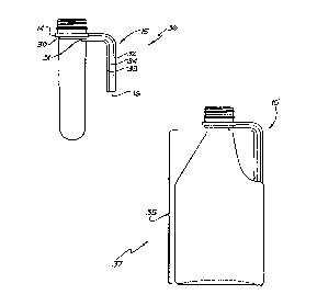
Fig. 1 is a side view of a prior art parison,
Fig. 2 is a side view of a parison incorporating features
according to embodiments of the present invention,
Fig. 3 is a partial side elevational view of a blow moulded
PET container formed from a preform according to one
embodiment of the invention;
CA 02218~6 1997-10-17
WO 96/33063 PCT)AU96JI)D232
Fig. 4 illustrates the steps of formation of a parison
according to another embodiment of the invention.
Fig. 5A is a side view of a preform according to a further
embodiment of the invention;
Fig. 5B is a side view of a container formed from the
preform of Fig. 5A.
Fig. 6 is a side view of a die in open position for
manufacture of a preform;
Fig. 7 is the die of Fig. 6 in closed position and
Fig. 8 is a side view of the die of Figs. 6 and 7 showing
the stem of the preform located therein.
DETATT.~n DE8CRIPTION OF THE DRAWING~
A container 10 according to an embodiment of the
invention is shown in Fig. 3. It includes a neck 11 and an
expanded portion 12.
The neck 11 has a threaded portion 13 and a locating
ring 14. Moulded integrally with the ring 14 is a stem 15
having a first portion 15a extending outwardly from the
ring 14 and a second portion 15b so inclined to the first
portion 15a that it is nearly parallel to a vertical axis
of the container 10. In this instance, the first portion
15a subtends an angle of slightly more than 45~ to the wall
20 and the second portion subtends an angle of about 20~ to
the wall 20.
The particular shape of the stem 15 is selected so
that when formed as a handle it may be grasped by fingers
of the human hand.
The stem 15 terminates in a stem end 16 which faces
generally downwardly in the general direction of closed end
of the container 10.
In this instance, the stem 15 is of I-shaped cross-
section to combat unwanted effects arising at or near
; junction 17 of stem 15 with the ring 14 following a blowing
operation on the preform 10.
CA b22ls~6 lgg7-lo-l7
W096/33063 PCT/AU9''~C232
These unwanted effects particularly include stress
effects and air inclusions resulting from non-uniform
cooling through preform volumes of differing cross-section.
In this embodiment of the invention, the preform is
made from PET and is prepared utilizing a heated mould.
In order to produce the container 10, the parison or
preform 26 (see Fig. 2) according to an embodiment of the
invention can be placed in a blow moulding machine (not
shown) and blow moulded according to bi-axial orientation
blow moulding techniques with the neck 11 being held in a
mould in such a way as not to expand. Initially, the
expandable portion of the preform below the neck can be
mechanically stretched downwardly to the bottom of the
mould and then the bulk of the preform can be blown
outwardly by application of compressed air to the extent
that a support portion 18 is formed around the stem end 16
such that an enclosed area 19 is formed between wall 20 of
the container 10 and the stem 15 in the process of the
formation by blow moulding of container 10.
In a particular preferred form of the invention, the
enclosed area 19 is of sufficient cross-sectional area to
allow at least two fingers of a human hand to be inserted
therethrough and to grasp handle 15 so as to support the
container 10.
The blow moulding operation is carried out in such a
way so as to provide a bottle or container having optimum
strength by achieving biaxial orientation of the molecules
of the preferred PET material as well as improved barrier
properties to reduce oxidation.
In accordance with an embodiment of the invention, the
neck 11 and handle 15 can be crystallised by over-heating
those parts of the preform. The crystallisation of the
handle increases its rigidity which assists orientation of
the preform and permits the use of less material.
Crystallisation of the neck and handle can be carried
out by running hot oil over the neck and handle, applying
an open flame or by blowing hot air.
CA 02218~6 1997-10-17
W096/33063 PCTIAU96100232
The location of the handle 15 on the ring 14 ensures
that there is minimum interference to the blow moulding
process applied to the remainder of the preform. Either a
one stage or two stage process can be used.
Detailed DescriPtion of Further Embodiments
Fig. 1 illustrates the prior art preform or parison 21
of US 4,629,598. The concept of this prior art disclosure
is to form a handle portion 23 from the locating ring of
non-expandable portion 22 of the parison 21.
With reference to Fig. 2 and with reference to the
detailed description of the preferred embodiment this
arrangement of Fig. 1 is modified according to the present
invention in a number of respects.
Insets 2A, 2B and 2C show bulbous portions 27 forming
part of stem end 16 in the shape, respectively of a
downwardly extending hook 24a, a bulb 24b and an upwardly
extending hook 24c.
These portions have in common a shape which is adapted
to engage mechanically with a blown portion of the
container lO which is adapted to envelop the bulbous
portion 27.
The process by which the second stage blow of the
expandable portion 12 of parison 26 is effected so as to
envelope the bulbous portion 27 of stem end 16 is a stretch
blow, biaxial orientation process.
With reference to Fig. 4 a particular method of
manufacture of the parison 26 according to another
embodiment of the invention is illustrated. It includes a
two stage process for the formation of the parison by an
injection moulding process. In Stage 1 a first injection
mould inlet 28 permits entry of plastics material for the
formation of the expanded portion 12 of the parison 26
(expanded in the blow moulding stage of container
formation, with reference to Fig. 3).
In a second stage of the injection moulding process
for the formation of parison 26 a second injection mould
CA 02218~6 1997-10-17
WO 9G/3~Q~ PCT/AU~GI~~232
--10--
inlet 29 permits entry of plastics material for the
formation of the non-expandable portion 25 of parison 26.
The two stage injection arrangement is such that
different plastics materials may be injected through first
injection mould inlet 28 and second injection mould inlet
29.
In a particular preferred form the plastics material
injected in first injection mould inlet 28 is non-recycled
or substantially non-recycled plastics material whilst the
plastics material injected into second injection mould
inlet 29 is recycled or at least partially recycled
plastics material.
This arrangement permits controlled use of proportions
of recycled and non-recycled plastics material in order to
achieve optimum economics in the construction of parison
26.
In a modification of this arrangement the Stage 2 step
can include the production of two walls in the non-
expandable portion 25 comprising inner wall 51 and outer
wall 52. Inner wall 51 is made from virgin or non-
contA ;n~ted PET material and acts as an insulation barrier
with respect to wall 52 which can be made from recycled
material 52. This dual wall arrangement can be produced by
use of a sliding core arrangement as a modification in the
die arrangement and process described with reference to
Figs. 6, 7 and 8 later in this specification.
of course the Stage 1 and Stage 2 steps of Fig. 4 can
be interchanged in order.
A parison and resulting container according to a
further embodiment of the invention are illustrated in
Figs. 5A and B respectively. Like parts are numbered as
for previous embodiments.
In this embodiment the parison 21 includes a locating
ring 14 immediately below which is a first non-expanding
region 30 and a second non-expanding region 31. The first
non-expanding region 30 may itself be formed so as to be
slightly raised or otherwise differentiated from the
CA 02218~6 1997-10-17
WO9C~33~3 PCr/AU96/00232
--11--
expandable portion of parison 21. Second non-expanding
region 31 may not be differentiated from the expandable
portion of parison 21 but, in use, the blowing operation
~ will be such as to ensure that the second non-expanding
region 31 is not expanded in the blowing process.
In this case the stem 15 includes a first rib 32
integrally moulded with and extending from locating ring
14. The stem 15 also includes second rib 33 integrally
moulded with and extending from second non-expanding region
31. Stem 15 further includes a rib connector 34 integrally
moulded with and extending from first non-expanding region
30 and forming a continuous connection between first rib 32
and second rib 33 throughout the length of stem 15.
The parison 36 of Fig. 5A is then blown in the manner
previously described to form the volume 35 of container 37
illustrated in Fig. 5B. The neck portion including stem
15, ring 14, first non-expanding region 30 and second non-
expanding region 31 remain unexpanded whilst the expandable
portion 36 of parison 36 is biaxially stretched to form the
major volume 35 of container 37. The stem end 16 may
include the bulbous portions according to the previously
described embodiments for connection to container 37 or,
either alternatively or in addition can include the
application of an adhesive material whereby a chemical bond
is formed between stem end 16 and the wall of container 37
by the use of a chemical intermediary.
In a modification of the embodiments of Fig. 5A and
Fig. 5B first non-expanding region 30 and second non-
expanding region 31 can form part of a single non-expanding
region.
In yet a further modification second non-expanding
t region 31 can be located in the temperature transition zone
of the container and wherein minor expansion during the
blow moulding step may take place.
In yet a further modification both first non-expanding
region 30 and second non-expanding region 31 may be located
in the temperature transition zone immediately below the
CA 02218~6 1997-10-17
WO 96/33063 PCT/AU~IC1~232
--12--
locating ring 14 and, again, minor expansion of these
regions may take place during blowing.
With respect to the last two variations described
advantage is taken of the observation that expansion at the
temperature transition zone can be limited by appropriate
mould design and process control whereby unwanted
distortion effects caused by the rigid interconnection of
this temperature transition zone 30, 31 via second rib 33
and rib connector 34 to ring 14 (or other non-expanding
portion of the neck 11) can be controlled.
In use preforms and containers blown therefrom can be
manufactured as follows:
A preform is formed from orientable thermoplastics
material, preferably PET or like material in an injection
moulding process. Slidable dies are illustrated in Figs.
6, 7 and 8 and include a sliding core 40, sliding blocks
41, body 42, base 43, push block 44 and splits holder 45.
Fig. 6 illustrates the die in open position, Fig. 7
illustrates the die in closed position and Fig. 8
20 illustrates a side view showing accommodation of the stem
14.
The completed preforms in a second and preferably
separate step are subsequently passed to a stretch blow
mould machine where the preforms are first reheated to the
appropriate transition temperature (refer introduction).
The non-expandable portion of the preform including
locating ring 14 and stem 15 are shielded substantially
from the reheat process by appropriate guarding. In most
instances there is likely to be a temperature transition
zone in the region 30, 31 described with reference to Figs.
5A, 5B.
The reheated preform is then placed in a mould and
biaxially stretched and the expandable portion blown to
full size utilising processes known in the art. During
this process the preform is supported at neck 14 and may
also be supported at stem 15. Stem 15 does not take part
in the blow process although its stem end 16 may be
CA 02218~6 1997-10-17
WO 96/33063 ~CIIAU96100232
partially enveloped by an external wall of the blown
container.
The above describes only some embodiments of the
present invention and modifications obvious to those
skilled in the art can be made thereto without departing
from the scope and spirit of the present invention.
INDU8TRIAL APPLICABILITY
Embodiments of the invention are applicable to the
manufacture of containers made from orientable
thermoplastics material and incorporating a handle or like
grasping fixture as an integral component of the container.