Note : Les descriptions sont présentées dans la langue officielle dans laquelle elles ont été soumises.
CA 02219259 2001-04-19
-1-
Title of the Invention
LOCKABLE TELESCOPING SCREWDRIVER
Scope of the Invention
This invention relates generally to a screwdriver for driving collated
screws which are joined together in a strip, and, more particularly, to a
power
screwdriver with a slide body which extends and retracts in driving collated
screws and
which can be maintained in a retracted position.
Background of the Invention
Collated screwstrips are known in which the screws are connected to
each other by a holding strip of plastic material. Such strips are taught, for
example,
by U.S. Patent 4,167,229 issued September 11, 1979 and its related Canadian
Patents
1,040,600 and 1,054,982 as well as U.S. Patent 4,930,630. Screws carried in
such
screwstrips are adapted to be successively incrementally advanced to a
position in
alignment with and to be engaged by a bit of a reciprocating, rotating power
screwdriver and screwed into a workpiece. In the course of the bit engaging
the
screws and driving it into a workpiece, the screw becomes detached from the
plastic
holding strip leaving the strip as a continuous length.
In the use of such collated screwstrips in screwdrivers, the strip serves
a function of assisting in guiding the screw into a workpiece and, to
accomplish this,
the holding strip is retained against movement towards the workpiece. In the
screwstrip, each screw to be driven has its threaded shaft threadably engaged
in a
threaded sleeve of the holding strip such that on the screwdriver engaging and
rotating
each successive screw, the screw turns within the sleeve which acts to guide
the screw
as it moves forwardly into threaded engagement into the workpiece. Preferably,
only
after the tip of the screw becomes engaged in the workpiece, does the head of
the screw
CA 02219259 2001-04-19
-2-
come into contact with the sleeves. Further, forward movement of the screw
into the
workpiece then draws the head downwardly to engage the sleeve and to rupture
the
sleeve by reason of the forward movement of the head with the strip retained
against
movement towards the workpiece. The sleeve preferably is configured to have
fragile
straps which break on the head passing through the sleeve such that the
holding strip
remains intact as a continuous length. Since the holding strip is a continuous
length,
on advancing the screwstrip with each successive screw to be driven, it
necessarily
results that portion of the holding strip from which each screw has been
driven are also
advanced to exit from the power screwdriver.
Known power screwdrivers for driving such collated screwstrips include
U.S. Patent 4,146,071 to Mueller et al, issued March 27, 1976, and U.S. Patent
5,186,085 to Monacelli, issued February 16, 1993. Such known power
screwdrivers
include a rotatable and reciprocally moving screwdriver shaft which is turned
in
rotation by an electric motor. A screwdriving bit forms a forwardmost portion
of the
shaft for engaging the head of each successive screw as each screw is moved
into a
driving position, axially aligned under the screwdriver shaft.
Known power screwdrivers for collated screwstrips suffer the
disadvantage appreciated by the applicant that they are dedicated to drive
collated
screws. In use, they cannot be used to drive separate screws or to withdraw
mis-driven
screws or other screws which are desired to be removed. Known power
screwdrivers
for collated screwstrips also suffer the disadvantage that it is difficult to
engage and
change bits mounted to the front end of the drive shaft.
Summary of the Invention
To at least partially overcome these disadvantages of previously known
screwdrivers, the present invention provides a power screwdriver for collated
CA 02219259 1997-10-23
-3-
screwstrips which may be latched or locked in a retracted position for use as
a
normal power screwdriver so as to drive separate screws and/or to withdraw
screws
and the like independently of the collated screwstrip.
An object of the present invention is to provide a power screwdriver
adapted for driving collated screws which may be latched in an extension
limiting
position in which the screwdriver may be used independently of the collated
screwstrip.
Another object is to provide a screwdriver for collated screws which
permits latching in a position for use as a screwdriver with or without the
collated
screwstrip engaged in the screwdriver assembly.
Another object is to provide a screwdriver for collated screwstrips
which may be latched in a position permitting access to the drive shaft and/or
bit for
facilitating removal and/or changing of the bit and/or to permit manual
engagement
with the bit of screws separate from the collated screwstrip.
Accordingly, the present invention provides a power screwdriver
attachment for driving collated screws having a housing and a slide body
movable
between extended and retracted positions to drive screws from a collated
screwstrip,
a latching system to releaseably latch the slide body in an extension limiting
position
in which the power driver is able to be used as a power screwdriver
independent of
the collated screwstrip. The screwdriver attachment may be used as a power
screwdriver for driving or withdrawing screws whether or not a screwstrip is
engaged
in the attachment. When latched, the screwdriver attachment permits the
collated
screwstrip to be withdrawn or inserted and, as well, permits the drive shaft
to be
rotated either forwardly or rearwardly. The screwdriver attachment preferably
has
a depth adjustment mechanism to adjust the extent to which any screw is driven
into
a workpiece and which mechanism remains operative when the attachment is
latched
in the extension limiting position. In the extension limiting position, a bit
carried on
a forward end of a driver shaft is preferably accessible for manual engagement
of
CA 02219259 2000-11-20
-4-
separate screws thereon to permit driving or removal of such separate screws
with
the power screwdriver attachment. The latching system preferably is readily
manually accessible to a person using the power tool.
The construction of the screwdriver is preferably compact and
lightweight. A compact design may be achieved by caroming portions of the
slide
body extending within the housing rearwardly past the coupling of the housing
to the
power driver. A lightweight design utilizes lightweight synthetic plastic and
nylon
materials to comprise major portions of the element.
In one aspect, the present invention provides an apparatus for driving
with a power driver a screwstrip comprising threaded fasteners such as screws
or the
like, which are joined together in a strip comprising:
a housing;
an elongate drive shaft for operative connection to a power driver for
rotation thereby and defining a longitudinal axis;
a slide body coupled to the housing for displacement parallel to the
axis of the drive shaft between an extended position and a retracted position;
a spring biasing said slide body forwardly relative to the housing
parallel to the axis to the extended position;
screw feed advance mechanism to engage the screwstrip and
successively, incrementally advance screws on the screwstrip to be axially in
alignment with said drive shaft for driving of the screws by the drive shaft,
and
the screw feed advance mechanism coupled between the slide body and
the housing whereby displacement of the slide body relative the housing
between the
extended position and the retracted position activates the screw feed advance
mechanism to advance successive screws;
an extension limit mechanism activatable to releasably prevent the
housing and slide body from being extended relative each other towards the
extended
position beyond an extension limit position. The extension limit mechanism
may,
CA 02219259 2000-11-20
-5-
in one aspect, lock the housing and slide body together against relative
movement.
Preferably, the slide body has a guide channel mechanism for said screwstrip
extending through the slide body,
a guide mechanism to locate successive of the screws advanced via the
guide channel to be axially in alignment with said drive shaft for engagement
in
driving of the screws from the guide mechanism by the drive shaft, and
screw feed advance mechanism to engage the screwstrip and
successively, incrementally advance screws on the screwstrip through the guide
channel mechanism.
In another aspect, the present invention provides an apparatus for
driving with a power driver a screwstrip comprising threaded fasteners such as
screws or the like, which are joined together in a strip comprising:
housing means;
elongate drive shaft means for operative connection to a power driver
for rotation thereby and defining a longitudinal axis;
slide body means coupled to the housing means for displacement
parallel to the axis of the drive shaft means between an extended position and
a
retracted position;
spring means biasing said slide body means forwardly relative to the
housing means parallel the axis to the extended position;
screw feed advance means to engage the screwstrip and successively,
incrementally advance fasteners on the screwstrip into axial alignment with
said drive
shaft means for driving of successive fasteners by the drive shaft means;
the screw feed advance means coupled between the slide body means
and the housing means whereby displacement of the slide body means relative
the
housing means between the extended position and the retracted position
activates the
screw feed advance means to advance successive fasteners;
CA 02219259 2000-11-20
-Sa-
extension limit means activatable to releaseably prevent the housing
means and slide body means from being extended relative each other towards the
extended position beyond an extension limit position;
wherein the extension limit means comprises first catch means on the
slide body means and second catch means on the housing means, one of the first
and
second catch means being manually adjustable to assume either an activated or
an
inactivated position;
wherein with the adjustable one of the first and second catch means in
the activated position, when the slide body means and housing means are
retracted
beyond the extension limit position, the first and second catch means are
engageable
to prevent the housing means and slide body means from being extended relative
each
other beyond the extension limit position, and
wherein with the adjustable one of the first and second catch means in
the inactivated position, the first and second catch means do not engage to
impede
relative sliding of the housing means and the slide body means.
In another aspect, the present invention provides an apparatus for
driving with a power driver a screwstrip comprising a length of holding strip
holding
a plurality of threaded fasteners in a row in spaced side by side relation
comprising:
housing means;
elongate drive shaft with a rearmost end for operative connection to a
power driver for rotation thereby and a forwardmost end carrying a fastener
engaging
bit, the drive shaft defining a longitudinal axis;
a slide body coupled to the housing for displacement parallel to the
axis of the drive shaft between an extended position and a retracted position;
a screw feed advance mechanism to engage the screwstrip and
successively, incrementally advance fasteners on the holding strip in a
direction
transverse the axis into axial alignment with said drive shaft for driving of
successive
fasteners by the bit forwardly from the holding strip and into a workpiece
while
maintaining the length of the holding strip unsevered;
CA 02219259 2000-11-20
- Sb -
an extension limit mechanism activatable to releaseably prevent the
housing and slide body from being extended relative each other towards the
extended
position beyond an extension limit position in which the bit is located
forward of the
holding strip.
In another aspect, the present invention provides an apparatus for
driving with a power driver a screwstrip comprising a length of holding strip
holding
a plurality of threaded fasteners in a row in spaced side by side relation
comprising:
a housing;
elongate drive shaft with a rearmost end for operative connection to a
power driver for rotation thereby and a forwardmost end carrying a fastener
engaging
bit, the drive shaft defining a longitudinal axis;
a slide body coupled to the housing for displacement parallel to the
axis of the drive shaft between an forward position and a rearward retracted
position;
the slide body carrying guide means about the axis to receive
successive of the fasteners in the holding strip axially in alignment with the
drive
shaft for driving forwardly by the bit out of the holding strip and from the
guide
means,
the slide body also carrying a guide channel extending transversely to
the axis to guide the holding strip containing fasteners into the guide means,
an extension limit mechanism activatable to releaseably prevent the
housing and slide body from being extended relative each other towards the
extended
position beyond an extension limit position in which the bit is located
forward from
the holding strip received in the guide means.
In another aspect, the present invention provides an apparatus for
driving with a power driver a screwstrip comprising threaded fasteners such as
screws
or the like, which are joined together in a holding strip comprising:
a housing;
an elongate drive shaft for operative connection to a power driver for
rotation thereby and defining a longitudinal axis;
CA 02219259 2000-11-20
- SC -
a slide body coupled to the housing for displacement parallel to the
axis of the drive shaft between an extended position and a retracted position;
a screw feed advance mechanism to engage the screwstrip and
successively, incrementally advance fasteners on the screwstrip into axial
alignment
with said drive shaft for driving of successive fasteners by the drive shaft;
an extension limit mechanism activatable to assume an activated
configuration and an inactivated configuration,
in the inactivated configuration, the extension limit mechanism does
not impede relative sliding of the housing and the slide body,
in the activated configuration, when the housing and slide body are
retracted beyond an extension limit position, the extension limit mechanism
prevents
the housing and slide body from being extended relative each other towards the
extended position beyond the extension limit position,
in the activated configuration, the extension limit mechanism does not
impede relative sliding of the housing and the slide body towards the
retracted
position.
Brief Description of the Drawings
Further aspects and advantages of the present invention will appear
from the following description taken together with the accompanying drawings,
in
which:
Figure 1 is a pictorial view of a power screwdriver in accordance with
a first embodiment of the present invention;
Figure 2 is an exploded pictorial view of the housing and slide body
shown in Figure 1;
Figure 3 is a pictorial view of the opposite side of the slide body to
that shown in Figure 2 but with a screwstrip positioned therein;
Figure 4 is a schematic partially cross-sectional view of the driver
attachment of Figure 1 in a fully extended position as seen in Figure 1
through a
CA 02219259 2000-11-20
-Sd -
plane passing through the longitudinal axis of the drive shaft and centrally
of the
screws in the screwstrip;
Figure 5 is a view identical to Figure 4 but with the driver attachment
in a partially retracted position in driving a screw into a workpiece;
Figure 6 is an end view of the nose portion of Figure 2;
CA 02219259 1997-10-23
-6-
Figure 7 is a view identical to Figure 4 but with the driver attachment
in a more retracted, extension limit position;
Figure 8 is a schematic cross-sectional view of the driver attachment
of Figure 7 along lines 8-8' and with the nose portion removed;
Figures 9, 10 and 11 are respectively, side, top and front views of the
latch member shown in Figure 8;
Figure 12 is an enlarged cross-sectional view of the housing alone as
seen along line 8-8' of Figure 7 in the absence of the other components;
Figure 13 is an enlarged side view of the righthand side of Figure 8,
however, showing the housing alone;
Figure 14 is a schematic pictorial view of another version of a
removable nose portion with a segment of a screwstrip;
Figure 15 is a partially cut-away pictorial view of the nose portion of
Figure 14 from a different perspective.
Detailed Description of the Drawings
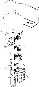
Reference is made to Figure 1 which shows a complete power
screwdriver assembly 10 in accordance with the present invention. The assembly
10
comprises a power driver 11 to which a driver attachment 12 is secured. The
driver
attachment 12 engages a collated screwstrip 14 with spaced screws 16 to be
successively driven.
Reference is made to Figure 2 showing an exploded view of major
components of the driver attachment 12 as housing 18 and a slide body
comprising
a rear portion 22 and a removable nose portion 24. Figures 4 and 5 show in
cross-
section the interaction of these components.
As seen in Figure 4, the rearmost end 26 of the housing 18 has a
rearwardly directed socket 27 with a longitudinal slot 28 in its side wall to
receive
and securely clamp the housing 18 onto the housing 30 of the power driver 11
sows
CA 02219259 1997-10-23
_7_
to secure the housing 18 of the driver attachment to the housing 30 of the
power
driver against relative movement. The power driver 11 has a chuck 32 rotatable
in
the driver housing 30 by an electric motor (not shown). The chuck 32
releasably
engages the driver shaft 34 in known manner. The housing 18 is provided with
an
optional lateral flange 36 at its rear end to which a known screwstrip
containing
cartridge (not shown) may be secured in a conventional manner if a screwstrip
in the
form of a coil is desired to be utilized. It is preferred, however, to utilize
screwstrips as shown in the form of discrete, self-supporting strips which are
preferably straight.
As seen in Figure 4, the slide body 20 is slidably received in the
housing 18 with the driver shaft 34 received in a bore passing through the
rear
portion 22 and nose portion 24 of the slide body 20. A compression spring 38
disposed between the housing 18 and the rear portion 22 coaxially about the
driver
shaft 34 biases the slide body away from the housing 18 from a retracted
position
towards an extended position. As shown, the spring 38 is disposed between the
housing 18 and the rear portion 22. Slide stops 25, best shown in Figure 2,
are
secured to the rear portion 22 of the slide body. Two slide stops 25 slide in
two
longitudinal slots 40 on each side of the part cylindrical side wall 42 of the
housing
18 to key the rear portion 22 of the slide body to the housing 18 against
relative
rotation and to prevent the slide body being moved out of the housing 18. The
slide
stops 25 are slidable in the longitudinal slots 40 and engage either end of
the slots 40
to limit relative sliding of the slide body 20 and housing 18 between a fully
retracted
position and a fully extended position.
As will be described in greater detail, the slide body 20 is adapted to
receive a collated screwstrip 14, to successively advance the screwstrip 14,
and to
position and drive successive screws from the screwstrip in a cycle of
extension and
retraction of the slide body 20 relative the housing 18.
CA 02219259 2000-11-20
_$_
Reference is made to Figures 1, 2 and 8 to 13 which show a latching
system adapted to latch the slide body 20 relative the housing 18 against
extension
towards the extended position past an extension limit position. The latching
system
comprises a latch member 402 mounted between two support flanges 406 and 408
preferably integrally formed with the housing 16. Latch member 402 is adapted
to
releasably couple with a catch member 410 formed on one of the slide stops 25.
Support flanges 406 and 408 extend generally, radially outwardly and
axially along housing 18 on either side of the slot 40 so as to define an
axially and
radially extending slot 412 therebetween opening radially inwardly into slot
40.
Latch member 402 is pivotally mounted within the slot 412 by pivot
pin 414 which extends between the flanges 406 and 408 through apertures in
each of
the flanges and through an aperture 416 in the latch member 402. Latch member
402
is pivotable between an activated position shown in solid lines in Figure 8
and an
inactivated position shown in dashed lines in Figure 8. The latch member 402
carnes
two semi-circular bosses 418 and 420, one on each side thereof. Each flange
406 and
408 has two spaced circular openings 422 and 424 each sized to receive a
respective
one of the bosses 418 and 420. On each side, a boss 418 or 420 is to either
locate in
an opening 424 to retain the latch member 402 in the activated position or in
an
opening 422 to retain the latch member 402 in the inactivated position. The
bosses
418 and 420 and the openings 422 and 424 cooperate to limit movement between
the
activated and inactivated positions and to bias the bosses to assume the
closest of the
two positions, preferably due to the inherent resiliency of the flanges. The
area
between the opening 422 and 424 preferably is, at least partially, cut-away.
Latch member 402 has an engagement portion 426 which extends
radially beyond the flanges 406 and 408 for engagement manually by a user to
move
the latch member 402 between the activated position and the inactivated
position.
CA 02219259 2000-11-20
-9-
The latch member 402 has a forwardly extending resilient arm 428
carrying a rearwardly directed hook 430. One of the stop slides 25 is shown to
have a
catch member 410 formed as a rib-like protrusion which extends radially into
the slot
412 between the flange members 406 and 408 to be axially slidable therein upon
reciprocal, relative sliding of the slide body 20 and the housing 18. Catch
member
410 has a tapering rearwardly directed cam surface 432 and a forwardly
directed
catch shoulder 434 as best seen in Figure 2.
Figure 8 shows the slide body 20 and the housing 18 in an extension
limit position in which with the latch member 402 is in an activated position
and its
hook 430 is engaged on catch shoulder 434 of the catch member 410 to prevent
the
relative extension of the slide body relative the housing, that is, towards
the extended
position. From positions in which the slide body 20 is extended forward of the
housing relative the extension limit position, the latched condition shown in
Figure 8
may be attained by placing the latch member 402 in the activated position and
then
retracting the slide body 20 relative the housing 18 past the extension limit
position.
On rearward movement of the slide body 20, with respect to the housing 18, a
forward cam surface 436 of the hook 430 engages the rear cam surface 432 of
the
catch member 410 and the flexible arm 428 deflects radially outwardly to pass
over
the catch member 410 and subsequently snap into engagement forward of the
catch
shoulder 434 with a surface 438 of the hook 430 to engage catch shoulder 434
and to
prevent forward extension of the slide body. The forces required to flex arm
428 are
less than that required to shift the latch member 402 from the activated to
the
inactivated position.
To release the hook 430 from catch member 410, due to the flexibility
of the arm 428, a user must first apply pressure to retract the slide member
20
rearwardly relative of the housing. With the slide member retracted rearwardly
from
the extension limit position, the catch member 410 may then be moved by manual
application of forces onto the engagement portion 426 to place the latch
member 402
in the inactivated position.
CA 02219259 2000-11-20
-10-
When the latch member is in the inactivated position, the hook
member 430 and the catch member 410 do not engage each other and, thus, do not
impede extension or retraction of the slide body 20 relative the housing 18.
Reference is made to Figure 7 which shows the screwdriver
attachment in the extension limit position. In this position, the drive shaft
34 is free
to be rotated by the power driver. As to be described in greater detail, an
adjustable
depth stop mechanism remains operative. The depth stop mechanism comprises an
elongate rod 110 which is axially slidable relative the side wall of the
housing 18
parallel the longitudinal axis of the drive shaft. A depth setting cam member
114 may
be positioned to set the extent to which the rod 110 may slide rearwardly such
that the
front end 118 of the rod 110 may be engaged by an annular stop surface 119
provided
on the nose portion 24 of the slide body and thereby prevent the slide body 20
from
retracting relative the housing 18 beyond an adjustable retraction limit
position. With
the depth stop mechanism remaining operative, the extent to which the slide
body 20
may retract may be set to provide a desired retraction limit position at the
retracted
position or at a distance therefrom towards the extended position.
In the extension limit position shown in Figures 7 and 8, the latched
driver attachment can be used as a screwdriver independently of the collated
screwstrip and with or without the collated screwstrip maintained in
engagement
within the slide body. As seen in Figure 7, in the extension limit position,
the bit 122
carried on the front end of the driver shaft 34 is proximate the forward end
of the nose
portion. A separate screw may manually be placed by a user with the head of
the
screw in engagement with the bit 122 and the bit may then be driven by
rotating the
drive shaft 34 with the power driver 11 as in the manner with a normal
screwgun. In
that the depth stop mechanism remains operational, the depth stop mechanism
can be
used to set the depth to which this separate screw is driven. For example, the
slide
body 20 is capable of retraction from the extension limit position to the
retraction
limit position, if they are different, while the latch member remains
activated.
CA 02219259 1997-10-23
-11-
The drive shaft 34 extends past the spent screwstrip 13' and is free to
rotate with the screwstrip left in place as may, for example, be desired to
drive
and/or to remove but a few screws. Alternately, the screwstrip 13 may be
manually
withdrawn while the attachment is latched in the extension limit position. By
way
of example, in use in driving collated 1 1/4 inch drywall screws for securing
drywall,
circumstances may arise where one or more different screws, for example, of 1
3/4
inch length may be desired to be used. With the latching system, a user need
only
secure the attachment into a latched configuration in order for the user to
then drive
one or more longer screws by manually engaging each of the screws to be driven
onto the end of the bit. Similarly, while using the attachment as to drive
screws from
a screwstrip, it is desired that a screw be withdrawn, the attachment may be
latched
in the extension limit position, the bit positioned over the screw to be
withdrawn and
the direction of rotation of the power driver reversed to withdraw the screw.
Latching of the attachment in the extension limit position may also be
advantageous for removal of a removable bit 122 from the drive shaft 34. With
the
attachment in the extension limit position and with the screwstrip removed,
the bit
is accessible not only axially from the front end of the nose portion 24 but
also
radially via the radially extending screw access opening 86 which aligns with
and is
received within the radially extending opening in the housing 18 into which
the screw
feed channel element 76 is axially slidable. Thus, with the attachment latched
in the
extension limit position, the bit 122 and/or the driver shaft 34 are
accessible for
changing of the bit. Figure 8 schematically shows the bit 122 as removably
secured
to the driver shaft 34 against rotation by a rearward extension 439 of the bit
extending into a forwardly opening axial socket 441 in the driver shaft with a
split
ring retaining the bit in the socket such that the bit can be removed by
applying
axially directed forward forces on the bit. A slot 440 extends radially into
the driver
shaft rearward of the bit and opening into the socket 441 such that a lever
tool 444
as illustrated in broken lines in Figure 7 may have its end inserted radially
into the
CA 02219259 2001-O1-11
-12-
slot 440 to be used to apply forwardly directed surfaces to the rear of the
bit 122 to
remove the bit from the driver shaft. Such an assembly for a socket to receive
the bit
and a lever tool for removal of the bit are described in the applicant's
International
Application PCT/CA94/00209, published October 27, 1994. With the driver
attachment locked in the extension limit position as shown in Figures 7 and 8,
the slot
440 is readily accessible for insertion of the tool 444 radially through both
the housing
and through the opening 86 in the nose portion. As may be seen, the housing
and the
nose portion both have radially directed slots in the same side which are
complementary in the sense that when the housing and slide body are proximate
the
retracted position, they provide radial access to the driver shaft as is
particularly useful
for igress and exit of the lever tool. With the driver shaft free to rotate,
the slot 440
can be disposed to open into the opening 86 for engagement by the lever tool.
Preferably, the screwstrip would be totally or partially removed from the nose
portion
before using the lever tool 444.
Only one arrangement has been illustrated for relative latching of the
housing 18 and the slide body 20. It is to be appreciated that many different
latching
arrangements can be provided. to couple the housing and the slide body against
extension past an extension limit position. Such latching system may be
manually or
electromechanically operated. Preferably, a mechanism for activation and
release of
the latching mechanism may be readily accessible to a person using the tool as
in the
case with the engagement portion 426 which is readily accessible to either one
of the
hands of a person operating the power driver.
In the preferred embodiment illustrated, the extension limit position is
shown as preferably proximate the retracted position and may, in fact, be the
retracted
position. When the extension limit position is the retracted position, the
housing and
slide body are locked together against relative movement. The extension limit
position
is preferably between the retracted position and the extended position.
CA 02219259 2000-11-20
-13-
The attachment could be arranged such that a retracted position in which
retraction of
the slide body in driving of screws from a collated screwstrip is stopped in
normal
operation is not a fully retracted position and the extension limit position
could be
provided to be more retracted than such a normal retracted position. Having
the
capability of latching the slide body in a position more retracted than a
normal
retracted position might be advantageous, for example, to have the bit in the
fully
extended position extend forwardly from the front of the guide tube as, for
example,
to assist in manually placing a screw on the bit and/or for engagement of the
drive
shaft 34 and bit 122 as for removal of a bit threadably engaged in the driver
shaft.
The depth stop mechanism may need to be modified to accommodate an extension
limit position beyond the normal retracted position.
The illustrated embodiment shows one catch member 410 provided on
slide stop 25. It is appreciated that the slide stop 25 could carry two or
more catch
shoulders to permit latching at different extension limit positions.
The illustrated embodiment shows but one form of a mechanism to
releasably prevent the housing and slide body from sliding relative each
other. Many
other embodiments could be provided. For example, another embodiment is a
clamp
mechanism adapted to be manually operated and to clamp the housing to the
slide
body to lock each against relative movement. A simple clamp could be carried
in a
threaded manner on the slide stop 25 of the slide body 20 extending outwardly
therefrom with an enlarged head to overlie the housing 18 and to frictionally
clamp
through the slot 40 of the housing 18 onto the housing 18 as when the head is
manually turned in one direction and for release by manual turning in the
other
direction. Such a clamp for locking the housing relative the slide body could
be
provided between many different interacting parts of the slide body and
housing and,
preferably, could be activated to lock the slide body in the fully retracted
position.
Additional features of the driver attachment and the interaction of its
components is now described with reference to the remaining figures which show
the
CA 02219259 2000-11-20
-14-
slide body as comprising a rear portion 22 and a removable nose portion 24. It
is to
be appreciated that the latching system described is equally operative with a
slide
body in which the nose portion 24 is not removable as with the rear portion
and nose
portion 24 being an integral element.
The rear portion 22 comprises a generally cylindrical element 44 with
a radially extending flange element 46 on one side. A lever 48 is pivotally
mounted
to the flange element 46 by bolt 50 for pivoting about an axis 51 of bolt 50
normal to a
longitudinal axis 52 which passes centrally through the drive shaft 34 and
about
which the drive shaft is rotatable. Lever 48 has a forward arm 54 extending
forwardly to its front end 56 and a rear arm 58 extending rearwardly to its
rear end
60. A cam follower 62 has its forward end 63 mounted to the rear end 60 of the
rear
arm 58 by a bolt 64 being received in a slot 65 extending longitudinally in
the rear
end of the rear arm 58. The cam follower 62 has at its rear end 66 two cam
rollers 67
and 68 rotatable on pins parallel to the axis of bolts 50 and 64.
As seen in Figures 2 and 4, the housing 18 carries a caroming channel
70 in which the cam rollers 67 and 68 are received. The caroming channel 70 is
disposed to one side of the driver shaft 34 and extends generally parallel
thereto. The
caroming channel 70 has opposed caroming surfaces 71 and 72 at least partially
closed by side walls 73 and 74.
The caroming channel 70 extends rearwardly beside the socket 27 of
housing 18 and thus rearwardly past the chuck 32 of the power driver 11 to one
side
thereof. This configuration permits the use of a housing 18 which is of a
lesser length
parallel longitudinal axis 52.
A spring 69 wound about bolt SO is disposed between the flange
element 46 and the forward arm 54 of the lever 48 to bias the lever in a
clockwise
direction as seen in Figure 4. The effect of spring 69 is to urge the cam
roller 67 into
engagement with cam surface 71 and to urge cam roller 68 into engagement with
cam
surface 72.
CA 02219259 2000-11-20
-15-
With relative sliding of the slide body 20 and the housing 18 between
the extended and the retracted positions, the cam follower 62 translates the
relative
movement and positioning of the slide body 20 and housing 18 into relative
pivoting
and positioning of the lever 48 about the axis 51. The ability of bolt 64 to
slide
longitudinally in the longitudinal slot 65 provides a lost motion linkage as
is known
and is advantageous such that the relative timing of pivoting of the lever 48
varies
as compared to the relative location of the slide body 20 and housing 18 in
moving
towards an extended position as contrasted with moving towards a retracted
position.
The nose portion 24 has a generally cylindrical screw guide element
or guide tube 75 arranged generally coaxially about longitudinal axis 52 and a
flange-
like screw feed channel element 76 extending radially from the guide tube 75.
The guide tube 75 has a cylindrical portion 77 at its rear end with a
cylindrical exterior surface sized to be closely received, preferably in a
friction fit,
within a forwardly opening cylindrical bore 78 in the forward end of the rear
portion
22. A radially extending key 80 is provided to extend from the cylindrical
portion
77 of the nose portion 24 to be received in a correspondingly sized keyway
slot in the
rear portion 22 to secure the nose portion 24 to the rear portion 22 against
relative
pivoting about the longitudinal axis 52.
The guide tube 75 has a cylindrical bore or guideway 82 extending
axially through the guide tube with the guideway 82 delineated and bordered by
a
radially extending cylindrical side wall 83 and open at its forward axial end
84 and
at its rearward axial end 85.
The guide tube 75 has a rearward section adjacent its rear end 85 in
which the side wall 83 extends 360° about the guideway 82. Forward of
the
rearward section, the guide tube has a forward section best seen in Figure 4
and
which has an access opening 86, shown in the drawings as being on the right
hand
side of the guide tube 75. Screw access opening 86 is provided to permit the
screwstrip 14 including retaining strip 13 and screws 16 to move radially
inwardly
~
CA 02219259 2000-11-20
-16-
into the guideway 82 from the right as seen in Figure 4 and 5. Each screw
preferably has a head 17 with a diameter marginally smaller than the diameter
of the
side wall 83. It follows that where the head of the screw is to enter the
guideway 82,
the screw access opening must have circumferential extent of at least 180
° . Where
the shank 208 of the screw is to enter the guideway, the screw access opening
may
have a lesser circumferential extent.
In the forward section, the side wall 83 of the guide tube 75 engages
the radially outermost periphery of the head 17 of the screw 16, to axially
locate the
screw head 17 coaxially within the guideway 82 in axial alignment with the
drive
shaft 34. In this regard, the side wall 83 preferably extends about the screw
sufficiently to coaxially locate the screw head and thus preferably extend
about the
screw head at least 120°, more preferably, at least 150° and
most preferably about
180°.
An exit opening 87, shown towards the left hand side of the guide tube
75 in Figures 4 and S, is provided of a size to permit the spent plastic strip
13 from
which the screws 16 have been driven to exit from the guideway 82. Forwardly
of
the exit opening 87, the side wall 83 of the guide tube 75 is shown as
extending
greater than about 180° about the longitudinal axis 52 so as to
continue to provide
a side wall 83 which can assist and positively coaxially guide the head 17 of
a
screw 16 being driven.
The screw feed channel element 76 is best seen in Figures 3 and 4 as
providing a channelway 88 which extends radially relative the longitudinal
axis 52 to
intersect with the guideway 82 in the guide tube 75. In this regard, the
channelway
88 opens into the guideway 82 forming the screw access opening 86. The
channelway 88 provides a channel of a cross-section similar to that of the
screw
access opening 86 from the screw access opening 86 to a remote entranceway
opening 90. The channelway 88 is defined between two side walls 91 and 92
joined
by a top wall 93. The major side wall 91 is shown as extending from the heads
17
CA 02219259 1997-10-23
-17-
of the screws 16 forwardly to at least partially behind the plastic retaining
strip 13.
The lesser side wall 92 is shown as extending from the heads 17 of the screws
16
forwardly to above the plastic strip 13. The side walls 91 and 92 define the
channelway 88 with a cross-section conforming closely to that of the
screwstrip 14
and its strip 13 and screws 16 with an enlarged width where the heads of the
screws
are located and an enlarged width where the retaining strip 13 is provided
about the
screws. The side walls 91 and 92 also have an enlarged funnelling section at
the
entranceway opening 90 which tapers inwardly to assist in guiding the
screwstrip to
enter the channelway.
As best seen in Figure 3, the major side wall 91 is provided on its
exterior back surface with a raceway 94 extending parallel the channelway 88
and in
which a shuttle 96 is captured to be slidable towards and away from the guide
tube
75 between an advanced position near the guide tube and a withdrawn position
remote
from the guide tube. The shuttle 96 has a rear surface 97 in which there is
provided
a rearwardly directed opening 98 adapted to receive the front end 56 of the
forward
arm 54 of lever 48 so as to couple the shuttle 96 to the lever 48 for movement
therewith.
Shuttle 96 carries a pawl 99 to engage the screwstrip 14 and with
movement of the shuttle 96 to successively advance the strip one screw at a
time.
As seen in Figure 6, the shuttle 96 has a fixed post 100 on which the pawl 99
is
journalled about an axis parallel the longitudinal axis 52 about which the
driver shaft
34 rotates. The pawl 99 has a strip pusher arm 101 which extends through a
slot 103
in the major side wall 91 to engage and advance the screwstrip. The pawl 99
has a
manual release arm 102 away from pusher arm 101 and which extends out through
a slot 104 in the shuttle 99. A torsional spring is disposed about post 100
between
pawl 99 and shuttle 96 and urges the pusher arm 101 clockwise as seen in
Figure 6.
The spring biases the pusher arm 101 into the screwstrip 14. The engagement of
release arm 102 on the right hand end of slot 104 limits the pivoting of the
pawl 99
clockwise to the position shown in Figure 6.
CA 02219259 1997-10-23
-18-
The pusher arm 101 of the pawl 99 has a cam face 107. On the shuttle
moving away from the guide tube 75 towards the withdrawn position, i.e., to
the left
in Figure 6, the cam face 107 will engage the screws 16 and/or the strip 13
and
permit the pusher arm 101 to pivot about post 100 against the bias of spring
so that
the pusher arm 101 may move with the shuttle to the left.
The pusher arm 101 has an engagement face 108 to engage the screws
16 and/or strip 13. On the shuttle moving towards the guide tube 75 towards
the
advanced position, i.e., to the right in Figure 6, the engagement face 108
will engage
the screws 16 and/or strip 13 and advance the screwstrip to the right as seen
in
Figure 6 so as to position a screw 16 into the guideway 82 in a position to be
driven
and to hold the screwstrip 14 against movement towards the left.
The release arm 102 permits manual withdrawal of the screwstrip 14.
A user may with his finger or thumb manually pivot the release arm 102 against
the
bias of spring so that the pusher arm 101 and its engagement face 108 is moved
away
from and clear of the screwstrip 14 whereby the screwstrip may manually be
withdrawn as may be useful to clear jams or change screwstrips.
With the nose portion 24 coupled to the rear portion 22, the lever 48
couples to the shuttle 96 with the forward arm 54 of lever 48 received in the
opening
98 of the shuttle 96. Sliding of the slide body 20 and the housing 18 in a
cycle from
an extended position to a retracted position and then back to an extended
position
results in reciprocal pivoting of the lever 48 about axis 51 which slides the
shuttle 96
between the advanced and withdrawn position in its raceway 94 and hence
results in
the pawl 99 first retracting from engagement with a first screw to be driven
to behind
the next screw 16 and then advancing this next screw into a position to be
driven.
The nose portion 24 is removable from the rear portion 22. The nose
portion 24 and rear portion 22 may be coupled together by axially inserting
the
cylindrical portion 77 of the guide tube 75 into the bore 78 in the rear
portion 22
with the key 80 aligned with the keyway slot 82 and with the front end 56 of
the
CA 02219259 1997-10-23
-19-
forward arm 54 of the lever 48 aligned with the opening 98 in the shuttle 96.
Thus,
the removable nose portion 24 may be coupled to the rear portion 22 merely by
axially aligning the nose portion and the rear portion and moving the two
elements
together in a direction parallel the longitudinal axis 52.
With the nose portion 24 held on the rear portion 22 by a friction fit,
the nose portion 24 can manually be removed by a user merely by the manual
application of force. The nose portion 24 is removable from the rear portion
22
without disassembly or uncoupling of any of the remainder of the screwdriver
assembly 10. Thus, the nose portion 24 is removable without uncoupling of the
rear
portion 22 relative any of the housing 18, spring 38, power driver 11, driver
shaft
34 or the screw feed activation mechanism comprising amongst other things the
lever
48 and cam follower 62 and without uncoupling of the cam follower 62 in
caroming
channel 70 of the housing 18.
The nose portion 24 carries the guide tube 75 with its screw locating
guideway 82, the screw feed channel element 76 with its channelway 88, and
screw
feed advance mechanism with the reciprocating shuttle 96 and pawl 99 to
advance the
screwstrip 14 via the channelway 88 into the guideway 82. Each of the guideway
82,
channelway 88 and shuttle 96 are preferably customized for screwstrips and
screws
or other fasteners of a corresponding size. In this context, size includes
shape, head
diameter, shaft diameter, retaining strip configuration, length, spacing of
screws
along the retaining strip and the presence or absence of washes amongst other
things.
Different nose portions 24 are to be configured for different screwstrips and
screws.
The different nose portions 24 are each compatible with the same rear portion
22 and
are readily exchangeable so as to permit the driver attachment to be readily
adapted
to drive different screwstrips and screws.
Many changes can be made to the physical arrangement of the nose
portion 24 to accommodate different screws and fasteners. For example, the
cross-
sectional shape of the channelway 88 can be changed as can the diameter of the
CA 02219259 1997-10-23
-20-
guideway 82. The length of the side walls 91 and 92 about the channelway 88
can
be varied to accommodate different size screws which may require greater or
lesser
engagement.
To adjust for different spacing between screws in different screwstrips,
the stroke of the shuttle 96 in reciprocating back and forth can be shortened
or
lengthened by varying the distance from the axis 51 of the lever 48 to where
the
shuttle 96 engages the forward arm 54 of the lever 48. For example, placing
the
same shuttle 96 in a raceway 94 spaced further from the axis 51 will increase
the
length of the stroke of the shuttle 96 for the same arc of pivoting of lever
48.
Similarly, using the same shuttle 96 in the same raceway 94 but having the
opening
98 in the shuttle 96 to engage the lever 48 farther from the axis 51 will also
increase
the length of the stroke of the shuttle 96 for the same arc of pivoting of
lever 48.
In contrast with the removable nose portion 24 which is intended to be
provided in many different replaceable configurations, the remainder of the
driver
attachment is preferably of a constant unchanged configuration. In this
regard, the
remainder of the driver attachment may be characterized by the housing 18,
rear
portion 22 of the slide body 20, drive shaft 34 and spring 38 together with a
screw
feed activation mechanism comprising the lever 48 cam follower 62 interacting
between the rear portion 22 and the housing 18. This screw feed activation
mechanism is activated by relative movement of the housing 18 and rear portion
22
and serves to engage and move the screw feed advance mechanism comprising the
shuttle 96 and pawl 99 carried on the nose portion 24.
The construction of the housing 18 and slide body 20 provide for a
compact driver attachment.
The housing 18 has a part cylindrical portion formed by sidewall 301.
The slide body 20 as best seen in Figure 3 comprising the rear portion
22 and nose portion 24, has a part cylindrical portion of a uniform radius
sized to be
marginally smaller than the side wall 301 of the housing 18. The side wall 301
CA 02219259 2000-11-20
-21 -
extends circumferentially about the part cylindrical portion of the slide body
20 to
retain the slide body 20 therein.
The housing has a flange portion 302 which extends radially from one
side of the part cylindrical portion and is adapted to house the radially
extending
flange 46 of the rear portion 22 and the screw feed activation mechanism
comprising
the camming channel 70 interacting with the lever 48 and cam follower 62. The
flange portion 302 is open at its front end and side to permit the screw feed
channel
element 76 to slide into and out of the housing 18. Concentrically located
about the
drive shaft 34 is the spring 38, the part cylindrical portions of the slide
body 20, and
the part cylindrical portions of the housing 18.
The driver attachment is provided with an adjustable depth stop
mechanism which can be used to adjust the fully retracted position, that is,
the extent
to which the slide body 20 may slide into the housing 18. The adjustable depth
stop
mechanism is best seen in Figures 2 and 3 as comprising an elongate rod 110
slidably
received in an elongate open ended bore 111 provided in the side wall 42 of
the
housing 18 and extending parallel to longitudinal axis 52.
A depth setting cam member 114 is secured to the housing 18 for
rotation about a pin 116 parallel the longitudinal axis 52. The cam member 114
has a
cam surface 115 which varies in depth, parallel the longitudinal axis 52,
circumferentially about the cam member 114. A portion of the cam surface 115
is
always axially in line with the rod 110. A spring 113 biases the rod 110
rearwardly
such that the rear end 117 of the rod engages the cam surface 115. The spring
113 is
disposed between the housing and a pin on the rod. By rotation of the cam
member
114, the extent to which the rod 110 may slide rearwardly is adjusted.
The rod 110 has a front end 118 which extends forwardly from bore
111 for engagement with rearwardly directed annular stop surface 119 provided
on
the nose portion 24 of the slide body. The slide body 20 is prevented from
further
sliding into the housing 18 when the front end 118 of the rod 110 engages the
stop
CA 02219259 1997-10-23
-22-
surface 119. The extent the slide body 20 may slide into the housing 18 is
determined by the length of the rod 110 and the depth of the cam member 114
axially
in line with the rod. The cam member 114 is preferably provided with a ratchet-
like
arrangement to have the cam member 114 remain at any selected position biased
against movement from the selected position and with circular indents or
depressions
in the cam surface 115 to assist in positive engagement by the rear end 117 of
the
rod. The cam member 114 is accessible by a user yet is provided to be out the
way
and not interfere with use of the driver attachment. The nose portion 24 may
be
customized for use in respect of different size screws by having the location
of the
stop surface 119 suitably provided axially on the nose portion 24 as may be
advantageous for use of different size screws.
The driver shaft 34 is shown in Figures 4 and 5 as carrying a split
washer 120 engaged in an annular groove near its rear end 121 to assist in
retaining
the rear end of the driver shaft in the socket 27 of the housing 18. The
driver shaft
34 is provided with a removable bit 122 at its forward end which bit can
readily be
removed for replacement by another bit as for different size screws. Such bits
include sockets and the like in any replacement bits will preferably be of an
outside
diameter complementary to the inside diameter of the guideway 82 in a
corresponding
replacement nose portion adapted for use with a corresponding sized screws. To
accommodate bits of increased diameter over the bit shown in Figures 4 and 5,
the
guideway 82 of the guide tube 75 may be provided with an increased radius, at
least
commencing at the location where the bit may have an enlarged diameter and
extending forwardly therefrom. The guideway 82 in the guide tubes 75 may thus
have a step configuration with the side wall 83 being of a reduced diameter
where the
driver shaft 34 enters the rear of the guide tube 75 and the sidewall 83 may
then
increase to an enlarged diameter forwardly to accommodate an enlarged bit such
as
a socket.
CA 02219259 2000-11-20
- 23 -
The rear portion 22 is shown in Figures 4 and 5 as having a radially
inwardly extending annular flange 19 which provides the end of the forwardly
opening bore 78 as well as the end of a rearwardly opening bore 79 within
which the
spring 38 is received. The annular flange 19 has an opening therethrough of a
diameter slightly larger than the diameter of the driver shaft 34 so as to
assist in
journalling the driver shaft therein. The opening through the annular flange
19 may
however be increased so as to facilitate the use of driver shafts 34 having
enlarged
diameters as well as a driver shafts 34 having reduced diameters.
Insofar as the driver shaft 34 has a removable bit 122, it is preferred
that as shown, when the driver attachment 12 is in the fully extended position
and the
nose portion 24 is removed, the bit 122 be readily accessible for removal and
replacement. In this regard, it is preferred that the nose portion 24 have a
guideway
82 of a minimum diameter throughout its length at least equal to the diameter
of the
bit 122 such that the nose portion 24 may be removed from the rear portion 22
without the need to remove the bit 122 as may otherwise be the case in the
event the
guideway 82 may have a stepped configuration.
Operation of the driver attachment is now explained with particular
reference to Figures 4 and 5. As seen in Figure 4, the screws 16 to be driven
are
collated to be held parallel and spaced from each other by the plastic
retaining strip
13.
In operation, a screwstrip 14 containing a number of screws 16
collated in the plastic retaining strip 13 is inserted into the channelway 88
with the
first screw to be driven received within the guideway 82. To drive the first
screw into
the workpiece 124, the power driver 11 is activated to rotate the driver shaft
34. The
driver shaft 34 and its bit 122, while they are rotated, are reciprocally
movable in the
guideway 82 towards and away from the workpiece 124. In a driving stroke,
manual
pressure of the user pushes the housing 18 towards the workpiece 124. With
initial
manual pressure, the forward end 25 of the nose portion engages the workpiece
CA 02219259 2000-11-20
-24-
124 to compress spring 38 so as to move slide body 20 relative the housing 18
into
the housing 18 from an extended position shown in Figure 4 to a retracted
position.
On release of this manual pressure, in a return stroke, the compressed spring
38
moves the slide body 20 back to the extended position thereby moving the
housing 18
and the driver shaft 34 away from the workpiece.
In a driving stroke, as the driver shaft 34 is axially moved towards the
workpiece, the bit 122 engages the screw head 17 to rotate the first screw to
be
driven. As is known, the plastic strip 13 is formed to release the screw 16 as
the
screw 16 advances forwardly rotated by the driver shaft 34. Preferably, on
release of
the screw 16, the plastic strip 13 deflects away from the screw 16 outwardly
so as to
not interfere with the screw 16 in its movement into the workplace. After the
screw
16 is driven into the workpiece 124, the driver shaft 34 axially moves away
from the
workpiece under the force of the spring 38 and a successive screw 16 is moved
via
the screw feed advance mechanism from the channelway 88 through the access
opening 86 into the guideway 82 and into the axial alignment in the guideway
with
the driver shaft 34.
The screw 16 to be driven is held in position in axial alignment with
the driver shaft 34 with its screw head 17 abutting the side wall 83 in the
guideway
82. As a screw 16 to be driven is moved into the cylindrical guideway 82, a
leading
portion of the strip 13' from which screws have previously been driven extends
outwardly from the guideway 83 through the exit opening 87 permitting
substantially
unhindered advance of the screwstrip 14.
To assist in location of a screw to be driven within the guide tube 75,
in the preferred embodiment the exit opening 87 is provided with a rearwardly
facing
locating surface 125 adapted to engage and support a forward surface 222 of
the strip
13. Thus, on the bit 122 engaging the head of the screw and urging the screw
forwardly, the screw may be axially located within the guide tube 75 by reason
not
only of the head of the screw engaging the side wall 83 of the guideway but
also with
CA 02219259 1997-10-23
-25-
the forward surface 222 of the strip 13 engaging the locating surface 125 of
the exit
opening 87. In this regard, it is advantageous that the forward surface 222 of
the
retaining strip 13 be accurately formed having regard to the relative location
of the
screws 16 and particularly the location of the their heads 17. The forward
surface
222 of the strip 13 may be complementary formed to the locating surface 125
and if
desired indexing notches or the like may be provided in the forward surface
222 of
the strip 13 to engage with complementary notches or indents on the locating
surface
125 of the entranceway to assist in indexing location of the strip 13 relative
the
locating surface and enhance the location thereby of the screw 16 within the
guide
tube 75.
In the embodiment of the nose portion 24 shown in Figures 1 to 6, on
the bit 122 engaging the head 17 of the screw 16 and urging it forwardly in
the
guideway 82, the strip 13 is preferably held against movement forwardly
firstly by
the forward surface 222 of the strip engaging locating surface 125 and,
secondly, by
the under surfaces of the heads 17 of screws in the channelway 88 engaging on
the
rearwardly directed shoulders provided on each of the side walls 91 and 92
where the
enlarged width cross-section of the channelway 88 accommodating the head of
the
screws reduces in width as seen in Figure 3. Together with the location of the
head
17 of a screw 16 coaxially in the guideway, the screw 16 to be driven is
located
axially aligned with the driver shaft without any moving parts other than the
advance
shuttle 96.
The driver attachment 12 disclosed may be provided for different
applications. In a preferred application, the driver may be used for high
volume
heavy load demands as, for example, as in building houses to apply sub-
flooring and
drywall. For such a configuration, it is preferred that with the power driver
11
comprising a typical screw gun which inherently incorporates a friction clutch
and
thus to be extent that a screw is fully driven into a workpiece, the clutch
will, on the
forces require to drive the screw becoming excessive, slip such that the bit
will not
CA 02219259 1997-10-23
-26-
be forced to rotate an engagement with the screw head and thus increase the
life of
the bit.
The driver attachment in accordance with the present invention is,
however, adaptable for use with conventional power drills which are similar to
screw
guns yet do not incorporate a clutch mechanism. The driver attachment may be
suitably used with a drill without a clutch preferably with the user
manipulating the
drill and driver attachment in use to reduce the likelihood of bit wear by the
bit
rotating relative the screw head in a jamming situation.
The driver attachment may be constructed from different materials of
construction having regard to characteristics of wear and the intended use of
the
attachment. Preferably, a number of the parts may be molded from nylon or
other
suitably strong light weight materials. Parts which are subjected to excessive
wear
as by engagement with the head of the screw may be formed from metal or
alternatively metal inserts may be provided within an injection molded plastic
or
nylon parts. The provision of a removable nose portions 24 also has the
advantage
of permitting removable nose portion to be provided with surfaces which would
bear
the greatest loading and wear and which nose portions may be easily replaced
when
worn.
The screw feed advance mechanism carried on the nose portion has
been illustrated merely as comprising a reciprocally slidable shuttle carrying
a pawl.
Various other screw feed advance mechanisms may be provided such as those
which
may use rotary motion to incrementally advance the screws. Similarly, the
screws
feed activation mechanism comprising the lever 48 and the cam follower have
been
shown as one preferred mechanism for activating the screw feed advance
mechanism
yet provide for simple uncoupling as between the shuttle 96 and the lever 48.
Other
screw feed activation means may be provided having different configurations of
cam
followers with or without levers or the like.
CA 02219259 2000-11-20
-27-
In the preferred embodiment, the screwstrip 14 is illustrated as having
screws extending normal to the longitudinal extension of the strip 13 and in
this
context, the channelway 88 is disposed normal to the longitudinal axis 52. It
is to be
appreciated that screws and other fasteners may be collated on a screwstrip in
parallel
spaced relation however at an angle to the longitudinal axis of the retaining
strip in
which case the channelway 88 would be suitably angled relative the
longitudinal axis
so as to locate and dispose each successive screw parallel to the longitudinal
axis 52
of the driver shaft.
A preferred collated screwstrip 14 for use in accordance with the
present invention is as illustrated in the drawings and particularly Figure 3
and are
substantially in accordance with Canadian Patent 1,054,982. The screwstrip 14
comprises a retaining strip 13 and a plurality of screws 16. The retaining
strip 13
comprises an elongate thin band formed of a plurality of identical sleeves
interconnected by lands 106. A screw 16 is received within each sleeve. Each
screws
16 has a head 17, a shank 208 carrying external threads 214 and a tip 15. As
shown,
the external threads extend from below the head 17 to the tip 15.
Each screw is substantially symmetrical about a central longitudinal
axis 212. The head 17 has in its top surface a recess 213 for engagement by
the
screwdriver bit.
Each screw is received with its threaded shank 208 engaged within a
sleeve. In forming the sleeves about the screw, as in the manner for example
described in Canadian Patent 1,040,600, the exterior surfaces of the sleeves
come to
be formed with complementary threaded portions which engage the external
thread
214 of the screw 16. Each sleeve has a reduced portion between the lands 106
on one
side of the strip 13. This reduced strength portion is shown where the strip
extends
about each screw merely as a thin strap-like portion or strap 220.
The strip 13 holds the screw 16 in parallel spaced relation a uniform
distance apart. The strip 13 has a forward surface 222 and a rear surface 223.
The
~
CA 02219259 2000-11-20
-28-
lands 106 extend both between adjacent screws 16, that is, horizontally as
seen in
Figure 3, and axially of the screws 16, that is, in the direction of the
longitudinal axes
212 of the screws. Thus, the lands comprise webs of plastic material provided
over
an area extending between sleeves holding the screws and between the forward
surface 222 and the rear surface 223. A land 106 effectively is disposed about
a plane
which is parallel to a plane in which the axes 212 of all the screws lies.
Thus, the
lands 106 comprise a web which is disposed substantially vertically compared
to the
vertically oriented screws as shown in the figures. The lands 106 and the
sleeves, in
effect, are disposed as continuous, vertically disposed strip 13 along the
rear of the
screws 16, that is, as a strip 13 which is substantially disposed about a
plane which is
parallel to a plane containing the axes of all screws.
A preferred feature of the screwstrip 14 is that it may bend to assume a
coil-like configuration due to flexibility of the lands 106, such that, for
example, the
screwstrip could be disposed with the heads of the screws disposed into a
helical coil,
that is, the plane in which all the axes 212 of the screws lie may assume a
coiled,
helical configuration to closely pack the screws for use. Having the lands 106
and
sleeves as a vertically extending web lying in the plane parallel that in
which the axes
212 permits such coiling.
The invention is not limited to use of the collated screwstrips
illustrated. Many other forms of screwstrips may be used such as those
illustrated in
U.S. Patents 3,910,324 to Nasiatka; 5,083,483 to Takaji; 4,019,631 to
Lejdegard et al
and 4,018,254 to DeCaro.
Reference is now made to Figures 14 and 15 illustrating a second
embodiment of a removable nose portion 24 which is adapted for substitution
with
the nose portion 24 illustrated in Figures 1 to 6. Throughout Figures 14 and
15,
similar reference numbers are used to refer to similar elements in Figures 1
to 11.
For simplicity, the nose portion 24 shown in Figures 14 and 15 is shown merely
in
the context of the nose portion and/or with a screwstrip 14 including
retaining strip
CA 02219259 1997-10-23
-29-
13 and screws 16. Other elements such as the shuttle 96, the shuttle pawl 99,
the
lever 48, the drive shaft 24, the bit 122 and the workpiece 124 are not shown
for the
purposes of simplicity. However, operation and interaction of various parts is
substantially the same.
The nose portion 24 of Figures 14 and 15 is identical to the nose
portion 24 of Figures 1 to 6 other than in the configuration of a passageway
for the
screwstrip radially through the guide tube 75 from the screw access opening 86
to the
exit opening 87.
In Figures 1 to 6, the guide tube 75 has an outboard side which is
completely cut away between the screw access opening 86 and the exit opening
87.
In Figures 14 and 15, the guide tube 75 is not completely cut away on its
outboard
side but rather has a continuous portion 382 of its outer wall which separates
the
screw access opening 86 from the exit opening 87 on the outboard side of the
guide
tube 75. As used herein, the outboard side is the side to which the strip 13
is
deflected when a screw 16 is separated from the screwstrip 14.
To accommodate deflection of the strip 13 away from a screw 16
towards the outboard side, the passageway which extends from the screw access
opening or entranceway 86 to the exit opening or exitway 87 is provided on its
outboard side with a lateral strip receiving slotway cut to extend to the
outboard side
from the cylindrical guideway 82.
The access opening 86 forms an entranceway for the screwstrip 14
generally radially into the guideway 82 on one side. The exit opening 87 forms
an
exitway for portions of the strip 13 from which screws 16 have been driven.
The exit openings or exitway 87 is shown as adapted to encircle the
spent strip 13 with the exitway 87 bordered by rearwardly directed forward
surface
125, forwardly directed rear surface 312, inboard side surface 314 and
outboard side
surface 316.
CA 02219259 2000-11-20
-30-
In Figures 14 and 15, the screwstrip 14 has been shown in a preferred
form for screwstrips which are to comprise discrete length segments. The
strip, as
seen in Figures 14 and 15, has lands 106 of relatively constant cross-section
throughout the length of the strip, with an enlarged flange 107 extending
along the
outboard side of the strip. This structure and particularly the enlarged
flange 107
assists in making the strip self supporting, that is, so that a segment will
support the
weight of the screws against bending. Flange 107 extends in the axial
direction of
the screw at least half the height of the lands.
The nose portion 24 is shown as removable for use in an assembly as
illustrated. It is to be appreciated that the particular features of the
exitway,
entranceway and guideway specifically disclosed to assist in driving the last
screw in
a strip could be used in other guide tubes such as those which are not
removable and
which may or may not have an associated channelway.
The driver attachment 12 in accordance with this invention and the
nose portion 24 described herein are particularly adapted for driving
screwstrips 14 in
the form of short segments, preferably in the range of about six to eighteen
inches in
length. One preferred length is about twelve inches so as to hold, for
example, about
32 screws of, for example, drywall screws or wood screws. To provide each
segment
with sufficient rigidity to be self supporting, it is preferred to provide the
strip 13 to
have increased dimensions normal the axis of the screw on the outboard side of
the
screws as, for example, with the lands 106 extending as a continuous web along
the
outboard side of the screws as seen in Figure 14. Reinforcing rib or flange
107 may
be provided along the entire length of the strip as seen in Figure 14. Such a
reinforcing flange 107 or rib is of assistance in maintaining the axis of the
screws in
the same plane against coiling. The enlarged slotway in the nose portion of
Figure 14
is readily adapted to accommodate strips of increased width with such lands
and ribs
as shown.
CA 02219259 1997-10-23
-31-
Preferred strip segments for use with the drive attachment in
accordance with this invention are as shown in Figure 14, segments of discrete
length
in which the axis of all strips lie in the same flat plane and in which the
heads 17 of
the screws are all located in a straight line.
While the invention has been described with reference to preferred
embodiment, the invention is not so limited. Many variations and modifications
will
now occur to persons skilled in the art. For a definition of the invention,
reference
is made to the appended claims.