Sélection de la langue

Search

Sommaire du brevet 2220244 

Énoncé de désistement de responsabilité concernant l'information provenant de tiers

Une partie des informations de ce site Web a été fournie par des sources externes. Le gouvernement du Canada n'assume aucune responsabilité concernant la précision, l'actualité ou la fiabilité des informations fournies par les sources externes. Les utilisateurs qui désirent employer cette information devraient consulter directement la source des informations. Le contenu fourni par les sources externes n'est pas assujetti aux exigences sur les langues officielles, la protection des renseignements personnels et l'accessibilité.

Disponibilité de l'Abrégé et des Revendications

L'apparition de différences dans le texte et l'image des Revendications et de l'Abrégé dépend du moment auquel le document est publié. Les textes des Revendications et de l'Abrégé sont affichés :

  • lorsque la demande peut être examinée par le public;
  • lorsque le brevet est émis (délivrance).
(12) Brevet: (11) CA 2220244
(54) Titre français: METHODE ET DISPOSITIF PERMETTANT LA COMMANDE DE PHASE D'UN SIGNAL D'HORLOGE DANS UNE TRANSMISSION OPTIQUE DE POINT A POINT
(54) Titre anglais: METHOD OF AND DEVICE FOR CONTROLLING THE PHASE OF A CLOCK SIGNAL IN A POINT-TO-POINT OPTICAL TRANSMISSION
Statut: Périmé et au-delà du délai pour l’annulation
Données bibliographiques
(51) Classification internationale des brevets (CIB):
  • H04L 07/033 (2006.01)
  • H04L 07/00 (2006.01)
(72) Inventeurs :
  • GAMBINI, PIERO (Italie)
  • PULEO, MARIO (Italie)
(73) Titulaires :
  • AGILENT TECHNOLOGIES, INC.
(71) Demandeurs :
  • AGILENT TECHNOLOGIES, INC. (Etats-Unis d'Amérique)
(74) Agent: SMART & BIGGAR LP
(74) Co-agent:
(45) Délivré: 2001-04-03
(22) Date de dépôt: 1997-11-05
(41) Mise à la disponibilité du public: 1998-05-07
Requête d'examen: 1997-11-05
Licence disponible: S.O.
Cédé au domaine public: S.O.
(25) Langue des documents déposés: Anglais

Traité de coopération en matière de brevets (PCT): Non

(30) Données de priorité de la demande:
Numéro de la demande Pays / territoire Date
TO 96 A 000 896 (Italie) 1996-11-07

Abrégés

Abrégé français

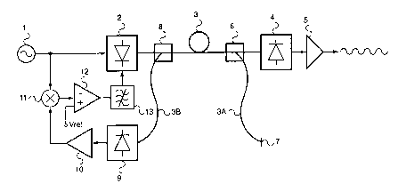
Le signal à commander est envoyé le long d'une fibre optique (3) au moyen d'un laser accordable en longueur d'onde (2) dont la longueur d'onde d'émission peut être variée en fonction d'une variation de phase possible dans le signal reçu par rapport à une phase de référence. € l'extrémité réceptrice de la fibre, un signal de commande est produit par extraction d'une fraction de la puissance associée au signal reçu et le renvoi de cette fraction vers l'extrémité émettrice, où la phase de ladite fraction est comparée avec celle du signal originel et le laser accordable est attaqué (2) pour qu'il transmette sur une longueur d'onde permettant à l'information de base de temps d'atteindre l'extrémité réceptrice avec la phase de référence.


Abrégé anglais


The signal to be controlled is sent along an optical fibre (3) by means of a
wavelength tunable laser (2) whose emission wavelength may be varied as a function
of a possible phase variation in the received signal with respect to a reference phase.
At the receiving end of the fibre a control signal is generated by extracting a fraction of
the power associated with the received signal and sending such fraction back towards
the transmitting end, and at the transmitting end the phase of said fraction is compared
with that of the original signal and the tunable laser is driven (2) in such a way as to
transmit at a wavelength such that the clock information reaches the receiving end with
the reference phase.

Revendications

Note : Les revendications sont présentées dans la langue officielle dans laquelle elles ont été soumises.


CLAIMS
1. Method of controlling the phase of a clock information in a point-to-point
transmission system, wherein said clock information is sent over an optical
transmission line, comprising at least a first optical fibre (3), by means of a
wavelength tunable laser (2) whose emission wavelength can be varied as a
function of a possible variation in the phase of the received information with
respect to a reference phase, and wherein at the receiving end of the system a
control signal is generated by extracting a fraction of the power associated with
the clock information received and sending it back towards the transmitting end
of the system, and at said transmitting end the phase of said fraction is
compared with the phase of the original information and the tunable laser (2) isdriven to make it transmit at a wavelength such that the clock information
reaches the receiving end with the reference phase.
2. Method as claimed in claimed 1, characterised in that the control signal is
transmitted over a second optical fibre (3C) located in very close physical
proximity to the first fibre, in order to be subjected to the same temperature
conditions.
3. Method as claimed in claim 2, characterised in that said first and second optical
fibres (3, 3C) belong to a same optical cable (30) which constitutes the
transmission line of the system.
4. Method as claimed in any of claims 1 to 3, characterised in that said clock
information is represented by a clock signal generated by a generator (1) and
transmitted explicitly.
5. Method as claimed in any of claims 1 to 3, characterised in that said clock
information is represented by the timing of a digital data stream transmitted over
said transmission line and timed by a clock signal generated by a generator (1),and in that a fraction of the power associated with the data stream is utilised as
the control signal and the clock signal is extracted from the control signal at the
transmitting end.
6. Device for controlling the phase of a clock information in a point-to-point
transmission system, wherein a wavelength tunable laser (2), whose emission
wavelength can vary as a function of a possible variation in the phase of the
received information with respect to a reference phase, sends said clock
information on a transmission line comprising at least a first optical fibre (3) and
wherein, at the receiving end of the transmission line (3) there are provided
means (6) for extracting a fraction of the power associated with the received
information and means (7, 6; 6, 3C; 60) for sending such fraction back to the

transmitting end of the line as a control signal, and at said transmitting end there
are provided means (10, 11, 12, 13; 10, 16, 11, 12, 13) for comparing the phase
of the control signal to that of the transmitted clock information and for driving
the tunable laser (2) to make it transmit at a wavelength such that the clock
information reaches the receiving end with the reference phase.
7. Device as claimed in claim 6, characterised in that the means for sending the
control signal towards the transmitting end of the fibre comprise a second optical
fibre (3C), located in close physical proximity to the first one (3), so as to be
subjected to the same temperature conditions.
8. Device as claimed in claim 7, characterised in that the first and second optical
fibres (3, 3C) belong to a same optical cable (30) which constitutes the
transmission line.
9. Device as claimed in any of claims 6 to 8, characterised in that said tunable laser
(2) converts into optical form and sends along the line a clock signal generatedby a generator (1).
10. Device as claimed in any of claims 6 to 8, characterised in that said tunable laser
(2) converts into optical form and sends along the line a digital data stream
emitted by a source (14) and timed by a clock signal generated by a generator
(1), and in that the means (6, 7, 8; 6, 7, 3C; 60) for extracting a fraction of the
power associated with the received information and for sending such fraction
back to the transmitting end of the line are arranged to generate the control
signal starting from a fraction of the power associated with the data stream, and
the phase comparing means also comprise a circuit (16) for extracting the timingfrom the control signal.

Description

Note : Les descriptions sont présentées dans la langue officielle dans laquelle elles ont été soumises.


CA 02220244 1997-11-0~
METHOD OF AND DEVICE FOR CONTROLLING THE PHASE OF A CLOCK SIGNAL
IN A POINT-TO-POINT OPTICAL TRANSMISSION
The present invention relates to synchronisation of communication and
measurement systems and more specifically it concerns a method of and a device for
20 controlling the phase of a clock signal transferred over an optical fibre between two
points of one such system.
In many applications, such as synchronous digital communications,
metrology, etc. there is a need to transmit a highly stable clock signal from one point to
another of the communication network or of the measurement system, e.g. from the25 generator of a main system clock signal to a utilisation point. This signal can be
transferred in many ways, e.g. via radio, by means of microwave links or throughoptical fibres. Clearly the latter way is adopted in digital communication systems which
use optical fibres as physical carriers, e.g. the SDH (Synchronous Digital Hierarchy)
networks. The clock signal can be transmitted explicitly, or it may be implicit in the data
30 stream of a digital transmission and represent the timing of that stream.
For the sake of simplicity, the following description shall, in both cases, refer
to "clock signals" or "clock information".
In the aforesaid applications, clock signals must be highly stable not only in
frequency but also in phase and, considering by way of non limiting example digital
35 communication systems, international standards set strict limits to the phasefluctuations of these signals. If clock signals are transmitted over an optical fibre, the
phase of the signal received by the user is influenced by the variations in the length of

CA 02220244 1997-11-0~
the optical path and it depends essentially on temperature variations along the fibre.
As is well known, such phase is given by ~ = 27~f~, where f is the frequency of the
clock signal to be transferred and ~ is the propagation time along the fibre, in turn
given by ~ = n9Uc, where n9 is the group refractive index (which depends on
S wavelength and temperature) and L is the length of the fibre, which also depends on
temperature. In particular, the dependence of n9 on temperature and wavelength and
the dependence of L on temperature can be expressed by relations:
ng(~, T) = n9~ + (~-~~) a~ + (T - To) aT (1 )
L(T) = Lo + (T - To) aaL (2)
10 where the terms with index "O" indicate the value of the respective parameter at given
reference wavelength and temperature ~o, To.
Since in conventional optical fibre transmission systems wavelength is usually
fixed, it can be clearly seen that the sole parameter influencing the phase is
temperature T.
According to the invention, a method and a device are provided which exploit
the transmission of an optical signal by means of a wavelength tunable transmitter to
obtain an automatic and precise lock of the phase of the received signal to that of the
transmitted signal in a point-to-point optical connection.
In the method, the clock signal is sent along a transmission line, comprising at20 least a first optical fibre, by means of a wavelength tunable laser whose emission
wavelength can be varied as a function of a possible variation in the phase of the
received signal with respect to a reference phase; at the receiving end of the system a
control signal is generated by extracting a fraction of the power associated with the
clock signal received and sending it back towards the transmitting end of the system,
25 and at said transmitting end the phase of said fraction is compared with the phase of
the original signal and the tunable laser is driven in such a way as to transmit at a
wavelength such that the clock signal reaches the receiving end with the reference
phase.
The device comprises: a wavelength tunable laser which sends the clock
30 signal along a transmission line comprising at least a first optical fibre and whose
emission wavelength may vary as a function of a possible variation in the phase of the
received signal with respect to a reference phase; means, located at the receiving end
of the transmission line, for extracting a fraction of the received signal and sending
back that fraction to the transmitting end of the line as a control signal, and means,
35 located at said transmitting end, for comparing the phase of the control signal and that
of the transmitted signal and for driving the tunable laser to make it transmit at a

CA 02220244 1997-11-0~
- 3
wavelength such that the clock signal reaches the receiving end with the reference
phase.
Systems for imposing pre-set delays to optical signals propagating along an
optical fibre, where use is made of wavelength tunable lasers controlled by signals
5 representative of the delay to be imposed, are known from the paper "Continuously
variable true-time-delay modulator", presented by L. Dexter et al. at the OFC/IOOC '93
conference, San José (Ca., USA), 21-26 February 1993, paper ThC6, and from
European patent application EP-A-0 658 994.
For the sake of further clarification, reference is made to the attached
10 drawings, in which:
- Figures 1 and 2 show two embodiments of the apparatus according to the
invention, in the case in which the clock signal is transmitted explicitly;
- Figure 3 shows the apparatus according to the invention in the case in which the
clock signal is implicit in the data stream of a digital transmission;
15 - Figures 4 and 5 show two variants.
With reference to Figure 1, at the transmitting end of a point-to-point
connection a generator 1 of clock signals in electrical form (e.g. a highly stable
oscillator) modulates in amplitude the carrier generated by a wavelength tunable laser
2, which generates an optical signal corresponding to the electrical clock signal. Laser
20 2 sends that optical signal to a receiver 4, by means of an optical fibre 3 which is part,
for instance, of an optical cable constituting the information transmission line. The
clock signal is reconverted into electrical form by receiver 4 and, after being amplified
in an amplifier 5, is then sent to the utilisation devices (not shown). Immediately
upstream of receiver 4 a separation/recombination device 6 (for instance, a fibre
25 coupler, as shown in the drawing, or a partially transparent mirror) is provided, which
extracts a fraction of the optical signal and sends it towards a mirror 7, through a fibre
span 3A. This fraction is reflected by mirror 7 into fibre 3A and is transmitted back
along fibre 3 towards the transmitting end, thereby constituting a control signal. At the
transmitting end, a second separation/recombination device 8, similar to device 6,
30 extracts the control signal and sends it, through a fibre span 3B, towards a second
receiver 9, which reconverts the control signal into electrical form and provides the
converted signal to a second amplifier 10. The control signal thus amplified is
compared in phase to the clock signal emitted by source 1 in a phase comparator
comprising radio frequency mixer 11 and voltage comparator 12. The error signal,35 through a loop filter 13, drives tunable laser 2 to make it emit at a wavelength such that
the signal reaches the receiver with the required phase.
The separation/recombination devices may be made by means

CA 02220244 1997-11-0~
In the variant shown in Figure 2, the output of the separation/ recombination
device 6 conveying the signal fraction used to generate the control signal is connected
to a second optical fibre 3C, distinct from fibre 3, which carries the control signal
directly back to the transmitting end of the system. Fibre 3C shall belong to the same
5 cable 30 as fibre 3 so that, given its physical proximity, its behaviour, from the view
point of temperature effects, is essentially the same as that of fibre 3. Otherwise, the
set up is identical to that of Figure 1, aside from the obvious elimination of separation/
recombination device 8 and mirror 7.
The variant shown in Figure 2 presents the advantage of minimising any
10 multiple reflection phenomena due to the couplers or to the mirrors.
In the embodiment shown in Figure 3, the clock signal emitted by generator 1,
instead of being transmitted directly on fibre 3, is utilised to time a digital data stream
emitted by a data source 14, and the carrier generated by laser 2 is modulated by the
data stream: the clock signal is thus implicit. Amplifier 5 sends the data to the
15 utilisation devices (output 20) and to a first timing extraction circuit 15 which recovers
the clock signal from the data stream and sends it to the utilisation devices (output 21).
A second timing extraction circuit 16, identical to circuit 15, recovers the clock signal
from the control signal and sends it to mixer 12, for comparison with the phase of the
signal generated by generator 1. The remainder of the apparatus is identical to that of
20 Figure 1.
Obviously, in this case too the control signal can be sent back towards the
transmitter by means of a second fibre 3C of cable 30, similarly to what is shown in
Figure 2.
It can immediately be seen that, once the phase of the control signal is locked
25 to that of the transmitted signal, the phase of the received signal also remains
constant. In effect, considering the phase of the signal exiting oscillator 1 equal to 0,
phases F1, F2 of the signal at the receiving end of the connection and of the control
signal, as the latter is received at the transmitting end, shall respectively be 2~f~ and
47cf~. By indicating by ~o the propagation time corresponding to the reference
30 conditions and taking into account relations (1) and (2), propagation time ~ at a
wavelength I and at a temperature T is expressed, as a function of to, lo, To and Lo, by
a relation of the following kind:
~ = ~0 + Lo a (~-~o) + Lo b (T-To)
where a = 1 a 9 and b =--~ a 9 + L aT n9o ~ .

CA 02220244 l997-ll-0~
To obtain the required phase at the receiving end, it will be necessary to
impose that t=to and therefore that
L0-a- (~-~o) + Lo b (T-To)
This condition is obtained by controlling the tunable laser so that it transmits at
5 a wavelength
~= ~0 - (bla)-(T-To)
For a conventional single mode fibre and a transmission in the third window
(around 1550 nm), a _ 17 ps/(nm Km) and b _ 40 ps/~C Km, so that
~ = ~o - 2-2 nm/~C-(T-To)
It is evident that the description above is provided solely by way of non limiting
example, and that variations and modifications are possible without departing from the
scope of the invention. Thus, as shown in Fig. 4, coupler 6 can replaced by a three-
port circulator 80 which has a unidirectional input port connected to the output of laser
2, a bidirectional inpuVoutput port connected to fibre 3 and a unidirectional output port
15 connected to receiver 9; this arrangement has the advantage of eliminating the losses
inherent in the use of an optical coupler. To the same end, mirror 7 in Figs. 1 and 3
can be replaced by a Sagnac interferometer 60, as shown in Fig. 5. Moreover,
although the drawings show the direct modulation of laser 2 by the clock signal emitted
by generator 1 or by the data signal emitted by source 14, the carrier emitted by laser
20 2 could be modulated by means of an external modulator.

Dessin représentatif
Une figure unique qui représente un dessin illustrant l'invention.
États administratifs

2024-08-01 : Dans le cadre de la transition vers les Brevets de nouvelle génération (BNG), la base de données sur les brevets canadiens (BDBC) contient désormais un Historique d'événement plus détaillé, qui reproduit le Journal des événements de notre nouvelle solution interne.

Veuillez noter que les événements débutant par « Inactive : » se réfèrent à des événements qui ne sont plus utilisés dans notre nouvelle solution interne.

Pour une meilleure compréhension de l'état de la demande ou brevet qui figure sur cette page, la rubrique Mise en garde , et les descriptions de Brevet , Historique d'événement , Taxes périodiques et Historique des paiements devraient être consultées.

Historique d'événement

Description Date
Inactive : CIB expirée 2013-01-01
Inactive : Lettre officielle 2007-02-26
Inactive : CIB de MCD 2006-03-12
Le délai pour l'annulation est expiré 2005-11-07
Lettre envoyée 2004-11-05
Lettre envoyée 2001-06-07
Accordé par délivrance 2001-04-03
Inactive : Page couverture publiée 2001-04-02
Préoctroi 2001-01-05
Inactive : Taxe finale reçue 2001-01-05
Un avis d'acceptation est envoyé 2000-07-14
Lettre envoyée 2000-07-14
Inactive : Approuvée aux fins d'acceptation (AFA) 2000-06-27
Lettre envoyée 2000-05-12
Inactive : Transferts multiples 2000-04-11
Demande publiée (accessible au public) 1998-05-07
Inactive : CIB attribuée 1998-02-23
Symbole de classement modifié 1998-02-23
Inactive : CIB en 1re position 1998-02-23
Inactive : CIB attribuée 1998-02-23
Lettre envoyée 1998-01-29
Inactive : Certificat de dépôt - RE (Anglais) 1998-01-29
Demande reçue - nationale ordinaire 1998-01-28
Toutes les exigences pour l'examen - jugée conforme 1997-11-05
Exigences pour une requête d'examen - jugée conforme 1997-11-05

Historique d'abandonnement

Il n'y a pas d'historique d'abandonnement

Taxes périodiques

Le dernier paiement a été reçu le 2000-10-24

Avis : Si le paiement en totalité n'a pas été reçu au plus tard à la date indiquée, une taxe supplémentaire peut être imposée, soit une des taxes suivantes :

  • taxe de rétablissement ;
  • taxe pour paiement en souffrance ; ou
  • taxe additionnelle pour le renversement d'une péremption réputée.

Les taxes sur les brevets sont ajustées au 1er janvier de chaque année. Les montants ci-dessus sont les montants actuels s'ils sont reçus au plus tard le 31 décembre de l'année en cours.
Veuillez vous référer à la page web des taxes sur les brevets de l'OPIC pour voir tous les montants actuels des taxes.

Titulaires au dossier

Les titulaires actuels et antérieures au dossier sont affichés en ordre alphabétique.

Titulaires actuels au dossier
AGILENT TECHNOLOGIES, INC.
Titulaires antérieures au dossier
MARIO PULEO
PIERO GAMBINI
Les propriétaires antérieurs qui ne figurent pas dans la liste des « Propriétaires au dossier » apparaîtront dans d'autres documents au dossier.
Documents

Pour visionner les fichiers sélectionnés, entrer le code reCAPTCHA :


Pour visualiser une image, cliquer sur un lien dans la colonne description du document. Pour télécharger l'image (les images), cliquer l'une ou plusieurs cases à cocher dans la première colonne et ensuite cliquer sur le bouton "Télécharger sélection en format PDF (archive Zip)" ou le bouton "Télécharger sélection (en un fichier PDF fusionné)".

Liste des documents de brevet publiés et non publiés sur la BDBC .

Si vous avez des difficultés à accéder au contenu, veuillez communiquer avec le Centre de services à la clientèle au 1-866-997-1936, ou envoyer un courriel au Centre de service à la clientèle de l'OPIC.


Description du
Document 
Date
(aaaa-mm-jj) 
Nombre de pages   Taille de l'image (Ko) 
Abrégé 1997-11-04 1 20
Description 1997-11-04 5 242
Revendications 1997-11-04 2 99
Dessins 1997-11-04 2 25
Dessin représentatif 2001-02-28 1 5
Dessin représentatif 1998-05-20 1 4
Courtoisie - Certificat d'enregistrement (document(s) connexe(s)) 1998-01-28 1 118
Certificat de dépôt (anglais) 1998-01-28 1 165
Rappel de taxe de maintien due 1999-07-05 1 112
Avis du commissaire - Demande jugée acceptable 2000-07-13 1 162
Avis concernant la taxe de maintien 2005-01-03 1 173
Taxes 1999-10-13 1 28
Taxes 2000-10-23 1 34
Correspondance 2000-05-11 1 23
Correspondance 2001-01-04 1 38
Correspondance 2007-02-25 2 21