Note : Les descriptions sont présentées dans la langue officielle dans laquelle elles ont été soumises.
,CA 02220283 1997-11-OS
WO 96/36036 PCT/LTS96/05431
1 -
VIRTUAL RETINAL DISPLAY WITH
FIBER OPTIC POINT SOURCE
SPECIFICATION
FIELD OF INVENTION
The present invention is directed to a
virtual image display system and more particularly
to a virtual retinal display utilizing an optical
fiber to couple light from a light source to a
scanning system in order to provide a point source
of light at the input of the scanning system.
BACKGROUND OF THE INVENTION
With known virtual image displays, a user
does not view directly a physical display screen
such as with real image displays. Typically, the
virtual display creates only a small physical
image using a liquid crystal array, light emitting
diodes or a miniature cathode ray tube, CRT, the
image being prajected by optical lenses and
mirrors so that the image appears to be a large
picture suspended in the world.
A miniature cathode ray tube can produce a
medium resolution monochrome picture. However,
these devices are heavy and bulky. For example,
a typical weight of a miniature CRT with cables is
greater than four ounces, the CRT having a one
CA 02220283 1997-11-OS -
WO 9G/36036 PCT/US96/05431
- 2 -
inch diameter and a four inch length. Further,
these devices have high voltage acceleration
a
potential, typically 7-13 kilovolts which is
undesirably high for a display that is mounted on -
a user°s head. Creating color using a single
miniature CRT is difficult and usually causes
significant compromises in image resolution and
luminance. Although the CRT image may be relayed -
via a coherent fiber-optics bundle to allow the
CRT to be located away from head mounted optics,
the hardware to accomplish this is also heavy and
causes significant light loss. Field sequential
color using a multiplexed color filter and CRT
with white phosphor is able to create good color
hue saturation but also at a significantly reduced
resolution. For example, three color fields must
be produced during the same period as a normal
60Hz field, thereby dividing the video bandwidth
for each color by three.
A liquid crystal array can produce a color
image using a low operating voltage, but it can
provide only a marginal picture element (pixel)
density, i.e. less than 800 by 800 elements. One
commercial device is known that uses a linear
array of light emitting diodes viewed via a
vibrating mirror and a simple magnifier. Although
this is a low cost and low power alternative, the
display is monochrome and limited in line
resolution to the number of elements which can be
incorporated into the linear array.
Both the CRT and liquid crystal display ,
generate real images which are relayed to the eyes
through an infinity optical system. The simplest
optical system allows a user to view the image
CA 02220283 1997-11-OS
WO 96!36036 PCT1LTS96105431
- 3 -
source through a simple magnifier lens. For
fields of view greater than 30, this approach
leads to a numbers of problems including light loss
and chromatic aberrations. Further, these optics
are bulky and heavy.
Virtual projection optical designs create an
aerial image somewhere in the optical path at an
image plane which is then viewed as an erect
virtual image via an eye piece or objective lens.
This approach increases the flexibility by which
the image from the image source can be folded
around the user's head for a head mounted display
system, but large fields of view require large and
bulky reflective and refractive optical elements.
In addition to resolution limitations,
current systems also have bandwidth deficiencies.
Bandwidth is a measure of how fast the display
system can address, modulate or change the light
emissions of the display elements of the image
source. The bandwidth of the display image source
is computed on the basis of the number of elements
which must be addressed over a given period of
time. Addressing elements temporally is needed to
refresh or maintain a perceived luminance of each
element taking into account the light integration
dynamics of retinal receptors and the rate at
which information is likely to change. The
minimum refresh rate is a function of the light
adaptive state o.f the eye, display luminance, and
pixel persistence, i.e. the length of time the
. picture element produces light after it has been
addressed. Minimum refresh rates of 50 to 60
times a second are typically needed for television
type displays. Further, an update rate of at
CA 02220283 1997-11-OS -
WO 9G/36036 PCT/LTS96/05431
- 4 -
least 30Hz is needed to perceive continuous
movement in a dynamic display or in a presentation
in which the display image is stabilized as a
result of head movement. Refreshing sequentially,
i.e. one element at a time, 40 million picture
elements at a 60hz rate would require a video
bandwidth of 2.4GHz. Bandwidth requirements can
be reduced by interlacing which tricks the eye in
its perception of flicker but still requires that
all of the elements of the image source be
addressed to achieve a minimum update rate of 30Hz
or 1.2GHz bandwidth. Typical television broadcast
quality bandwidths are approximately 8MHz, or two
orders of magnitude less than the 1.2GHz. High
resolution computer terminals have 1400 by 1100
picture elements which are addressed at a 70Hz
non-interlaced rate which is the equivalent to a
bandwidth of approximately 100MHz.
SUMMARY OF THE INVENTION
In accordance with the present invention, the
disadvantages of prior virtual image displays
systems have been overcome. The virtual image
display system of the present invention includes
the use of an optical fiber to provide a point -
source of light that is scanned onto a retina of
a user's eye to create thereon a panoramic, high
resolution, color virtual image. .
More particularly, the virtual image display
system of the present invention includes a source
of light that is modulated with video information.
A scanning system including a horizontal
microscanner and a vertical microscanner scans the
CA 02220283 1997-11-OS
WO 96/36036 PCT/LTS96/05431
- 5 -
video modulated light onto a retina of the user's
eye. A single, monofilament optical fiber has an
entrance aperture into which light from the source
. is directed, the optical fiber coupling the light
to the scanning system in order to provide a point
source of lighi~ at the exit aperture of the
optical fiber.
The source of light utilized with the present
invention may be a laser wherein the optical fiber
provides a point source of light at its exit
aperture without any astigmatism that may be
present in the light emanating from the laser.
The optical fiber also allows the laser and video
modulation circuitry to be positioned remotely
from the scanning system to minimize the weight of
the scanning system when mounted on a user's head.
Alternatively, the source of light utilized
with the system of the present invention may
include a light emitting diode. Known light
emitting diodes have a light emission area that is
typically too large to provide a point source of
light for very high resolution image generation.
The optical fiber, in accordance with the present
invention, receives light at its entrance aperture
from the light emitting diode and provides a point
source of light at its exit aperture.
It is also noted that the source of light
utilized with the system of the present invention
may include multiple light emitters that are
colored, for example a red light emitter, a blue
light emitter and a green light emitter wherein
each light emitter is directly modulatable with
respective red, blue and green video information.
The colored light from each source may be directed
CA 02220283 1997-11-OS -
WO 96/36036 PCT/US96/05431
- 6 -
into an individual optical fiber associated with
the emitter. Alternatively, the colored light
from each of the emitters may be combined and -
thereafter coupled to the entrance aperture of the
optical fiber so as to provide a point source of -
color, video modulated light at the exit aperture
of the fiber. These and other objects, advantages -
and novel features of the present invention as
well as details of an illustrated embodiment
thereof will be more fully understood from the
following description and the drawings.
$RIEF DESCRIPTION OF THE DRAWING -
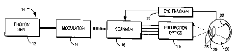
Fig. 1 is a block diagram of the virtual
retinal display of the present invention;
Fig. 2 is a block diagram illustrating one
embodiment of the virtual retinal display depicted
in Fig. 1; -
Fig. 3 is a second embodiment of the virtual
retinal display of Fig. 1 utilizing color;
Fig. 4 is a block diagram illustrating
another embodiment of a color virtual retinal
display in accordance with the present invention;
Fig. 5 is a diagram of an LED array utilized
in a further embodiment of the virtual retinal
display of the present invention employing
parallel photon generation and modulation;
Fig. 6 is an illustration of a laser phased ,
array;
Fig. 7 is an illustration of a microscanner
utilized in accordance with the present invention;
Fig. 8 is an illustration of another
CA 02220283 1997-11-OS
WO 96/36036 PCT/CTS96/05431
_ 7
microscanner that may be utilized in accordance
with the present invention; and
Fig. 9 is a diagram illustrating the optical
system of another embodiment of the virtual
retinal. display of Fig. 1 utilizing an optical
f fiber;
Fig. 10 is a side view of a portion of the
optical fiber depicted in Fig. 9 having an end
directly abutting a LED; and
l0 Fig. i1 is a side view illustrating an
optical fiber having a funnel-like end adjacent to
a photon generator.
DESCRIPTION OF THE PREFERRED EMBODIMENTS
The virtual retinal display 10 of the present
invention as shown in Fig. 1 utilizes photon
generation and manipulation capable of creating a
panoramic, high resolution, color image that is
projected directly onto the eye of a user. The
virtual retinal display does not use a display
that generates a real image such as a CRT, LCD or
LED array as in prior virtual image displays.
Instead, phctons modulated with video information
are scanned directly onto the retina 22 of a
user's eye 20 to produce the perception of an
erect virtual image. Because the virtual retinal
display 10 does not utilize a real image display,
the virtual retinal display 10 is small in size
and weight and is therefore suitable to be easily
mounted on the user's head as a head mounted
display.
More particularly, as shown in Fig. 1,
photons from a photon generator 12 are modulated
CA 02220283 1997-11-OS -
WO 96/36036 PCT/LTS96/05431
8
with video information by a modulator 14. The -
modulated photons are scanned in a f first direction
and in a second direction generally perpendicular
to the first direction by a scanner 16 to create
a raster of photons that is projected directly
onto the retina 22 of the eye 20 of the user by -
projection optics 18 to produce the perception of -
an erect virtual image. Although not necessary,
it is desirable to employ an eye tracking system
24 to reposition the scanned raster of light as
the pupil 26 of the eye 20 moves so that the light -
ray bundles are coincident with the entrance pupil
of the eye. The eye tracking system 24 can also
be used as feedback to change the image or the
focus of the image scanned onto the retina as the
eye moves so that the user perceives that he is
focusing on a different portion of a panoramic -
scene as he shifts his eye. It is noted that the
dotted lines shown entering the eye 20 in Fig. 1
as well as in subsequent figures represents the
range of scanning and not the instantaneous ray
bundle.
The photon generator 12 may generate coherent
light such as a laser or it may generate non-
coherent light such as by utilizing one or more -
LEDs. Further, beams of red, green and yellow or -
blue light may be modulated by RGY or RGB video
signals to scan colored photons directly onto the
user's eye. In order to reduce the bandwidth of ,
the virtual retinal display, multiple -
monochromatic beams or multiple groups of colored , -
beams can be modulated and scanned in parallel
onto the retina where the video information used
to modulate the photons is divided into different
CA 02220283 1997-11-OS
WO 96/36036 PCT/US96/05431
- 9 -
sectors or regions and each beam or group of
0
colored beams is associated with a different
sector of video information as described below.
It is further noted that the functions performed
by one or more of the photon generator 12,
modulator 14, scanner 16 and projection optics 18
can be combined to be performed by fewer elements
depending upon the actual components used in the
system. For example, an acousto-optic deflector
may be used to both modulate the light from the
photon generator 12 and to scan the modulated
light in at least one direction. Further, a laser
phased array may be utilized to perform the
functions of the photon generator, modulator and
one or possibly two scanners as discussed below.
The components of the virtual retinal display
10 can be made small, compact and lightweight so
that the virtual retinal display 10 can easily be
mounted on the head of a user without requiring
a
helmet or an elaborate head mounting for
structural support. Further, the photon generator
12. and modulator 14 can be separated from the
scanner 16 and projection optics 18 so that only
the scanner 16 and optics 18 need be mounted on
the head of a user, the modulated photons being
coupled to the scanner via a bundle of
monofilament optical fibers, or a single
monofilament optical fiber as described in detail
below. In a preferred embodiment, microscanners
are utilized to scan the photons, such
microscanners being small, thin and deflected to
scan the photons in response to an electrical
drive or deflecl=ion signal. Suitable types of
microscanners are described below and in United
CA 02220283 2005-10-11
- 10 -
States Patent No. 5,557,444 assigned to the
assignee of the present invention. The photon
generator, modulator and scanner can therefore be
made very small such as 1~ inch high by 1'~ wide by
5 '~ inch thick or less with a weight of less than an
ounce so as to facilitate a head mounting for the
virtual retinal display 10.
In accordance with one embodiment of the
present invention as shown in Fig. 2, high
10 resolution scanners are used to deflect a beam of
light both horizontally and vertically in a two
dimensional raster pattern. No lens is used to
focus the beam to form a real image in front of the
eye. Instead, the lens 29 of the eye focuses the
15 beam to a point on the back of the retina, the
position of the beam point scanning the retina as
the scanner 16 scans the modulated photons. The
angle of deflection of the collimated light beams
corresponds to the position of the focused spot on
20 the retina for any given eye position just as if an
image Were scanned at an infinite distance away
from the viewer. The intensity of the light is
modulated by the video signal in order to create an
image of desired contrast. Therefore, When the
25 user's eye moves, the user will perceive a
stationary image while he looks at different parts
of the scene. The lateral extent of the image is
proportional to the angle of the scan. Anamorphic
optics are used as necessary to align the scanned
30 photons and to scale the perceived image. By
forming a reduced image of the scanner aperture, a
proportionately larger scanning angle is
CA 02220283 1997-11-OS
WO 9613636 PCT/LTS96105431
- 11 -
yielded. Other than this, the size of the scanner
image is irrelevant as long as the light enters
the eye.
More particularly, as shown in Fig. 2, light
or photons from a photon generator 12 is proj ected
through a cylindrical lens 30 and a spherical lens
32 to an acousto-optical deflector 34 that scans
the photons in a first or horizontal direction.
The cylindrical lens spreads the light beam from
the photon generator 12 horizontally so that it
fills the aperture of the acousto-optical
deflector 34. The spherical lens 32 horizontally
collimates the light which impinges onto the
acousto-optical deflector 34.
The acousto-optical deflector 34 is
responsive to a video signal on a line 36 that is
applied as a drive signal to a transducer of the
acousto-optic deflector 34 to modulate the
intensity of the photons or light from the photon
generator 12 and to scan the modulated light from
the photon generator 12 in a f first direction or
horizontally. The video signal on line 36 is
provided by a video drive system generally
designated 38 that includes a video controller 42.
The video cont~__~oller 42 may include a video
generator such as a frame buffer 40 that provides
video signals on a line 56 and respective
horizontal sync and vertical sync signals. The
video controller 42 may also include a
microprocessor that operates in accordance with
software stored in a ROM 46 or the like and
utilizes a RAM 48 for scratch pad memory. The
horizontal sync signal from the video generator
40
is converted to a ramp wave form by a ramp
CA 02220283 1997-11-OS -
WO 96/36036 PCT/US96/05431 -
12
generator 50, the horizontal sync ramp waveform is -
applied to a voltage controlled oscillator 52 that -
provides a signal in response to the ramp input
having a frequency that varies such that it =
chirps. The output from the voltage controlled
oscillator 52 is applied to an amplifier 54 the -
gain of which is varied by the video data signal -
56 output from the video generator 40 so that the =
video signal 36 output from the amplifier 54 has
an amplitude that varies in accordance with the
video information on line 56 and that has a
frequency that varies in a chirped manner. The
video signal on line 36 is applied to a drive
transducer of the acousto-optical deflector 34.
Varying the amplitude of the drive signal on line
36 with the video information causes the acousto-
optical deflector 34 to modulate the intensity of -
the light from the photon generator 12 with the
video information. Varying the frequency of the
drive signal on line 36 in a chirped manner causes
the acousto-optical deflector to vary the angle at
which the light is deflected thereby so as to scan
the light in a first or horizontal direction.
A spherical lens pair 64 and 68 images the
horizontally scanned light or photons onto a
vertical scanner 62 wherein a cylindrical lens 68 -
spreads the light vertically to fill the aperture
of the vertical scanner 62. The vertical scanner
62 may for example be a galvanometer. The o
vertical sync signal output from the video
generator 40 is converted to a ramp waveform by a
ramp generator 58 and amplified by an amplifier 60
to drive the vertical scanner 62. The speed of
scanning of the vertical scanner 62 is slower than
CA 02220283 1997-11-OS
WO 96136036 PCT/LTS96/05431
- 13 -
the scanning of the horizontal scanner 34 so that
the output of the vertical scanner 62 is a raster
.
of photons. This raster of photons is projected
directly onto the eye 20 of the user by projection
optics taking the form of a toroidal or spherical
optical element 72 such as a refractive lens,
mirror, holographic element, etc.
The toroidal or spherical optical element 72
provides the final imaging and reduction of the
l0 scanned photons. More particularly, the toroidal
or spherical optical element relays the scanned
photons so that. they are coincident near the
entrance pupil 26 of the eye 20. Because a
reduced image of the scanner aperture is formed,
the deflection angles are multiplied in accordance
with the Lagrange invariant wherein the field of
view and image size are inversely proportional.
As the size of the scanned photons, i.e. the exit
aperture of the virtual retinal display are
reduced, the field of view of the image perceived
by the eye increases.
The optical element 72 can be an occluding
element that does not transmit light from outside
of the display system. Alternatively the optical
element 72 can be made light transmissive to allow
the user to view the real world through the
element 72 wherein the user perceives the scanned
virtual image generated .by the display 10
. superimposed on the real world. Further, the
optical element 72 can . be made variably
y transmissive to maintain the contrast between the
outside world and the displayed virtual image. A
passively variable light transmissive element 72
may be formed by sandwiching therein a
CA 02220283 1997-11-OS -
WO 96136036 PCT/US96/05431
- 14 -
photochromic material that is sensitive to light
to change the light transmissiveness of the
element as a function of the ambient light. An -
actively variable light transmissive element 72
may include a liquid crystal material. A
photosensor can be used with such an element to
detect the amount of ambient light wherein a bias -
voltage across the liquid crystal material is
varied in accordance with the detected light to
actively vary the light transmissiveness of the
element 72.
The system described thus far with respect to
Fig. 2 is monocular. In order to provide a
stereoscopic system a second virtual retinal
display 10' may be utilized in parallel with the
first retinal display 10, the second virtual
retinal display lo' projecting scanned photons
modulated with the appropriate video information
directly on the second eye 20' of the user. This
provides a medium for binocular depth information
so that displayed objects appear at different
depths. Each pixel of the object, however,
appears at the same distance from the user which
can create a possible conflict between the
stereoscopic cue and the monocular cue where the
stereoscopic cue deals with the positioning of the
object with respect to each eye and the monocular
cue deals with the focus of the light of the
object being imaged on the retina. More
particularly, in prior virtual image display
systems, each monocular image plane was typically
focused at optical infinity causing each of the
pixels within the virtual image to appear at one
distance. However, the combination of two prior
CA 02220283 1997-11-OS
WO 96136036 PCT/US96105431
- 15 -
monocular systems to form the binocular view
a
created a possible conflict between the distance
cues and the focus or accommodation cue.
The virtual retinal display of the present
, invention overcomes this problem by utilizing
an
accommodation cue 70 either in the monocular
display system 10 or in the binocular display
system formed of displays 10 and 10~. The
accommodation cue 70 is a focusing 'or depth cue
that is controlled to vary the focus or
convergence or divergence of the scanned photons
rapidly to control the depth perceived for each
picture element of the virtual image. Therefore
in accordance with the present invention true
depth perception is obtained by modulating each
pixel for depth individually such as by
controlling the focus, i.e. the convergence or
divergence, of the individual pixel. The
accommodation cue 70 includes a reflective surface
that changes shape rapidly. For example, a
miniature mirror having a deformable membrane
whose shape is altered as the membrane is charged
and discharged may be .used to form the
accommodation cue. The deformation of the
membrane is thus varied by an electrical drive
signal to control the convergence or divergence
of
each pixel for depth. The drive of the
accommodation cue 70 is provided by the video
controller 42 which may, for example, store a Z
axis video information buffer in the memory 48 or
in the video generator 40 in addition to the two
dimensional video information in a typical frame
buffer.
CA 02220283 1997-11-OS
WO 96/36036 PCT/US96105431 =
- 16 -
A further embodiment of the virtual retinal -
display 10 of the present invention is depicted in
Fig. 3 for scanning colored photons directly onto
the retina of a user's eye. As shown in Fig. 3,
the photon generator 12 includes colored lasers or
LEDs such as a red photon generator 80, a green -
photon generator 82 and a blue photon generator -
84. If a blue photon generator is unavailable, a
yellow photon generator may be utilized. The
l0 colored photons from the generators 80, 82 and 84 -
are modulated with respective RGB video -
information from the video generator 40 and then -
combined by a beam combiner/dispersion
precompensator 86. The output of the beam
combiner/dispersion precompensator 86 is projected
onto the horizontal scanner 34 by the cylindrical
lens 30 and the spherical lens 32. It is noted
that the horizontal scanner may be other than the -
acousto-optic scanner shown in Fig. 2. For
example, a resonant mechanical scanner or various -
types of microscanners as discussed below may be
used for the horizontal scanner. The horizontally
scanned color modulated photons output from the
scanner 34 are projected onto a dispersion -
compensator 88 the output of which is projected
onto a prism before being projected onto the
vertical scanner 62 by the spherical lens pair 64
and 68.
The colored photon raster as scanned from the .
output of the vertical scanner 62 is projected by
a spherical lens 92 onto an offset mirror 96 which . -
is moved by the eye tracker 106 so as to position
the raster of photons directly onto the entrance -
pupil 26 of the eye 20 as the pupil moves. In one _
CA 02220283 1997-11-OS
W O 96?36036 PCT/1JS96/05431
- 17 -
embodiment, a beam splitter 100 directs an image
a
reflected off of the cornea of the eye 20 to a
lens 102 and a position sensing diode 104 that is
coupled to the eye tracker 106 to detect the
position of the pupil 26. In response to the
detected position of the pupil, the eye tracker
correctly positions the offset mirrors) 96 so
that the exit pupil or aperture of the virtual
retinal display is approximately aligned with the
entrance pupil of the eye and/or to adjust the
scan angle to reflect changed video information as
described below.
The instantaneous position of the pupil 26 as
determined by the eye tracker 106 is also
communicated to the video controller 42 so that
the microprocessor 44 can direct video information
to modulate the colored light where the video
information reflects a change in the direction of
the user's view. More particularly, the detected
pupil position is used by the microprocessor 44 to
position a "visible window' on the video
information stored in the frame buffer 40. The
frame buffer 40 may for example store video
information representing a panoramic view and the
position of the visible window determines which
part .of the view the user is to perceive, the
video information falling within the visible
window being used to modulate the light from the
photon generator 12.
It is noted that, because the acousto-optical
deflector 34 'diffracts red light more than green
light and diffracts green light more than blue
light, this variation in the diffraction must be
compensated for. In accordance with the present
CA 02220283 1997-11-OS
WO 96/36036 PCT/US96/05431
- 18 -
invention, this variation in diffraction may be -
compensated for by appropriately delaying via
delays 108, 110 and 112 the RGB video signals that
are coupled~to the respective red, green and blue
photon generators 80, 82 and 84 to modulate the
red, green and blue photons with the appropriate
red, green and blue video information.
In another embodiment of the virtual retinal
display of the present invention as shown in Fig.
4, composite video or RGB video signals are
received by a digital video scan converter 120 and
separated into multiple compartments that
represent sectors or regions of an image to be
scanned. Multiple video drive signals output from
the video amplifiers 124 representing each sector -
are used to modulate the light from the photon -
generator 12 in parallel. The photon generator -
may consist of either arrays of lasing diodes or
arrays of high luminance light emitting diodes. -
Multiple beams of red, green and yellow or blue
light are modulated with the video signals in
parallel for each of the divided sectors or -
regions and then relayed directly or by
monofilament optical fibers 131 to a microscanner
16. The microscanner 16 essentially performs two -
functions. First, the microscanner scans the
multiple color beams associated with each sector
or region in two axes to create a raster of light
on the retina and not an aerial image, there being _
no.image plane between the photon generator 12 and
the eye 20. Second, the microscanner 16 functions =
to position the scanned light relative to the
instantaneous entrance pupil 26 of the eye as
sensed by the eye tracker.24.
CA 02220283 1997-11-OS
WO 96/36036 PCT/LTS96/05431
19 -
More particularly, the scanner 16 includes a
first microscanner 132 that is responsive to an
X
axis deflection signal output from a deflection
amplifier 136 to scan the color beams in a
horizontal direction where the amplifier 136 is
driven by the harizontal sync signal from a scan
generator 122. A second microscanner 134 is
responsive to a Y deflection signal from the
deflection amplifiers 136 as driven by the
vertical sync or deflection drive from the scan
generator 122 to scan the horizontally scanned
color photons in the vertical direction. A scan
collimation lens 140 receives a two dimensionally
modulated light field that is projected onto a
tri-color combines 142. The combines 142 in turn
projects the scanned light onto a Maxwellian-view
optical system 148. The optical system 148
projects the scanned colored photons onto a raster
position deflect-or which may include two axis
galvo mirrors that in turn project the scanned
light onto a toroidal optical element such as a
combines 152 having a trichoric coating, the
toroidal combines 152 projecting the scanned color
photons directly onto the eye 20.
For eye tracking, the eye tracker 24 includes
an infrared light source which illuminates the
surface of the eye with low intensity infrared
light either directly or indirectly as shown. The
surface of the eye is viewed through the raster
position deflector 150 via the combines 142, a
lens 140 and a charge coupled device, CCD, array
146. The signals from the CCD sensor 146 are
processed by a pupil position processor 154 to
generate null signals, DH and ~V, that are coupled
CA 02220283 1997-11-OS -
WO 96/36036 PCT/CTS96/05431 -
to respective color deflection amplifiers 158 and
to the raster positioning mirrors 150 so as to -
cause the scanned photons to follow the pupil of -
the user's eye 20.
5 An example of a light emitting diode array
suitable for use in the present invention is -
illustrated in Fig. 5. If an X-Y visual field is
considered to be composed of an array of 2,000 x
2,000 resolvable spots or pixels, the spots must
10 be refreshed 50 times per second so as to have an -
information bandwidth of approximately 200MHz.
High brightness LEDs typically have a power
bandwidth curve that starts to roll off above
2MHz. This result is essentially an R-C product -
15 limitation related to the diffusion capacitance of
a heavily forward-biased p-n junction. In order
to meet the bandwidth requirements of the system,
a linear array of 50 to 100 LED pixels per color
are utilized. Using a red, green and blue LED
20 scheme would require 50-100 LEDs of each of these -
three colors. As shown in Fig. 5, an array 200
includes LED chips 201, 202, 203 - N wherein each -
LED chip includes an LED active area 205. The LED
active area may include a GaAsP alloys and a Si3 N4
dielectric overlayer.
A laser phased array as illustrated in Fig.
6 functions to perform photon generation, video
modulation and scanning in at least one direction.
The laser phased array includes a thin film wave
guide 210, phase modulator electrodes 212, a
cleaned coupled cavity 214 and laser cavities 216,
the array emitting a coherent beam of about lOmW
power. When two closely spaced lasers are
fabricated in the same chip of material, their
CA 02220283 1997-11-OS
W O 96136036 PCT/US96/05431
- 21 -
optical fields become coupled so that the
processes of optical emission in the two devices
d
are correlated and coherent. The result is a well
defined phase front emitted from the laser pair.
In the laser phased array 220 having a number of
laser cavities 216, the optical beam is phase
coherent if the lasers are spaced within 10
microns of each other. This resolution can be
achieved by photolithographic techniques. The
to electro-optic modulator works by modifying the
index of refraction of the wave guide medium 210
through which the optical beam must travel before
being launched into free space. By separating the
electrical contacts 212 for each modulator, the
relative phase of each individual laser in the
array can be modified by the modulator. For an
appropriate series of modulation voltages, the
phase front of the laser array coupled beam can
be
modified so that the emitted beam is launched at
an angle to the normal exit direction. With the
appropriate series of modulation voltages the
laser beam can be scanned in a given direction.
It is possible to construct a two axis laser
phased arra~ so that an additional scanner is not
needed to scan the laser in a perpendicular
direction.
An example of a microscanner 132, 134 for
scanning photons is illustrated in Fig. 7. The
microscanner includes an actuator 230. The
actuator 230 is a piezoelectric bimorph cantilever
that is capable of three dimensional motion in
response to an electrical drive signal. By
controlling the deflection of the cantilevered
actuator with the appropriate drive signals, the
CA 02220283 1997-11-OS -
WO 96/36036 PCT/US96/05431
- 22 - -
actuator 230 deflects the photons incident thereto
to scan the photons.
Another example of a microscanner that can be
made extremely small is shown in Fig. 8, the
microscanner having a curved reflective surface
that translates to scan light impinging thereon in -
one direction. More particularly, the
microscanner 240 includes a base.or actuator 242
formed of a piezoelectric material with a
substrate 244 formed on the actuator 242 wherein
the substrate 244 has a curved reflective surface
246. In response to a varying drive signal the
piezoelectric actuator and the substrate 244
translate in the direction of the arrows 248 so as -
to scan the light impinging on the surface 246 of -
the substrate in a first direction generally
perpendicular to the direction 248 of translation.
A second microscanner 250 scans the light
impinging thereon in a second direction
perpendicular to the first direction so as to scan
a raster image directly onto the retina of a
user°s eye.
In still another embodiment of the present
invention as depicted in Fig. 9, one single mode,
monofilament optical fiber 300 or single strand
optical fiber is utilized to couple light from a
light source such as the photon generator 12 to
the scanning system 16. The single monofilament _
optical fiber 300 includes an entrance aperture .
302 leading into the single core 304 of the fiber
300, the core 304 extending the length of the ,
optical fiber to an exit aperture 306. The exit
aperture 306 of the single monofilament optical -
fiber 300 may be extremely small. For example the -
CA 02220283 1997-11-OS
WO 96/36036 PCT/US96/05431
- 23 -
diameter of the exit aperture may be l0 microns or
less and preferably on the order of 3.5 microns so
,,
as to provide a point source of light for input to
the scanning system 16.
The photon generator 12, as described above,
may generate coherent light such as a laser. In
a laser embodiment of the system depicted in Fig:
9, the optical fiber 300 allows the laser source
as well as the video source and video modulation
portion of the system to be located remotely from
the scanning system 16. The optical fiber 300 has
a further advantage when the laser source is a
laser diode or other laser generator that produces
astigmatic light. More particularly, laser diodes
typically generate astigmatic light which, when
scanned onto the retina of a user's eye will not
produce a round pixel as desired but a distorted
pixel such as an elliptical pixel. The optical
fiber 300 when used with such a laser source will
convert the astigmatic laser light into a circular
point source at the exit aperture 306 of the fiber
300 so as to obtain circular or round pixels when
the light is scanned onto the retina.
The photon generator 12 as shown in Fig. 9
may also include a light emitting diode (LED).
LEDs do not generate coherent light. Further, the
light emission area of an LED is typically too
large for very high resolution image generation as
is required for certain applications of the
display system. Although optics, such as lenses,
can be used to shrink the apparent size of an LED
light source, use of such optics can result in a
loss of intensity and further, an increase in the
optical path length so as to increase the overall
CA 02220283 1997-11-OS
WO 96/36036 PCT/CTS96/05431
24
size of the display system. However, when the LED -
light is coupled to a single mode, monofilament
optical fiber 300, the exit aperture 306 of the
fiber 300 will form a point source of light that
is small enough for very high resolution image -
generation. It is noted that a typical LED might
have a light emission area 308 that is on the
order of 500 microns. In accordance with the
present invention, the optical fiber 300 allows
the very large light emission area of the LED to
be reduced to less than 10 microns and preferably
on the order of 3.5 microns for a fiber 300 having
a core 304 diameter on that order.
A lens such as the lens 310 shown in Fig. 9
may be used to focus the light from a laser, a LED
or other type of photon generator 12 into the
entrance aperture 302 of the optical fiber 300.
Alternatively, as shown in Fig. 10, the end 312 of -
the optical fiber containing the entrance aperture -
302 may abut directly against the photon generator
12 which is shown as an LED 314. As seen in Fig.
10, the diameter or area of the entrance aperture
302 of the optical fiber is much smaller than the
light emission area 308 of the LED 314. Fig. 11
depicts a further embodiment for coupling the -
light from the photon generator 12 to the optical
fiber 300. In this embodiment, the optical fiber
300 is formed with a funnel-like end portion 316
leading into entrance aperture 302 of the small, ,
constant diameter core 304 of the optical fiber
300 with an entrance aperture 302. An entrance , -
aperture 318 of the fiber's funnel portion 316 has
a diameter that is greater than the diameter of
the entrance aperture 302 of the constant diameter -
CA 02220283 1997-11-OS
WO 9G/3603G PCT/US96/05431
- 25 -
core portion 320 of the optical fiber 300. The
funnel end portion 316 of the optical fiber shown
in Fig. 11 may directly abut the photon source 12
or, alternatively, it may be positioned merely in
close proximity thereto.
. The light from the point source formed at the
exit aperture 306 of the optical fiber 300 is
coupled to a horizontal microscanner 332 of the
scanning system 16 via a lens 330. The light
incident to the horizontal microscanner 332 is
directed onto a vertical microscanner 334 and
scanned onto the retina of a user's eye via a lens
336. The distance between the exit aperture 306
of the optical fiber 300 and the lens 330 may be
adjusted so that the light output from the lens
330 converges to form an image plane 340 between
the output of 'the scanning system 16 and the
user's eye. The lens 336 is a collimating lens
that directs the light onto the user's retina. In
order to adjust the field of view of the virtual
retinal display depicted in Fig. 9, the lens 330
and the lens 336 may be moved closer together or
farther apart. Because the system of the present
invention is very compact including only minimal
optical elements, the lenses 330 and 336 may be
ganged together in a manner so that the lenses can
be moved together, inwardly towards each other or
outwardly away from each other so that the user
does not have to make separate adjustments
thereto. This can be accomplished by utilizing a
zoom lens mounting structure of the like for the
lenses 330 and 336.
It is further noted, that the source of light
input to the entrance aperture 302 of the optical
CA 02220283 1997-11-OS
WO 9G/3603G PCT/US96/05431
- 26 -
fiber 300 may include a red light emitter, a blue -
light emitter and a green light emitter to provide
a full color system. Preferably, each of these
light emitters is directly modulatable with video
information. However, separate video modulators -
.may also be utilized with the colored light -
emitters to modulate the red light with red video
information, the blue light with blue information -
and the green light with green video information.
The light from each of the colored emitters may be -
directed into an optical fiber associated with -
that individual light emitter, each of the optical
fibers being coupled to a single optical fiber 300 -
so.as to provide at the exit aperture 306 thereof
a point source of color, video modulated light.
Alternatively, the colored light from each of the
emitters may be combined as described above prior =
to being input to the entrance aperture 302 of the
optical fiber 300.
Many modifications and variations of the =
present invention are possible in light of the
above teachings. Thus, it is to be understood -
that, within the scope of the appended claims, the -
invention may be practiced otherwise than as -
described hereinabove. -
What is claimed is: -