Note : Les descriptions sont présentées dans la langue officielle dans laquelle elles ont été soumises.
CA 02220371 1997-11-06
TITLE: APPARATUS AND METHOD FOR GENERATING
ULTIMATE SURFACES ON OPHTHALMIC LENSES
FIELD OF THE INVENTION
The present invention relates to an apparatus for generating a final
surface on an ophth~lmic lens in a single operation. The present invention
also relates to a method for operating an ophth~lmic lens generating
apparatus wherein the movement of the surface generating tool along the
5 axis of lens is a mechanically-advantaged movement.
BACKGROUND OF THE INVENTION
A first type of general ophth~lmic lens generating apparatus has a
cup-shaped abrading tool repeatedly sweeping across the surface of a lens
10 blank until the prescribed curvature is obtained. The cup-shaped abrading
tool is affixed to a slide plate movably mounted on a swing arm. The
center of rotation of the swing arm is movable towards and away from a
lens blank holder and the length of the swing arm is adjustable. The slide
plate is movable about a pivot which is coaxial with the center of radius of
15 the edge of the abrading cup. The base curve on the ophth~lmic lens is
determined by the length of the swing arm, and the cross curve is
determined by the angular relationship of the abrading tool relative to the
axis of the lens blank.
Various inventions pel Lai~ g to ophth~lmic lens generating
20 apparatus of the first type are illustrated and described in the following
U.S. Patents:
CA 02220371 1997-11-06
U.S. Patent 3,458,956 issued on August 5, 1969 to J.M. Suddarth et al;
U.S. Patent 4,068,413 issued on January 17, 1978 to J.M. Suddarth;
U.S. Patent 4,419,846 issued on Dec. 13, 1983 to G. Schimit7ek et al;
U.S. Patent 4,574,527 issued on March 11, 1986 to R.S. Craxton;
U.S. Patent 4,653,233 issued on March 31, 1987 to E. Brueck;
U.S. Patent 4,866,884 issued on Sept. 19, 1989 to K.L. Smith et al;
U.S. Patent 5,181,345 issued on January 26, 1993 to S. Kulan.
A second type of ophth~lmic lens generating apparatus of the prior
lo art is characterized by the use of a co~ uler and linear servo-actuators formoving the tool or the lens holder during the lens generating process. The
prescribed curvature on the ophth~lmic lens is obtained by interpolating
and simultaneously guiding the motions of the linear actuators.
Examples of colllpuler-controlled lens generating apparatus of the
prior art are provided in the following U.S. Patents:
U.S. Patent 4,493,168 issued on January 15, 1985 to E.L. Field, Jr.;
U.S. Patent 4,908,997 issued on March 20, 1990 to E.L. Field, Jr. et al;
U.S. Patent 5,485,771 issued on January 23, 1996 to Brennan et al.
In the lens generating apparatus of the first type, the advance of the
abrading tool towards the surface of the lens is directly related to the
extension of the swing arm or to the height of the arc defined by the
sweeping of the tool against the surface of the lens blank. Similarly, in the
computer-controlled lens generating apparatus, the precision of a
displacement of the abrading tool in a direction generally perpendicular to
a plane defined by a lens blank is directly related to a smallest increment
of the linear actuator moving the tool in this direction. Therefore, any
defect in the mech~ni.~m for articulating or extending the swing arm in the
CA 02220371 1997-11-06
al~pal~lus of the first type as well as any defect in the linear actuators of a
co~ u~er-controlled apparatus has a direct effect on the quality of the
surface being generated by these machines.
Although ultra-smooth mech~nisms and servo-actuators are
5 available commercially, the level of precision required by the optical
industry generally exceeds the most stringent precision requirement by
industrial sectors. Consequently, it has been generally accepted that an
ophth~lmic lens generated on the apparatus of the prior art requires
extensive fining and polishing of the surface of the lens for correcting focal
10 errors in the generated lens and for obtaining a proper transparency of the
lens' surface.
SUMMARY OF THE INVENTION
In the present invention, however, there is provided a lens
generating apparatus wherein the precision thereof is enhanced by
15 compounding the movements of a rotary actuator and one or more linear
actuators for greatly increasing the displacements of the linear actuators
relative to the actual movement of the lens surfacing tool.
In a first aspect of the present invention, the apparatus comprises a
base having orthogonal horizontal longitudinal axis, horizontal transversal
20 axis and a vertical axis, a tool spindle having a motor and a lens surfacing
tool mounted on a rotatable arbor of the motor for rotation by the motor,
and a lens holder having a chuck for retaining an ophth~lmic lens with a
perimeter thereof ~çfining a plane being substantially perpendicular to the
horizontal longihl~in~l axis. The apparatus of the present invention also
25 comprises a first linear slide means affixed to the base and having a first
movable support and a first linear actuator connected to the first movable
CA 02220371 1997-11-06
support for moving the first movable support along the horizontal
longit~l-lin~l axis. There is also provided a rotary table affixed to the first
movable support and supporting the tool spindle. The rotary table has a
rotary actuator connected thereto for rotating the tool spindle about the
5 vertical axis. The a~ lus of the present invention further has a computer
having means for ~imlllt~neously controlling displacements of the first and
rotary actuators.
The lens surfacing tool of the apparatus of the present invention has
a working circumference and a plurality of cutters affixed to the working
10 circumference. The working circumference has a cutting side for
contacting the surface of the ophth~lmic lens. The tool spindle is mounted
on the rotary table with the cutting side of the lens surfacing tool being
disposed at a nominal radius from the vertical axis.
A primary advantage of the a~ us of the present invention is that
15 when the lens holder is positioned aside the horizontal longitudinal axis
and the first and rotary actuators are operated simultaneously for moving
the cutting side of the lens surfacing tool across a surface of the ophth~lmic
lens, along a prescribed base curve for the ophth~lmic lens, a total
displacement of the first movable support along the longitudinal axis is
20 greater than the depth of the base curve in the ophth~lmic lens. Therefore,
an actual output increment of the lens surfacing tool along the horizontal
longihl~lin~l axis is smaller than a rated input increment of the first linear
actuator. Actually, when the ophtll~lmic lens is a circular lens having a
diameter of about 70 mm and the nominal radius between the cutting side
25 of the tool and the vertical axis is about 205 mm, the total displacement of
the first movable support along the horizontal longitudinal axis is about
between 50 and 80 times larger than the depth of the base curve in the
ophth~lmic lens.
CA 02220371 1997-11-06
In another aspect of the present invention, the lens generating
apparatus also has a second linear slide affixed to the base and having a
second movable support supporting the lens holder, and a second linear
actuator connected to the second movable support for moving the second
5 movable support and the lens holder along the horizontal transversal axis.
In some instances the second linear actuator may also be operated
simultaneously with the rotary and first linear actuators for reducing the
displacement of the cutting side of the lens surfacing tool relative to the
surface of the lens along the horizontal transversal axis. As will be
10 explained later, when the second linear actuator is operated, the sum of the
displacement of the cutting side of the lens surfacing tool along the
horizontal transversal axis plus the displacement of the ophth~lmic lens
along this transversal axis is about between 1.0 and 4.0 times more than the
width of the ophth~lmic lens.
In a further aspect of the present invention, there is provided a novel
method for operating the apparatus of the present invention wherein the
precision thereof is enhanced. This method comprises the steps of:
a) moving the lens holder near a far end of the second linear slide with
the ophth~lmic lens being positioned on one side of the horizontal
longihl~in~l axis and having a far edge and a near edge relative to
the horizontal longitudinal axis,
b) rotating the rotary table such that the rotatable arbor of the tool
spindle is oriented in a vicinity of a parallel alignment with the
horizontal transversal axis,
25 c) moving the first movable support such that the cutting side of the
lens surfacing tool is near one of the far and near edges of the
ophth~lmic lens;
CA 02220371 1997-11-06
d) rotating the lens surfacing tool and moving the first movable support
for moving the cutting side of the lens surfacing tool in contact with
the ophth~lmic lens;
e) simlllt~neously rotating the rotary table and actuating the first linear
actuator for sweeping the cutting side of the lens surfacing tool
along a prescribed base curve across the optical surface of the
ophth~lmic lens.
An advantage of the novel method of the present invention is that
when the rotatable arbor of the tool spindle is oriented in the vicinity of a
I o parallel alignment with the horizontal transversal axis, a displacement of
the first movable support for partly subtracting a component of an arcuated
displacement of the lens surfacing tool about the vertical axis, along the
horizontal longitudinal axis, for m~int~ining the cutting side of the lens
surfacing tool within the prescribed base curve, is much larger than an
actual depth of the prescribed base curve in the ophth~lmic lens. A
precision in the movement of the lens surfacing tool is thereby greatly
enhanced.
BRIEF DESCRIPTION OF THE DRAWINGS
The preferred embodiment of the present invention will be further
understood from the following description, with reference to the drawings
in which:
- Figure 1 is a schematic plan view of a first type of toric surface
generator of the prior art;
- Figure 2 is a schematic plan view of a second type of toric surface
generator of the prior art;
CA 02220371 1997-11-06
- Figure 3 is a schematic plan view of a third type of toric surface
generator of the prior art;
- Figure 4 is a front, right side and top perspective view of the
ophth~lmic lens generating apparatus of the preferred embodiment;
5 - Figure 5 is a top plan view of the ophth~lmic lens generating
apparatus of the preferred embodiment;
- Figure 6 is a front elevation view of the ophth~lmic lens generating
apparatus of the preferred embodiment;
- Figure 7 is a front, driven side and top perspective view of a typical
surface generating tool used on the ophth~lmic lens generating
~pal~lus of the preferred embodiment;
- Figure 8A is a schem~tic plan view of the apparatus of the preferred
embodiment showing the position of the tool spindle at the
beginning of a cut relative to the lens blank, in a first example of a
lens generating process;
- Figure 8B is a schem~tic plan view of the appalaLus of the preferred
embodiment showing the position of the tool spindle at the end of
a cut relative to the lens blank in the first example of a lens
generahng process;
20 - Figure 8C is a superimposed illustration of the positions of the tool
spindle and of the lens blank at the start and at the end of the cut of
the first example of a lens generating process,
CA 02220371 1997-11-06
- Figure 8D illustrates for reference purposes the diameter of the lens
blank, and the depth of cut corresponding to the dioper value of the
base curve in the lens generating process of the first example;
- Figure 9A is a sçhem~tic plan view of the a~lus of the preferred
embodiment showing the position of the tool spindle at the
beginning of a cut relative to the lens blank, in a second example of
a lens generating process,
- Figure 9B is a schem~tic plan view of the apparatus of the preferled
embodiment showing the position of the tool spindle at the end of
a cut relative to the lens blank in the second example of a lens
generating process;
- Figure 9C is a superimposed illustration of the positions of the tool
spindle and of the lens blank at the start and at the end of the cut of
the second example of a lens generating process;
15 - Figure 9D illustrates for reference purposes the diameter of the lens
blank, and the depth of cut corresponding to the dioper value of the
base curve in the lens generating process of the second example;
- Figure lOA is a schematic plan view of the apparatus of the
pl~;relled embodiment showing the position of the tool spindle at the
beginning of a cut relative to the lens blank, in a third example of a
lens generating process;
CA 02220371 1997-11-06
- Figure lOB is a schematic plan view of the apparatus of the
pre~lled embodiment showing the position of the tool spindle at the
end of a cut relative to the lens blank in the third example of a lens
generating process;
5 - Figure lOC is a superimposed illustration of the positions of the
tool spindle and of the lens blarlk at the start and at the end of the
cut of the third example of a lens generating process;
- Figure lOD illustrates for reference purposes the diameter of the
lens blank, and the depth of cut corresponding to the dioper value
of the base curve in the lens generating process of the third
example;
- Figure llA is a schematic plan view of the apparatus of the
pre~ d embodiment showing the position of the tool spindle at the
beginning of a cut relative to the lens blank, in a fourth example of
a lens generating process;
- Figure llB is a schematic plan view of the apparatus of the
pler~lled embodiment showing the position of the tool spindle at the
end of a cut relative to the lens blank in the fourth example of a lens
generating process;
20 - Figure llC is a superimposed illustration of the positions of the
tool spindle and of the lens blank at the start and at the end of the
cut of the fourth example of a lens generating process;
CA 02220371 1997-11-06
- Figure llD illustrates for reference purposes the diameter of the
lens blank, and the depth of cut corresponding to the dioper value
of the base curve in the lens generating process of the fourth
example;
5 - Figure 12A is a schematic plan view of the apparatus of the
plerelled embodiment showing the position ofthe tool spindle at the
beginning of a cut relative to the lens blank, in a fifth example of a
lens generating process;
- Figure 12B is a schematic plan view of the apparatus of the
pl~ d embodiment showing the position of the tool spindle at the
end of a cut relative to the lens blank in the fifth example of a lens
generating process;
- Figure 12C is a superimposed illustration of the positions of the
tool spindle and of the lens blank at the start and at the end of the
cut of the fifth example of a lens generating process;
- Figure 12D illustrates for reference purposes the diameter of the
lens blank, and the depth of cut corresponding to the dioper value
of the base curve in the lens generating process of the fifth example.
DETAILED DESCRIPTION OF THE PREFERRED EMBODIMENT
The preamble to this section provides an overview of the operation
of ophth~lmic lens surfacing equipment of the prior art. This overview is
presented here to refresh the reader's memory of these toric surface
generators and to better describe a common drawback of these machines.
CA 02220371 1997-11-06
Typical toric surface generators ofthe prior art, and especially those which
are controlled by con,puler are illustrated in Figures 1, 2 and 3.
The toric surface generator 20 which is partly illustrated in Figure
1, has a cup-shaped cutter wheel 22 which is adjustably mounted on a
headstock 24. The machine also has a lens holder 26 mounted on a
tailstock 28. The cutter wheel 22 is swept across the longitudinal axis 30
of the tailstock about pivot 'A' for example, for shaping the surface of the
lens blank 32. Pivot 'B' and the cutter wheel 22 are movable along the axis
34 of the headstock 24. The position of the lens blank 32 is also adjustable
lo along the longitudinal axis 30 of the tailstock. During each cut, the
inclination of the cutter wheel 22 about pivot 'B', and its position relative
to the lens blank 32, and the position of the lens blank 32 along the axis 30,
may be contin~ y changed.
The movements of both the he~dstock 24 and tailstock 28 are driven
by a respective stepper motor and lead screw (not shown). A computer
controller is used to operate the stepper motors for cutting both convex and
concave toric lenses.
In the example of Figure 2, the lens grinding apparatus 40
illustrated therein has a cup-shaped cutter tool 42 which is mounted on a
cross slide 44. The cross slide 44 is mounted on a base slide 46 and is
adjustable relative to the base slide 46 about pivot 'C', for controlling the
head angle of the tool 42. A sweep platform 48 is connected to the base
slide 46 and is rotatable about pivot 'D'. The position of the base slide 46
relative to the sweep platform 48 is adjustable for ch~ngin~ the radius of
the prescribed base curvature on the lens.
11
CA 02220371 1997-11-06
The lens blank 50 is mountable on a tailstock 52 which is also
movable along the longi~l-lin~l axis 54 of the a~pal~lus. The extension and
retraction of the base slide 46 and the rotation of the cross slide 44 and the
sweep platform 48 are controlled by a microprocessor and servo-
5 mech~ni.cm~
In the third example of toric surface generators of the prior art,Figure 3 illustrates a co~ uler-controlled lens generator 60 having a cup-
shaped tool 62 which is adjustably mounted on a t-lrning base 64. A lens
blank 66 is mountable in a lens holder 68. The lens holder 68 is mounted
10 on a X-Y table comprising linear ball bushing bearings (not shown), two
pairs of round ways 70, a X-axis linear actuator 72 and a Y-axis linear
actuator 74. The tllrning base 64 and X-Y table are simultaneously
operable for controlling the relative movement of the lens blank 66 and the
tool 62 for obtaining the prescribed lens curvatures.
In the light of the above review of the col~ uler-controlled
ophtll~lmic lens generating apparatus of the prior art, it will be appreciated
that the precision of the cross curve on a generated lens is defined primarily
by the shape and inclination of the cup-shaped tool relative to the lens
surface. In that respect, it will also be appreciated that the diameter of the
20 tool is a fixed value and the inclination of the tool is effected generally by
mech~ni.cm.~ having significant leverage or mechanical advantage. The
precision of the cross curve is therefore only partly addressed hereinbelow.
The precision of the base curve, however, is directly related to the
precision of the servo-actuators or stepper motors and lead screws
25 controlling the advance of the tool in a direction perpendicular to the plane
CA 02220371 1997-11-06
of the lens blank. The displ~cernent of the tool in a direction normal to the
plane of the lens blank is generally very small, and any irregularities in a
lead screw and a low resolution of the servo-actuator moving the tool are
directly transposed as defects on the surface of the lens.
In the co~ )ulel-controlled a~p~lus of the prior art, the movement
of the linear actuators in the axial direction relative to the lens blank and
the depth of cut in that lens blank are substantially equal values. That is,
a movement of about one increment by the servo-actuator controlling the
base curve will cause the tool to advance about one increment towards the
lens blank. It is therefore candidly asserted that a ratio of the axial
displacement of the servo-actuators of the apparatus of the prior art over
the depth of cut made by the tools represents a value of about 1 to 1.
It is known in the field of con~ulel-controlled machinery that the
precision of a servo-actuator is dependent on the resolution of the encoder
controlling its position. For example, a typical modern optical encoder can
provide a resolution of up to 2000 counts per revolution. When this
encoder is part of a servo-actuator connected to a lead screw having a
thread pitch of 5 millimeters for example, the resolution of each count
represents an increment of 2.5 microns on the ball nut mounted on that
screw. The theoretical resolution of this exemplified system is therefore
~ 2.5 microns. Such precision is considered outstanding in the field of
metalworking and robotic for example.
It is also known in the field of con~ulel-controlled machinery that
a curve surface milled or ground in a workpiece is made of a plurality of
straight segments wherein the number of segments is proportional to the
number of discrete positions from the encoder monilolillg the position of
CA 02220371 1997-11-06
the tool. It will also be appreciated that a CNC milling or grinding machine
with an axis drive having a low resolution encoder will generate broadly
facetted surfaces on a workpiece. Concullelllly, a high resolution encoder
produces a greater number of segments, thus better ap~roxi~ ting a true
5 curve.
In the field of optics, however, a surface-figure-type defect having
an amplitude of 0.05 micron, (50 nanometers) or sometimes smaller, is
visible on an ophth~lmic lens if the period of that defect is in the range of
1 millimeter for example. For reference purposes, acceptable surface-
10 figure defects are sometimes delelmined in this industry by the formula:
A= K*~2; where A is the amplitude of the surface-figure defect in micron;
K is an industry constant, and ~ is half the period of the defect in micron.
Because of the stringent requirements by the optical industry,
modern servo-mech~ni~m~ are challenged beyond expectations when
15 precisely controlling, in a direct connection mode, the axial displacement
of a lens surfacing tool towards and away from a lens blank. Therefore, the
equipment of the prior art has been used generally for grinding lenses to
approximated prescribed curves. Lapping and polishing equipment are
later used for fining the surfaces of the lenses to an acceptable optical
20 surface finish.
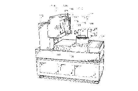
Referring now to Figures 4-7, the apparatus of the preferred
embodiment is illustrated therein. The apparatus of the preferred
embodiment comprises a massive granite base 102 supporting a first slide
table 104 which is movable along the longitudinal axis of the apparatus,
25 hereinafter referred to as the X-axis. A rotary table 106 is mounted on the
first slide table 104. The rotary table 106 is rotatable about a designated
CA 02220371 1997-11-06
Z-axis, in a direction designated by ac in Figure 4. A tool spindle 108 is
mounted on the rotary table 106 and has a cup-shaped cutting tool 110
affixed to the arbor thereof.
The app~lus ofthe pl~re-led embodiment also comprises a pair of
5 upright massive granite blocks 112 mounted on one end of the granite base
102. A second slide table 114 is affixed to the upright granite blocks 112
and is movable horizontally in a direction perpendicular to the longitudinal
axis, hereinafter referred to as the Y-axis. The second slide table 114
supports a third slide table 116 and a lens holder 118, in which an
ophth~lmic lens blank 120 is mountable. The third slide table 116 is
movable vertically along the designated Z-axis.
The cutting tool 110 comprises a cup-shaped body 130 having at
least two cutter inserts 132 made of a material cont~ining tungsten-carbide
15 or similar elements. The outside diameter of the cutting tool 110 is
generally around 125 or 150 millimeters.
The slide tables 104, 114, and 116 and the rotary table 106 are
preferably mounted on high precision pressurized fluid bearings. The slide
tables are actuated by high-precision, linear-type servo-actuators. Since
20 such fluid bearings and linear servo-actuators are well-known generally,
they have not been illustrated, except for reference purposes, part of the
actuator of the third slide table as indicated by numeral 134 in Figures 4
and 6.
Although these types of fluid bearings and linear servo-drives are
25 known generally in the field of high-precision machining, these equipment
are rarely used in ophth~lmic lens generating equipment. The use of such
CA 02220371 1997-11-06
linear actuators and fluid bearings in the apparatus of the preferred
embodiment has been found to be an outstanding substitute for the
conventional lead screw and servo-motor drives. The inherent defects of
the conventional lead screw and servo-motor drives are numerous and
5 include the eccentricity of ball nut, backlash, thread irregularities and
flexion in the lead screws. These problems are practically nonexistent with
linear servo-actuators and pressurized fluid bearings.
The p.erel.ed method of operation of the apparatus of the ~lerelled
embodiment is illustrated in the examples of Figures 8-12. In Figures 8A,
8B, 8C and 8D for example, the initial position in the tool spindle 108 at
the beginning of a cut is represented in Figure 8A. The final position of
the tool spindle 108 at the end of a cut is illustrated in Figure 8B. The
cutting of the lens surface is done by rotating the rotary table 106 in the
clockwise direction when looking at the apparatus from the top. The
engagement of the cutting tool 110 with the lens blank 120 during a cut is
effected starting at the far edge of the lens blank 120 and moving through
the surface of the lens blank 120 toward the inside edge of the lens blank
120. The cutting tool 110 typically contacts the lens blank 120 in a
retracting, back-of-the-hand-type-motion against the surface of the lens
20 blank 120, although a forward movement is also possible.
Referring now to Figures 8C, there is illustrated therein the initial
and final positions of the lens holder 118 along the second slide 114. The
initial and final positions of the lens holder 118 are indicated by a
25 dimension label Dyl. Figure 8C also illustrates the initial and final
positions of the cutting edge of the tool 110 and the initial and final
positions of the rotary table 106 along the X-axis of the apparatus of the
16
CA 02220371 1997-11-06
preferred embodiment. The initial and final positions of the cutting edge
of the tool 110 are separated by the (lim~nsion label Dy27 and the initial and
final positions of the rotary table 106 are separated by the ~limen~ion label
DX.
The cutting edge of the tool 110 of the apparatus of the preferred
embodiment is spaced from the vertical axis, or the center of rotation of the
rotary table 106, a nominal radius indicated by numeral 122. The length
of the radius 122 contributes to the advantages of the apparatus of the
~lcr~ d embodiment over equipment of the prior art as will be explained
lo in the next pages.
Figure 8D illustrates the diameter D~ of the lens blank used for the
example of Figures 8A and 8B, and the depth of the cut DEPT}I
corresponding to the diopter value of the base curve cut in that lens.
The following Tables 1, 2 and 3 provide data and results for the
example of Figure 8A, 8B, 8C and 8D, as well as for four additional
examples carried out with different lens curvatures. The four additional
examples are illustrated respectively in Figures 9A-12D. Table 1 shows
the diopter values of the base curves and cross curves, and the
corresponding radii of the base curves in millimeter, for the five examples.
The radii of the base curves were calculated according to the following
formula:
Radius in millimeter = lOOO*(refractive index - l)/Diopter value of the
base curve. A refractive index of 1.53 (tool index) was used in the
calculations.
The examples are demonstrated with a cutting tool 110 having a
diameter of 152.4 mm, a lens blank 120 having a diameter of 70 mm and
17
CA 02220371 1997-11-06
a radius 122 between the cutting edge of the lens surfacing tool and the
center of rotation of the rotary table of about 205 mm. Table 2 and 3
illustrate the recorded values for DEPT~I~ DX, Dyl and Dy2 corresponding to
each example.
Table 1
Diopter Diopter Radius *
Examples Base culveCross curve Base curve
Fig. 8C -3.54 -6.25 149.7
Fig. 9C -4.00 -7.19 132.5
Fig. IOC -7.29 -8.10 72.6
0 Fig. llC -6.40 -6.40 82.8
Fig. 12C -6.37 -9.56 83.2
Table 2
* * X-ratio
Examples Depth Dx (DX/Deptb)
Fig. 8C 1.0 64.0 64.0/1
Fig. 9C 1.2 100.6 83.8/1
Fig. IOC 2.1 108.2 51.5/1
Fig. IIC 1.9 122.1 64.2/1
Fig. 12C 1.8 134.1 74.5/1
CA 02220371 1997-11-06
Table 3
* * Y-ratio
Examples Dyl DY2 (Dyl+Dy2)/
Fig.8C 6.5 78.1 1.2/1
Fig.9C 22.1 47.8 1.0/1
S Fig.lOC 107.2 176.9 4.1/1
Fig.llC 65.5 135.6 2.9/1
Fig.12C 52.7 122.3 2.5/1
* These dimensions are expressed in millimeters.
A ratio of the total displ~cement DX of the rotary table 106 along the
10 X-axis over the depth of cut DEP~ in the lens blank is also shown in Table
2. It is important to observe that the values ofthis ratio range between 50/l
and 80/1. For comparison purposes, the aforesaid corresponding ratio for
the machines of the prior art is about 1/1.
The precision of the apparatus of the preferred embodiment in the
15 generation of a base curve in a lens blank is thereby greatly advantaged
over the apparatus of the prior art. The advance of the tool towards the
lens surface is a compound movement of the rotary table and the retracting
movement of a linear actuator of the X-axis. The result of that compound
movement is that the increments by which the tool is advanced towards the
20 lens blank is about between 50 and 80 times smaller than the nominal
increment of the servo-actuator controlling the movement of the tool along
the X-axis. Hence, the resolution of the servo-actuator controlling the X-
axis is enhanced by the same factor.
19
CA 02220371 1997-11-06
The compoundmovement ofthe tool 110 along the X- axis greatly
explains the outstanding surface qualities which are obtainable on the
ophth~lmic lenses generated by the appalatus of the preferred embodiment.
The surfaces generated by the a~pal~lus of the preferred embodiment are
5 a final finish, and no further polishing is required.
Referring now to Table 3, there is illustrated therein the Y-ratio
representing the sum of the displacement of the tool 110 and the lens
holder 118 along the Y-axis ofthe al)pal~lus divided by the diameter of the
lens blank 120. The sweeping the tool 110 across the surface of the lens
blank 120 is also a compound movement of the rotary table 106 and the
linear servo-actuator of the Y-axis. The Y-ratio of Table 3 indicates that
in the examples of Figures 8-12, the total number of programmed
increments transmitted to both actuators is in most cases larger than the
actual number of increments contained in the diameter of the lens blank
15 120. Therefore, the resolution of both actuators controlling the Y-axis is
similarly enhanced. This feature also contributes to some degrees to
providing the olltct~n~1ing surface quality on the ophth~lmic lens generated
by the appalalus of the preferred embodiment.
Other advantages of the compound movements of the cutting tool
20 110 include the ability of the appalalus of the preferred embodiment to
generate a multitude of surfaces on optical lenses. To name a few, the
apparatus of the preferred embodiment can generate concave and convex
surfaces, flat surfaces, toroidal surfaces, straight cylindrical surfaces,
saddle point sllrf~ce,s, variable toroidal, elliptical toroidal or other complex25 sllrf~ces The a~ lus ofthe ~ relled embodiment can also add prism to
a generated lens without inclining the lens relative to its axis.
CA 02220371 1997-11-06
While ~e above description provides a full and complete disclosure
of the preferred embodiment of this invention, various modifications,
~ltem~te constructions and equivalents may be employed without departing
from the true spirit and scope of the invention. Such changes might involve
5 alternate mat~ri~, components, structural arrangements, sizes,
construction features or the like. Therefore, the above description and the
illustrations should not be construed as limitin~ the scope of the present
invention which is defined by the appended claims.