Note : Les descriptions sont présentées dans la langue officielle dans laquelle elles ont été soumises.
, CA 02220844 1997-11-12
HIGH INTENSITY MIXER
CONTROL SYSTEM AND METHOD
LO OF THE INVENTION
This invention relates to a method and system of controlling the
mi~in of a batch of material in a high intensity mixer so that batches of t~e
10 same compositions of material and weight are mixed to produce a molten
mixture having essentially the same predetermined consistent physical state.
BACKGROUND OF THE INVEN'rION
High intensity batch mixers consist of a cylindrical processing
chamber in which rotating blades mounted on a drive shaft are driven by an
electric motor to rotate at tip speeds of at least 10, and usually at least about
20, meters per second.
Such mixers have a means of feeding material into the mixer and a
discharge means consisting of a discharge gate. A batch of material in the
mixer is heated by the action of the rotating blades striking and impelling the
materials to impact on the internal surfaces and other particles in the enclosed2 5 chamber. This action is sometimes referred to as the thermo-kinetic effect or
inner frictional heating.
Such mixers are used to mix or blend small pieces or particles of
m~teri~l which may vary in size typically from powder to larger than one-half
3 o inch and which comprise or include meltable plastic particles which may, forinstance, be particles of recycled thermoplastic material. These meltable plastic
particles are transformed by frictional heating from a solid state through a
softening stage to a flowable melted or molten state. In the softening
transition stage between the solid and molten states, such softening particles
. CA 02220844 1997-11-12
convert the initial free flowing particles into a viscous mass, the degree of
viscosity of which depends upon the nature of the material being mixed.
After reaching the molten state, at which point the viscosity of the mixture
falls off rapidly, the material is further heated to the desired temperature and5 then discharged from the cylindrical processing chamber and delivered to a
further processing step usually in the form of a molding operation.
At present, the mixing is controlled through measurement of the
internal temperature in the mixing chamber, that is, in effect the temperature of
10 the mixture and, when a certain temperature is reached, the mixer is caused to
discharge the batch through its discharge gate.
The present temperature governed control system lacks precision
because of variable ambient temperature conditions in the mixer depending on
its operating mode or cycle. As a result, undesirable variations can occur in
the physical state of the mixed batches of the same materials and weight
which adversely affect further processing of the batch.
It is the object of the present invention to overcome this problem
2 o whereby mixtures of batches of the same material and weight discharged from
the mixer will consistently be in essentially the same physical state.
Another object of the invention is to enable the mixing of the
batches to be instantaneously and continuously monitored throughout their
25 transition stages of softening, melting and reaching final discharge state.
Still another object is to provide a mixer control system for
automatic batch processing.
SIIMMARY OF THE INVENTION
The invention in its broadest aspects is directed to a method and
apparatus for controlling the mixing of batches of material of known weight
~ ~CA 02220844 1997-11-12
and composition or recipe in a high intensity mixer by continuously measuring
instantaneous power input to the mixer motor commencing with the
introduction of the batch of material to be mixed, accumulating such
instantaneous power inputs to measure the electrical energy input to said
5 motor, and discharging the mixed batch after a predetermined level of
electrical energy input has been delivered to said motor.
More particularly, in its preferred form the invention resides in a
method involving and apparatus for measuring the instantaneous power input
10 to the mixer motor, sllmmin~ such power inputs commencing with the
introduction of the batch of material, generating a signal of pulses of discreteenergy quantums in response to said sl-mming, delivering said pulsed signal to
a counter, setting the counter to deliver a signal to discharge said batch upon
said counter receiving a predetermined number of pulsed signals.
Still further the inventor provides for automatic batch mixing of a
series of batches of a specified recipe or mixture and weight of material with
each batch mixing precisely controlled to produce the same desired physical
state consistency.
These and other features of the invention will be apparent from the
following detailed description with reference to the accompanying drawing.
2 5 l~RIEF DESC~PTION OF THE DRAVVINGS
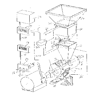
The Figure is a diagr~mm:~tic view illustrating a high intensity
control system in accordance with the invention as applied to an automated
batch mixing system.
. . 'CA 02220844 1997-11-12
.,
~ETAILED DESCRIPrION ACCORDING TO THE PREFERRED
l~MBODIMENTS OF THE PRESENT lNVENTION
As illustrated in the Figure, a high intensity mixer generally
5 designated a 1 comprises a cylindrical mixing chamber 2 in which blades 3
mounted on a drive shaft 4 are driven at high peripheral speeds by an electric
motor 5.
Feed into the mixing chamber 2 is delivered from a hopper 6 by a
10 worm drive 7. The mixing chamber 2 has a discharge outlet 8 which is open
and closed by a gate 9 operated by an air or hydraulic cylinder 10 through a
linkage system generally designated at 11.
When the charge of material to be mixed is introduced into the
15 mixing chamber 2 via the hopper 6 and worm drive or screw feed 7, the
particles which include meltable plastic particles are thrown violently togetherand against the walls of the mixing chamber by the blades 3 rotating at high
speeds with their tip speeds usually being at least about 20 meters per second
or higher. Due to the thermo-kinetic effect or inner frictional heating, the
2 o meltable plastic particles are transformed from a solid state through a softening
stage to a flowable melted or molten state. In the softening transition stage
between the solid and molten states, such softening particles convert the
initial free flowing particles into a viscous mass the degree of viscosity of
which depends upon the nature of material being mixed. Once the molten
2 5 state is reached, the viscosity of the mixture falls off rapidly and the mixture is
further heated to a desired temperature ready for discharge at which point the
gate 9 is opened through the cylinder 10 and the heated mixture almost
instantly discharged under the centrifugal force of the rotating blades.
3 o An almost unlimited mixture of materials can be mixed in a high
intensity mixer involving, in addition to the meltable plastic particles, for
example, particles of thermoset materials, metals, fibrous materials, rubber
materials, grain husks, shells etc. as well as fly ash, sand and the like. The
meltable plastic particles may be particles of recycled thermoplastic materials
CA 02220844 1997-11-12
so that a typical mixture of mixable materials will comprise recycled and waste
m~t~
According to the invention, a standard mixing time is set for each
5 desired material mixture of a given weight. The standard for this mixture or
recipe of materials is set by operating the mixer with test batches of the
material until the desired consistency of the resulting mixture discharged from
the mixer is obtained. Each time a test batch is run the electrical energy to the
electric motor 5 commencing with the introduction of the test batch until its
10 discharge is recorded. When a batch is mixed and discharged having the
desired llltim~te consistency, the electrical energy input to the motor for the
batch is recorded. Thereafter the mixing time of batches of the same
composition and weight is set by supplying the same energy input to the
electric motor commencing with the introduction of the batch into the mixer
15 as was recorded for the mixing of the successful test batch.
Similarly, an electric energy input to the mixer motor 5 is determined
for each composition of m~tçri~l and weight of each batch to be mixed in the
mlxer.
The required electrical energy input for proper mixing of each batch
recipe is recorded and may, for instance, be stored in a computer or
microprocessor as hereinafter more fully explained.
The measurement of the electrical power input to the electric motor
5 is accomplished by passing the power input lines 12 feeding the motor 5
through a power cell 13 such as is available from Load Controls Incorporated
of Sturbridge, Maryland.
The power cell 13 senses the instantaneous power input to the
motor and delivers it as an analogue power signal to a power and energy
meter 14 such as the KWH-2 power and energy meter available from the said
Load Controls Incorporated. Such a meter provides for the display of the
instantaneous power sensed by the power cell 13 and delivered as an
CA 02220844 1997-11-12
analogue power signal through the feed line 15 and as well sums the
accum~ ting electrical energy over time and can be selected to display the
energy input in terms of kilowatt hours (KW hours) and kilowatt minutes (KW
minlltes) or kilowatt seconds (KW seconds).
As the mixing of the batch of material in a high intensity mixer with
which the present invention is concerned, the mixing time only takes a few
seconds so that the power and energy meter 14 is set to measure the energy
input in terms of KW seconds.
The summ~tion of the energy input to the motor as measured by the
power and energy meter 14 is outputted on line 16 as a pulsed signal with
each pulse representing 1 KW second. The pulses are delivered on line 16 to a
counter 17 which, as hereinafter more fully explained, when reaching a
15 predetermined count following the introduction of the batch of material to be mixed into the mixing chamber 2 of the high intensity mixer affects the
opening of the gate 9 whereupon the batch is discharged through the
discharge opening 8 in the wall of the mixing chamber.
2 o In operation, the high intensity mixer will normally be operating at
idle speed prior to the introduction of the batch of material to be mixed. The
power cell 13 will be continuously monitoring the power input necessary to
drive the mixer while idling representing the idle load of the mixer. This idle
load which causes a continuous signal feed through line lS to the power and
energy meter 14 may be balanced out by an external potentiometer normally
provided for zeroing out the idle load so that the power and energy meter can
monitor the instantaneous power and the accumulating energy for the net
load only. That is, there will be no pulse outputs from the power and energy
meter 14 outputted on the line 16 to the counter 17 while the mixer is idling.
Alternatively, it may be desirable to track and note the energy
consumption of the mixer while idling in which case it becomes necessary to
set the counter 17 to zero at the instant the batch of material is delivered to
the mixing chamber.
CA 02220844 1997-11-12
It will be understood that the predetermined count entered into the
counter 17 at which predetermined count the batch of material will be
discharged from the mixer depends upon how the system was operated in
5 arriving at the count set for that weight of that composition of material as
explained above. If the count was set with the power and energy meter set to
zero out idle load, then the count would be smaller than if a count was set
including the idle load during the mixing of the batch.
To handle an individual batch where the power and energy meter is
set to zero out the idle load of the mixer, all that is necessary after setting the
counter to the predetermined count for that batch is to dump the batch into
the hopper 6 where it is almost instantaneously delivered into the mixing
chamber 2 to be mixed by the blades 3 and, when the predetermined count is
reached, a signal is delivered by the line 18 to the cylinder 10 to open the gate
9 discharging the mixed material.
If a series of batches are going to be mixed, then the system can be
automated by employing a suitable delivery system such as the weigh scale
2 o dispense system available from McGuire Products Inc. of Media,
Pennsylvania.
Such a system includes a weigh bin 19 fed from a large supply
hopper 20 into which a large quantity of the m~teri~l to be mixed is dumped.
25 The interaction between the supply hopper 20 and the weight bin 19 is such
that, as diagr~mm~tically illustrated, a cylinder 21 is arranged to operate a gate
22 to allow materials to feed into the weight bin 19 which is set to close the
gate 22 when a predetermined weight of material is delivered thereto at which
time a signal is delivered through a control switch 23 providing connections
3 o between the supply hopper cylinder 21 and the weigh bin operating cylinder
24 and its associated weight sensing mech~ni~m (not shown).
With the mixer running at idle speed and the mixer gate 9 closed as
signalled to the weight bin cylinder 24 via the line 25, the cylinder 24 will be
CA 02220844 1997-11-12
operated to retract the weigh bin gate 26 at which point the batch of material
will be delivered into the hopper 6 and into the mixing chamber 2.
If the power and energy meter has been set to zero out the idle load,
5 then KW second pulses will be fed on line 16 to the counter 17 which will
have had the predetermined count to be reached for opening the mixer gate 9
set therein. Upon the counts received by the counter 17 on the line 16
reaching the predetermined set count, the signal will be delivered via the line
18 to open gate 9 and discharge the mixed batch.
Alternatively, if the power and energy meter does not have the idle
load of thé mixer zeroed out, a signal will be fed to the counter 17 via the line
27 from control switch 23 to set the counter at zero the instant the batch of
material is released from the weigh bin 19.
It will be understood that once the batch of material from the weigh
bin 19 is released into the hopper 6, the weigh bin gate 26 will close sending asignal via the control switch 23 to open the gate 22 of the supply hopper to
commence refilling the weigh bin.
If the mixer has completed its mixing of the previous batch and
discharged same prior to the completion of the filling of the weigh bin with
the desired weight of material, the gate 9 will have opened and reclosed and
the subsequent batch as soon as its full weight has been reached will then be
25 dumped into the hopper 6 and the cycle repeated. Should the weigh bin be
filled before completion of the mixing of the previous batch has been
completed, then the signal to be fed by the line 25 to the weigh bin gate will
be made a function of a cycle of first opening and then closing the discharge
gate 9.
As explained, the predetermined counts for a wide range of batch
recipes may be set and can be stored in a computer 28 and, when running a
series of one of these batch recipes, the computer can deliver the appropriate
,
, CA 02220844 1997-11-12
count number to the counter 17 or the counter may be part of the computer
28.
It will be understood that variations in details may be made without
5 departing from the scope of the appended claims.