Sélection de la langue

Search

Sommaire du brevet 2221663 

Énoncé de désistement de responsabilité concernant l'information provenant de tiers

Une partie des informations de ce site Web a été fournie par des sources externes. Le gouvernement du Canada n'assume aucune responsabilité concernant la précision, l'actualité ou la fiabilité des informations fournies par les sources externes. Les utilisateurs qui désirent employer cette information devraient consulter directement la source des informations. Le contenu fourni par les sources externes n'est pas assujetti aux exigences sur les langues officielles, la protection des renseignements personnels et l'accessibilité.

Disponibilité de l'Abrégé et des Revendications

L'apparition de différences dans le texte et l'image des Revendications et de l'Abrégé dépend du moment auquel le document est publié. Les textes des Revendications et de l'Abrégé sont affichés :

  • lorsque la demande peut être examinée par le public;
  • lorsque le brevet est émis (délivrance).
(12) Demande de brevet: (11) CA 2221663
(54) Titre français: PINCE A RESSORT POUR UN APPAREIL D'ECLAIRAGE ENCASTRE
(54) Titre anglais: SPRING CLIP FOR A RECESSED LIGHT FIXTURE ASSEMBLY
Statut: Réputée abandonnée et au-delà du délai pour le rétablissement - en attente de la réponse à l’avis de communication rejetée
Données bibliographiques
Abrégés

Abrégé anglais


A spring clip for securing a light fitting into a light fixture housing
and for securing the light fixture housing to a ceiling structure is formed of
two leg sections. A first leg section has a tongue portion to contactingly
engage the light fitting. The spring clip extends through a slot in the light
fixture housing extending outside thereof to engage the ceiling structure.

Revendications

Note : Les revendications sont présentées dans la langue officielle dans laquelle elles ont été soumises.


CLAIMS
1. A spring clip for securing a light fitting into a light fixture
and for securing the light fixture to a ceiling structure comprising an
elongated body defining a first leg section and a second leg section bent
relative to said first leg section;
said first leg section having inner and outer surfaces and an
integral resilient tongue portion extending outwardly from said outer surface;
said tongue portion having, at a free end thereof, a light fitting
contacting protuberance;
said first leg section having, at a free end thereof, a light
fixture-engaging flange;
said second leg section defining a first portion contiguous with
and inclined relative to said first leg section and a second portion bent
relative to said first portion and having a free end adapted for contacting saidceiling structure.
2. A spring clip as defined in claim 1, wherein said body is
metallic and said integral resilient integral tongue portion is a punched-out
section of said first leg section.
3. A spring clip as defined in claim 1, wherein said fixture-engaging
flange has a restricted width relative to that of said body.
4. A spring clip as defined in claim 3, wherein said first leg
section includes opposite outwardly bent wing portions connecting said
flange to said first leg section.

5. A spring clip as defined in claim 1, wherein said first
includes portion of said second leg portion includes a stopper projection
extending outwardly from an inner surface of said inclined portion.
6. A spring clip as defined in claim 5, wherein said body is
metallic and wherein said stopper projection is a punched-out section of said
first inclined portion.
7. A spring clip as defined in claim 1, wherein the free end
of the second portion of said second leg section defines a horizontal flange
adapted to contact the ceiling structure.
8. A recessed light fixture assembly adapted to be mounted
in an opening of a ceiling structure, comprising:
a generally cylindrical light fixture housing having a wall and an
opened end; said wall having slot means therein; said wall, at said free end,
displaying a peripheral flange adapted for contacting said ceiling structure;
spring clip means engaged in said slot means; said spring clip
means having an elongated bent body defining a first leg section extending
in said housing and a second leg section extending outside said housing;
said first leg section having inner and outer surfaces and a resilient integral
tongue portion extending outwardly from said outer surface; said tongue
portion having, at a free end thereof, first engaging means; and
light fitting means adapted for mounting in said housing; said
fitting means defining an annular body having a generally cylindrical wall and
second engaging means thereon;
whereby insertion of said light fitting means in said housing
causes said cylindrical wall of said annular body to flex said resilient tongue
portion of said spring clip means inwardly allowing said light fitting means to

be securely received in said housing as said first and second engaging
means inter-engaged; removal of said light fitting means from said housing
being achieved by exerting a pulling force thereon causing the tongue
portions of said spring clips means to flex to disengage the inter-engaged
first and second engaging means from one another.
9. A recessed light fixture assembly as defined in claim 8,
wherein said cylindrical wall of said annular body includes a annular flange
adapted for covering said peripheral flange of said cylindrical housing.
10. A recessed light fixture assembly as defined in claim 8,
wherein said slot means consist of a pair of vertically spaced openings in
said cylindrical wall of said housing; one of said openings being disposed
adjacent said annular flange and a second of said openings being disposed
inwardly on said cylindrical wall of said housing; said elongated bent body
extending through said second opening.
11. A recessed light fixture as defined in claim 8 wherein
said first engaging means consist of a rounded protuberance and said
second engaging means consist of a peripheral rounded groove on said
cylindrical wall of said light fitting means.
12. A recessed light fixture assembly as defined in claim 8,
wherein said elongated bent body is metallic and said integral resilient
integral tongue portion is a punched-out section of said first leg section.
13. A recessed light fixture assembly as defined in claim 8,
wherein said first leg section has, at a free end thereof, a horizontal gripping

flange having a width smaller than that of the remaining part of said first leg
section.
14. A recessed light fixture assembly as defined in claim 13,
wherein said first leg section further includes opposite outwardly bent wing
portions connecting said flange to said remaining part.
15. A recessed light fixture assembly as defined in claim 8
wherein said second leg portion includes an inclined portion having a stopper
projection extending on an inner surface thereof.
16. A recessed light fixture assembly as defined in claim 15,
wherein said elongated bent body is metallic and wherein said stopper
projection is a punched-out section of said inclined portion.
17. A recessed light fixture assembly as defined in claim 16,
wherein a free end of said second leg section defines a horizontal flange
adapted to contact the ceiling structure.

Description

Note : Les descriptions sont présentées dans la langue officielle dans laquelle elles ont été soumises.

CA 02221663 1997-11-20
TITLE OF THE INVENTION
Spring clip for a recessed light fixture assembly.
FIELD OF THE INVENTION
The present invention refers generally to recessed ceiling
5 lighting fixtures and, more particularly, it relates to an improved spring clip for
holding a light fitting into a light fixture and for securing the light fixture to a
ceiling structure.
BACKGROUND OF THE INVENTION
Various types of light fixture supporting clips are known. For
example, in U.S. patent 4,739,460 issued April 19, 1988 to Kelsall, there is
described a recessed remodelling light fixture adapted for mounting in an
opening within a ceiling. A pair of snap spring clips of special configuration
are utilized for holding the cylindrical fixture housing within the ceiling. Theclips are disposed in elongated slots which are vertically aligned within the
15 wall of the housing. During installation, the spring clips are rotated outwardly
through the slots to bear against the upper sub-ceiling surface for securely
retaining securely the housing within the ceiling.
In this U.S. patent, nor in the prior art uncovered in a search
directed to the present subject matter, a spring clip is disclosed which serves
20 the dual purpose of securing the fixture housing to the ceiling structure as
well as securing a light fitting or trimming to the light fixture.
STATEMENT OF THE INVENTION
It is therefore an object of the present invention to provide a
spring clip which, while securing a light fixture housing to a ceiling structure,
25 also serves to allow easy and rapid insertion and removal of a light fitting or
trimming to the light fixture housing.

CA 02221663 1997-11-20
This is achieved by providing a spring clip which, in accordance
with the present invention, comprises an elongated body that defines a first
leg section and a second leg section bent relative to the first leg section; thefirst leg section has inner and outer surfaces and an integral resilient tongue
5 portion that extends outwardly from the outer surface. The tongue portion
has, at a free end thereof, a light fitting contacting protuberance. While the
first leg section has, at a free end thereof, a light fixture engaging flange, the
second leg section consists of a first portion contiguous with and inclined
relative to the first leg section and a second portion bent relative to the first
10 portion and has a free end adapted for contacting the ceiling structure.
The present invention also relates to a recessed light fixture
assembly which is adapted to be mounted in an opening of a ceiling
structure. It comprises:
a generally cylindrical light fixture housing having a wall and an
15 opened end; the wall having slot means therein; the wall, at the free end,
displaying a peripheral flange adapted for contacting the ceiling structure;
spring clip means engaged in the slot means; the spring clip
means having an elongated bent body defining a first leg section extending
in the housing and a second leg section extending outside the housing; the
20 first leg section having inner and outer surfaces and a resilient integral
tongue portion extending outwardly from the outer surface; the tongue
portion having, at a free end thereof, first engaging means; and
light fitting means adapted for mounting in the housing; the
fitting means defining an annular body having a generally cylindrical wall and~5 second engaging means thereon;
whereby insertion of the light fitting means in the housing
causes the cylindrical wall of the annular body to flex the resilient tongue
portion of the spring clip means inwardly allowing the light fitting means to besecurely received in the housing as the first and second engaging means
30 inter-engaged; removal of the light fitting means from the housing being

CA 02221663 1997-11-20
achieved by exerting a pulling force thereon causing the tongue portion of
the spring clip means to flex to disengage the inter-engaged first and second
engaging means from one another.
Other objects and further scope of applicability of the present
invention will become apparent from the detailed description given
hereinafter. It should be understood, however, that this detailed description,
while indicating preferred embodiments of the invention, is given by way of
illustration only, since various changes and modifications within the spirit andscope of the invention will become apparent to those skilled in the art.
BRIEF DESCRIPTION OF THE DRAWINGS
Figure 1 is a perspective view showing a light fixture housing
mounted to a ceiling structure by means of clips made in accordance with the
present invention;
Figure 2 is a side elevation view of the clip;
Figure 3 is a front elevation view thereof;
Figure 4 is a rear elevation view thereof;
Figure 5 is a top plan view thereof;
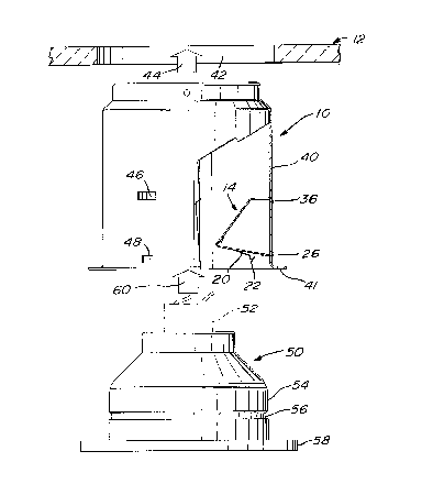
Figure 6 is an exploded view showing the components of the
light fixture assembly to be mounted to a ceiling structure;
Figure 7 is an elevational view showing the assembly of the
components of figure 6; and
Figure 8 is an enlarged cross sectional view of the lower right
corner shown in figure 7, the light fitting having been removed.
DESCRIPTION OF PREFERRED EMBODIMENTS
Referring to figure 1, there is shown a light fixture housing 10
being mounted to the subceiling surface 12 of a ceiling structure by means
of a series of clips 14.

CA 02221663 1997-11-20
Referring more particularly to figures 2-5, each clip 14 is formed
of a first leg section 16 and of a bent second leg section 18. The first leg
section 16 extends vertically and displays, in the center thereof, an outwardly
projecting punched-out tongue portion 20 having, at its free end, a semi-
5 circular protuberance 22. The lower end of the leg section 16 has a
L-shaped restricted portion 24 including a horizontally extending edge 26.
Adjacent the restricted lower portion 24 is a pair of opposite frontwardly
projecting triangular shaped wing extensions 28 and 30, the function of which
will be described further hereinbelow.
The second leg portion 18 comprises an inclined first portion
30, the upper end of which displays a punched-out projection 32. The
second leg section 18 also includes a vertically extending lower portion 34
with a horizontally extending edge 36.
The clip is preferably constructed of a resilient material such as
spring or sheet steel. This enables the clip to be formed in a simple bending
and stamping operation. The resiliency of the material further enables the
tongue portion to be flexed and the second leg section to also flex relative
to the first leg section.
Referring to figure 6, the light fixture housing 10 has a generally
cylindrical wall 40 with an opened end surrounded by an annular flange 41.
An opening 42 is made in a ceiling 12 so as to receive the housing as
indicated by arrow 44. The cylindrical wall 40 of the light fixture housing 10
has a pair of vertically spaced slots 46 and 48; there are preferably three
sets of these pairs of slots on the cylindrical wall of a housing. As illustrated
in figure 6, the edges 26 and 36 of the clip 14 extend through the slots 48
and 46, respectively, bearing against the outer face of the cylindrical wall.

CA 02221663 1997-11-20
Figure 6 also shows a light fitting or trimming, generally
denoted 50, in which is installed a light bulb 52. The light fitting has a
generally cylindrical outer wall 54 in which is provided a rounded groove 56.
The lower end of the light fitting is opened and has an annular flange 58
5 which, as can be seen in figure 7, covers the flange 41 of the light fixture
housing when the components are assembled.
To assemble the light fixture assembly, the light fitting 50 is
inserted, as indicated by arrow 60, into the cylindrical housing forcing the
spring clips to pivot and to adopt the position shown in figure 7. The leg
10 section 16 of the clip bears against the inner surface of the cylindrical
housing while the leg section 18 extends outside the housing with its lower
portion 34 resting against the subceiling surface of the ceiling structure.
During sliding entry, the tongue portion 20 of the spring clip contacts the wall54 of the light fitting until its protuberance 22 engages the peripheral groove
15 56 of the light fitting.
Figure 8 shows the possibility of having various thicknesses of
ceiling 12.
The punched-out portion 32 of the inclined portion 30 of the
second leg section 18 bears against the outer surface of the cylindrical wall
20 acting as a stopper preventing the clip from being dislodged during removal.
Also, figure 8 shows that, whenever it is desired to remove the spring clip
from the housing, a tool is inserted behind the wings 28 or 30 thus freeing
the lower portion edge 26 from its engagement in the slot 48; thereafter, the
second leg portion may be easily retracted through the slot 46.
Although the invention has been described above with respect
with one specific form, it will be evident to a person skilled in the art that it
may be modified and refined in various ways. It is therefore wished to have

CA 02221663 1997-11-20
it understood that the present invention should not be limited in scope,
except by the terms of the following claims.

Dessin représentatif
Une figure unique qui représente un dessin illustrant l'invention.
États administratifs

2024-08-01 : Dans le cadre de la transition vers les Brevets de nouvelle génération (BNG), la base de données sur les brevets canadiens (BDBC) contient désormais un Historique d'événement plus détaillé, qui reproduit le Journal des événements de notre nouvelle solution interne.

Veuillez noter que les événements débutant par « Inactive : » se réfèrent à des événements qui ne sont plus utilisés dans notre nouvelle solution interne.

Pour une meilleure compréhension de l'état de la demande ou brevet qui figure sur cette page, la rubrique Mise en garde , et les descriptions de Brevet , Historique d'événement , Taxes périodiques et Historique des paiements devraient être consultées.

Historique d'événement

Description Date
Inactive : CIB désactivée 2019-01-19
Inactive : CIB attribuée 2018-09-27
Demande non rétablie avant l'échéance 2002-11-20
Le délai pour l'annulation est expiré 2002-11-20
Réputée abandonnée - omission de répondre à un avis sur les taxes pour le maintien en état 2001-11-20
Inactive : Inventeur supprimé 2000-05-24
Inactive : Page couverture publiée 1999-06-16
Demande publiée (accessible au public) 1999-05-20
Inactive : CIB en 1re position 1998-03-20
Inactive : CIB attribuée 1998-03-19
Symbole de classement modifié 1998-03-19
Inactive : CIB attribuée 1998-03-19
Inactive : Certificat de dépôt - Sans RE (Anglais) 1998-02-11
Lettre envoyée 1998-02-11
Demande reçue - nationale ordinaire 1998-02-10

Historique d'abandonnement

Date d'abandonnement Raison Date de rétablissement
2001-11-20

Taxes périodiques

Le dernier paiement a été reçu le 2000-09-06

Avis : Si le paiement en totalité n'a pas été reçu au plus tard à la date indiquée, une taxe supplémentaire peut être imposée, soit une des taxes suivantes :

  • taxe de rétablissement ;
  • taxe pour paiement en souffrance ; ou
  • taxe additionnelle pour le renversement d'une péremption réputée.

Les taxes sur les brevets sont ajustées au 1er janvier de chaque année. Les montants ci-dessus sont les montants actuels s'ils sont reçus au plus tard le 31 décembre de l'année en cours.
Veuillez vous référer à la page web des taxes sur les brevets de l'OPIC pour voir tous les montants actuels des taxes.

Historique des taxes

Type de taxes Anniversaire Échéance Date payée
Enregistrement d'un document 1997-11-20
Taxe pour le dépôt - générale 1997-11-20
TM (demande, 2e anniv.) - générale 02 1999-11-22 1999-09-20
TM (demande, 3e anniv.) - générale 03 2000-11-20 2000-09-06
Titulaires au dossier

Les titulaires actuels et antérieures au dossier sont affichés en ordre alphabétique.

Titulaires actuels au dossier
BAZZ INC.
Titulaires antérieures au dossier
MICHEL MORAND
Les propriétaires antérieurs qui ne figurent pas dans la liste des « Propriétaires au dossier » apparaîtront dans d'autres documents au dossier.
Documents

Pour visionner les fichiers sélectionnés, entrer le code reCAPTCHA :


Pour visualiser une image, cliquer sur un lien dans la colonne description du document (Temporairement non-disponible). Pour télécharger l'image (les images), cliquer l'une ou plusieurs cases à cocher dans la première colonne et ensuite cliquer sur le bouton "Télécharger sélection en format PDF (archive Zip)" ou le bouton "Télécharger sélection (en un fichier PDF fusionné)".

Liste des documents de brevet publiés et non publiés sur la BDBC .

Si vous avez des difficultés à accéder au contenu, veuillez communiquer avec le Centre de services à la clientèle au 1-866-997-1936, ou envoyer un courriel au Centre de service à la clientèle de l'OPIC.

({010=Tous les documents, 020=Au moment du dépôt, 030=Au moment de la mise à la disponibilité du public, 040=À la délivrance, 050=Examen, 060=Correspondance reçue, 070=Divers, 080=Correspondance envoyée, 090=Paiement})


Description du
Document 
Date
(aaaa-mm-jj) 
Nombre de pages   Taille de l'image (Ko) 
Dessin représentatif 1999-06-14 1 9
Abrégé 1997-11-19 1 10
Description 1997-11-19 6 206
Revendications 1997-11-19 4 127
Dessins 1997-11-19 3 56
Courtoisie - Certificat d'enregistrement (document(s) connexe(s)) 1998-02-10 1 118
Certificat de dépôt (anglais) 1998-02-10 1 165
Rappel de taxe de maintien due 1999-07-20 1 114
Courtoisie - Lettre d'abandon (taxe de maintien en état) 2001-12-17 1 183
Rappel - requête d'examen 2002-07-22 1 128
Taxes 1999-09-19 1 43
Taxes 2000-09-05 1 40