Note : Les descriptions sont présentées dans la langue officielle dans laquelle elles ont été soumises.
CA 022223~2 1997-11-27
PATENT APPLICATION
Attorney Docket No. D/96664
SEU CLEANING IMAGING MATERIAL LEVEL DISPENSING SYSTEM
Disclosed in the embodiment herein is an improved imaging material
5 dispensing system for a reproduction apparatus, such as a xerographic or othercopier or printer, although not limited thereto, wherein a simple, low cost,
magnetic brush self cleaning system is provided for automatically cleaning the
inside of the imaging material dispensing container. Further disclosed is an
optical sensing system is provided for detecting the presence, absence, and/or
10 level of toner or other consumable imaging materials inside an imaging material
dispensing container from outside of the container, and wherein a simple, low
cost, magnetic brush self cleaning system is provided for automatically cleaningan optical window area inside of the imaging material dispensing container so
that an optical sensing system externally of the container may be employed for
15 optically sensing the presence, absence, and/or level of consumable imaging
material inside of the container.
As is well known, rt is desirable to provide a reliable means for
determining when addrtional imaging material needs to be provided for or
added to a reproduction apparatus which consumes such imaging material
20 during sheet or web printing operations. Various ~low toner~, toner level or toner
presence detecting systems have been developed and/or patented for
xerographic copiers and printers which determine when the internal supply
source of toner needs to be replenished, typically by signaling on an operator
display the need for refilling or replacing a toner dispensing supply container
25 when the undispensed toner therein approaches a preset low level or near
empty state. Some examples include U.S. Patent No. 3,920,155; 4,135,642; and
4,989,754. (This should be distinguished from alternative or addrtional systems for
CA 022223~2 1997-11-27
estimating ths consumption of toner, as in U.S. 5,349,377 and other references
cited therein.)
It is desi,aL,le that the toner level in the supply container sensing system
be low cost and reliable, and not occluded or contaminated by the particulate
5 toner material or the like. That is particularly a problem wHh an optical, i.e., light
beam, sensing system since most imaging matefials are effectively opaque. It is
desirable for these and other reasons not to have any, or as few as possible,
components of the optical sensing system within the imaging material
dispensing container itself. Not only because the components within the supply
10 container can become contaminated or jammed by the toner and/or other
imaging matefials, but also because n is desirable to make the imaging material
supply container recyclable and of low cost. It is desirable that the imaging
mulerk~ls be added to the reproduction apparatus with as little spillage or
contamination of the machine or the user as possible, preferably by removing a
15 simple, low cost, empty imaging matefials supply container and inserting a full
container rather than poufing loose material into an open container in the
machine.
Of particular background interest is U.S. 4,135,642, issued January 23,
1979 to John E. Forward et al, which shown an optical automatic low toner level
20 indicator with a lamp and photocell and a wiping arrangement provided inside
the dispenser to pefiodically clean the windows thereof. This patent particularly
illustrates some of the difficulties described above and elsewhere. If the tonerlevel sensing system is of the optical type, especially one depending on the
absence of interruption of a light beam by the toner in the container to indicate
25 that the toner level has fallen below the desired level in the container or other
input, it will be apparent from said 4,135,642 and elsewhere that contamination
by the toner matefial of either the light emitter or light receiver or sensor can
CA 022223~2 1997-11-27
also block the light beam therebetween, and thus trick the optical sensing
system into falsely signaling that there is still sufficient toner available in the toner
container, when there is not.
As is well known, such toner level or low toner detection and indicating
5 systems are desirable for warning the machine operator through a visual or
other display of the impending exhaustion of the toner supply and the need for
replacement. If the supply of toner becomes exhausted, there can be a
perce~tiL,le reduction in the density of the developed image and thus a
degradation in copy quality, wHh unacceptably light copies, and there may be
10 a long recovery period until the added fresh toner achieves the proper ratio of
carrier to developer in a two component developer mixing system such that
adequate copy quality is re-achieved. That is, H is very undesirable to let the
- reproduction apparatus actually run out of toner. Thus, H is particularly
important to have an accurate signal of the toner level reaching such a low
15 level in the toner dispensing container that it should be replaced, i.e., an ~early
warning~ of pending toner exhaustion.
By way of important background, various electrically biased magnet
brush cleaning systems are known for the different application of cleaning
residual toner from the surface of moving photoreceptor after the l~ ,srer of a
20 toner image therefrom. One example is Xerox Corporation U.S. 4,116,555 issued Sept. 26, 1978 to Eugene F. Young, et al..
Further by way of background, the exemplary toner dispensing
cylindrical rotating cartridge shown by way of one example hereinbelow of an
imaging material dispensing system, and its function and associated apparatus,
25 may be similar in other respects to that of Xerox Corporation U.S. 5,495,323 issued
Feb. 27, 1996 to Murray O. Meetze, Jr.. Thus, features thereof of only
background interest to the present invention, such as Hs particular rotatable
CA 022223~2 1997-11-27
drive and integral internal auger for leveling and transporting toner therein to a
dispensing outlet to replenish a development unH of a xerographic printer on
controlled demand, etc., need not be re-described in detail herein. Another
example of an internal auger rotating in with a cylindrical toner dispenser is
5 disclosed in Xerox Corporation U.S. 5,257,077. The present invention is not limited
to any such or other specific developer material dispensing system other than asindicated the claims.
A specific feature of the specific embodiment(s) disclosed herein is to
provide an imaging material dispensing container from which an at least
10 partially magnetically attractable consumable imaging material is dispensed for
saW reproduction apparatus, with an imaging material level sensing system for
sensing when there is an ins~,rficient quantity of said imaging material remaining
in said imaging material dispensing container, wherein said imaging material
level sensing system is positioned outside of said container to optically detect15 said insufficient quantity of said imaging material inside of said imaging material
dispensing container from outside of said container; said imaging material
dispensing container has at least one translucent wall area through which said
imaging material level sensing system can optically detect the presence of said
imaging material inside of said imaging material dispensing container; and a
20 magnetic brush cleaning system for internally cleaning said imaging material
from the inside of said translucent wall area of said imaging material dispensing
container to maintain relatively unobstructed sensing of said imaging material
by said imaging material level sensing system.
Further specific features disclosed herein, individually or in combination,
25 include those wherein said imaging material dispensing container is rotatable,
and wherein said magnetic brush cleaning system comprises a magnet
positioned outside of and adjacent to said imaging material dispensing
CA 022223~2 1997-11-27
container to form a magnetic cleaning brush inside of said imaging material
dispensin~a, container by magnetically attracting said magnetically attractable
imaging manerial to said translucent wall area of said imaging material
dispensing container; and/or wherein said imaging material dispensing
5 container is generally cylindrical and rotanable and said translucent wall area
thereof comprises a translucent annular band portion thereof; and/or wherein
said imaging manerial level sensing system comprises a light emitter source
positioned on one side of said imaging manerial dispensing container and a lightreceiving sensor substantially spaced therefrom on an opposing side of said
10. imaging material dispensing container for receiving and detecting light fromsaid light emitter source through said imaging manerial dispensing container;
and/or wherein said imaging manerial level sensing system comprises a light
emitter source and a light receiving sensor, and said imaging manerial
dispensing container is removably mounted between said light emitter source
15 and said light receiving sensor; and/or wherein said imaging material sensingsystem comprises a light beam source and a light receiver suL,alu~ lly spaced
therer,o,l, for receiving and detecting the light beam from said light beam
source; and wherein said imaging material dispensing container is removably
mounted in the path of said light beam from said light beam source between
20 said light beam source and said light receiver; and/or wherein said imaging
material dispensing container is rotanably driven, and wherein said magnetic
brush cleaning system comprises a stationary magnet mounted outside of and
adjacent to said imaging marterial dispensing container to form a magnetic
cleaning brush inside of said imaging material dispensing container by
25 magnetically attracting said magnetically attractable imaging material to said
translucent wall area of said imaging material dispensing container, and
wherein said translucent wall area comprises a translucent annular band portion
CA 022223~2 1997-11-27
thereof, and wherein said imaging material level sensing system comprises a
light emitter source positioned on one side of said imaging material dispensing
container and a light receiving sensor sub~la"lially spaced therefrom on an
opposing side of said imaging material dispensing container for receiving and
5 detecting light from said light emitter source through said translucent annular
band portion of said imaging material dispensing container cleaned by said
magnetic cleaning brush; and/or wherein a reproduction apparatus imaging
material dispensing system with an imaging material dispensing container from
which an at least partially magnetically attractable consumable imaging
10 material is dispensed for said reproduction apparatus, with an imaging material
level sensing system for sensing when there is an insufficient quantity of said
imaging material remaining in said imaging material dispensing container, and
wherein said imaging material dispensing container is a generally cylindrical
tubular container which is rotatably driven for said dispensing, a magnetic brush
15 cleaning system is provided for internally cleaning said imaging material from
the inside of said imaging material dispensing container, wherein said magnetic
brush cleaning system comprises a stationary magnet mounted outside of and
adjacent to said cylindrical imaging material dispensing container to form a
magnetic cleaning brush inside of said imaging material dispensing container by
20 magnetically attracting said magnetically attractable imaging material to said
interior of said imaging material dispensing container to clean said interior ofsaid imaging material dispensing container with said magnetic cleaning brush
as said cylindrical imaging material dispensing container is so rotatably driven;
and/or wherein said stationary magnet corresponds in length to the length of
25 said cylindrical imaging material dispensing container.
The disclosed system may be connected to and operated and
controlled by appropriate operation of conventional reproduction system
CA 022223S2 1997-11-27
control systems. It is well known and preferable to program and execute
imaging, ,~ lin~, paper handling, and other control functions and logic with
software instructions for conventional or general purpose microprocessors, as
taught by numerous prior patents and commercial products. Such
S programming or sof~ware may of course vary depending on the particular
functions, software type, and microprocessor or other computer system utilized,
but will be available to, or readily programmable without undue
experimentation from, functional desc,i~tions, such as those provided herein,
and/or prior knowledge of functions which are conventional, together with
10 general knowledge in the software and computer arts. Alternatively, the
disclosed control system or method may be implemented partially or fully in
hardware, using standard logic circuHs or single chip VLSI designs. The resultant
controller signals may conventionally actuate various conventional electrical
solenoid or cam-controlled motors or clutches, or other components, in
15 programmed steps or sequences.
As to specific components of the subject apparatus, or alternatives
therefor, it will be appreciated that, as is normally the case, some such
components are known per se in other apparatus or applications which may be
addmonally or alternatively used herein, including those from art cited herein, or
20 commercially available components, such as well known light em'~ter-sensor
pairs, and various well known magnets. ~I references cited in this specification,
and their references, are incorporated by reference herein where appropriate
for appropriate teachings of additional or alternative details, features, and/ortechnical background. What is well known to those skilled in the art need not
25 be described here.
Various of the above-mentioned and further features and advantages
will be apparent from the specific apparatus and its operation described in the
CA 022223~2 1997-11-27
example below, and the claims. Thus, the present invention will be better
understood from this description of one specific embodiment, including the
drawing figures (approximately to scale) wherein:
Fig. 1 is an exploded perspective view of one embodiment of an
5 exemplary toner dispensing container for a xerographic reproduction apparatus
for which the disclosed improved imaging materials level sensing system may be
employed, as show in the other Figures;
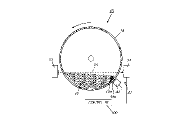
Fig. 2 is a schematic frontal view of one example of the subject
imaging materials level sensing system when the container of Fig. 1, shown here
10 in frontal end cross-section, is installed in an exemplary reproduction apparatus;
and
Fig. 3 is a schematic bottom view of the embodiment Fig. 2 with the
container partially cross-sectioned for visibility therein.
Describing now in further detail this exemplary embodiment with
15 reference to the Figures, only the relevant portions are illustrated since there is
no need to show the rest of an otherwise conventional reproduction machine
and its imaging system, such as is already shown in the above-c~ed issued U.S.
5,498,323, etc.. The reproduction machine is conventionally supplied with
conventional consumable toner, or toner plus carrier, imaging material 12 from
20 a generally cylindrical replaceable toner dispensing bottle or container 14
which is rotatably driven, as described in the above-cited U.S. 5,495,323 or
otherwise. The improved optical toner level sensing system 20 of which only
one example is shown here provides a simple yet more accurate early warning
to the customer that this container 14 is empty, or about to become empty, and
25 provides an internal self-cleaning function as well.
Referring to Figs. 2 and 3, it has been found that a two component
optical sensing system 20 having an emitter 22 and a detector 24 on opposite
CA 022223S2 1997-11-27
sides of the toner container 14, to define an effective light beam 26
therebetween at a preset level through the lower portion of the container 14,
provides a high signal to noise ratio. Since both the emHter 22 and detector 24
are completely outside of the toner container 14 they both also avoid toner
5 co,ltc,mination problems, as discussed above. Thus, the detection of the lightfrom emHter 22 by the detector 24 signals to the machine controller 100 the
absence of sufficient remaining toner in the container 14. Likewise, the sensed
obstruction (preferably wHh a time delay or integration) of the light beam 26 bythe detector 24 signals to the co"l,cl'~r 100 the presence of sufficient remaining
10 toner in the supply container 14. Various commercial components may be
employed for the optical toner level sensing system 20 light emHter 22 and
detector 24. For example, in this exemplary embodiment a commercial optical
transmissive sensor 24 such as model 130K54561 from Optek Technology, Inc.
may be utilized.
However, H was discovered as a significant problem in such an optical
toner level sensing system 20 that toner adhering to the inside wall(s) of the
container 14 can reduce the detectable optical radiance from the emitter 22
below the effective sensitivHy of the detector 24, particularly if this optical
sensing system 20 is used wHh toner containers 14 which are recycled or reused.
20 Typical low cost cleaning processes do not remove this toner contamination
from the inside walls of the container 14 sufficiently for this purpose. This toner
contamination of the walls of the container 14 causing this optical beam 26
obstruction is believed to be caused by static electricHy charges and toner
addHives. However, the particular theory of this toner adhesion problem is not
25 important to the solution for H, which the present system provides. This toner
contamination is not sufficiently removed by the rotation of the container 14 per
CA 022223~2 1997-11-27
se, or by thumping, tapping or other such typical mechanical agHation of toner
containers as are used for toner dispensing ussi~lunce.
The toner container 14 here is conventionally a relatively thin walled
container molded of a suHable conventional translucent plastic, such as high
5 densHy polyethylene, so as to be sufficiently.optically translucent for the optical
sensing system 20 absent the above discussed toner contamination problem. It
will be appreciated, however, that the container 14 need only be translucent
in the area through which the light beam 26 passes.
The present system provides an automatically cleaned window area
10. inside of the container 14, for optical l~uns~ission through both opposing walls
thereof of the light beam path 26 of this optical sensing system 20. This is
accomplished here by a simple fixed appropriately posHioned magnet 30
interacting wHh a portion of the imaging material inside the container 14. The
magnet 30 is posHioned outside of, non-crHically but relatively closely spaced
15 from, the rotating toner container 14. The magnet 30 is posHioned to extend
along the axis of the container 14 over at least the area of the light beam path26 of the o,~tical sensing system 20, or, as shown in Fig. 3, the full length of the
container 14. The magnet 30 has a magnetic field flux which extends inside the
adjacent portion of the container 14 to form therein a magnetic brush 1 2a from
20 a small quantHy of the imaging material 12 which is magnetically attractable. There are known single component magnetic toner systems wHh which this
system may be used. However, in this particular example, the toner is not ferrous
and not magnetically ull~atlJble, but is mixed with carrier beads which are.
This magnetic flux field can align and hold this carrier bead material therein. This
25 example of a two component imaging material 12 wHh steel, ferrHe, or other
magnetically attractable carrier beads is typical of a so-called ~trickle
development~ system, in which a small percentage of such carrier material is
CA 022223~2 1997-11-27
pre-mixed in and dispensed wHh the toner material to also gradually replace
the carrier in the printer 10 development unH fed the material by the container
14. This magnetically c.ll,~,~table material is attracted towards the magnet 30,and thus towards, and held stationary against, the inside wall of the toner
5 container 14 in at least the area 14a thereof, corresponding to the magnet 30
area.
As the container 14 rotates, this magnetic brush 12a sweeps or scrubs
at least an annual clean window area 14a of corresponding width to the
magnet 30 length inside the container 14. This cleaned, ~see-through~, window
10 area 14a is where the light beam path 26 of the optical sensing system 20
passes through the container 14, and this overcomes the above-discussed toner
contamination problems with the optical sensing system 20.
The size or strength of the magnet 30 is not crHical, but is empirically
selected to provide sufficient attractive force for adequate such cleaning for
15 the optical sensing system 20 by the magnetic brush 12a without excessive
friction or drag. That of course will vary depending on the particular imaging
material and container, etc.. The magnet 30 may be positioned as shown in Fig.
2, that is, posHioned below the optical detector 24 and under the container 14,
so as to form the magnetic cleaning brush 12a near the bottom of the
20 container 14.
There is an additional feature and function of the magnet 30 or
alternatives thereof not limited to cleaning a window area for the optical
sensor. The magnet 30 can be used is to make sure that most or almost all of
the imaging material is loosened and scraped off of the interior walls of the
25 container 14, thus dropping towards the bottom of the container 14 and being
dispensed. This lessen the excess undispensed and thus wasted material in the
container before H is replaced, and which material otherwise needs to be
1 1
CA 022223~2 1997-11-27
cleaned out and recovered during the process of recycling the used container.
To this end, the magnet 30 may optionally be made to extend for substantially
the full axial length of the container 14, as shown in the bottom view of Fig. 3, to
thereby form a magnetic cleaning brush T2a for the full length of the container
S interior. Furthermore, K the magnet is to be used only to help clean excess
material out of the container in this manner it may be mounted in other radial
positions around the container axis of rotation.
While the embodiments disclosed herein are presently preferred, it will
be appreciated from this teaching that various alternatives, modifications,
10 variations or improvements therein may be made by those skilled in the art,
which are intended to be encompassed by the following claims: