Sélection de la langue

Search

Sommaire du brevet 2223311 

Énoncé de désistement de responsabilité concernant l'information provenant de tiers

Une partie des informations de ce site Web a été fournie par des sources externes. Le gouvernement du Canada n'assume aucune responsabilité concernant la précision, l'actualité ou la fiabilité des informations fournies par les sources externes. Les utilisateurs qui désirent employer cette information devraient consulter directement la source des informations. Le contenu fourni par les sources externes n'est pas assujetti aux exigences sur les langues officielles, la protection des renseignements personnels et l'accessibilité.

Disponibilité de l'Abrégé et des Revendications

L'apparition de différences dans le texte et l'image des Revendications et de l'Abrégé dépend du moment auquel le document est publié. Les textes des Revendications et de l'Abrégé sont affichés :

  • lorsque la demande peut être examinée par le public;
  • lorsque le brevet est émis (délivrance).
(12) Demande de brevet: (11) CA 2223311
(54) Titre français: MACHINE DE FORAGE A PERCUSSION A AVANCE REGULEE
(54) Titre anglais: PERCUSSION BORING MACHINE WITH RUN MONITORING
Statut: Réputée abandonnée et au-delà du délai pour le rétablissement - en attente de la réponse à l’avis de communication rejetée
Données bibliographiques
(51) Classification internationale des brevets (CIB):
  • E21B 01/00 (2006.01)
  • E21B 04/14 (2006.01)
(72) Inventeurs :
  • HESSE, ALFONS (Allemagne)
(73) Titulaires :
  • TRACTO-TECHNIK PAUL SCHMIDT SPEZIALMASCHINEN
  • TRACTO-TECHNIK PAUL SCHMIDT SPEZIALMASCHINEN
(71) Demandeurs :
  • TRACTO-TECHNIK PAUL SCHMIDT SPEZIALMASCHINEN (Allemagne)
  • TRACTO-TECHNIK PAUL SCHMIDT SPEZIALMASCHINEN (Allemagne)
(74) Agent: SWABEY OGILVY RENAULT
(74) Co-agent:
(45) Délivré:
(22) Date de dépôt: 1997-12-02
(41) Mise à la disponibilité du public: 1998-06-04
Licence disponible: S.O.
Cédé au domaine public: S.O.
(25) Langue des documents déposés: Anglais

Traité de coopération en matière de brevets (PCT): Non

(30) Données de priorité de la demande:
Numéro de la demande Pays / territoire Date
196 50 271.3 (Allemagne) 1996-12-04

Abrégés

Abrégé français

Machine de forage à percussion à avance régulée. La machine de forage à avance régulée comporte un dispositif de mesurage et de transmission des données, ainsi qu'un récepteur en surface. Le piston percutant à commande pneumatique ou hydraulique (3) se déplace entre le sommet de la machine et une butée arrière (8). Pour le préserver des effets dynamiques du battage transmis au sommet de la machine, le dispositif de mesurage et de transmission est monté en avant de la butée arrière (dans la direction de l'avance).


Abrégé anglais


Percussion boring machine with run monitoring.
In a percussion boring machine having run monitoring means
comprising a measuring and transmitting unit and an above-ground
receiver the pneumatically or hydraulically driven and controlled
striking piston (3) reciprocates between the tip of the machine
and a rear stop (8). In order to expose the measuring and
transmitting unit as little as possible to the influence of the
ram blows acting on the tip of the machine, it is arranged so
that (when viewed in the direction of advance) it is in front of
the rear stop.

Revendications

Note : Les revendications sont présentées dans la langue officielle dans laquelle elles ont été soumises.


WHAT IS CLAIMED IS
1. A percussion boring machine comprising
- a striking piston (3) movable reciprocatingly in a
housing (1),
- a rear stop (8) for the striking piston, and
- a transmitter (17) mounted in front of the stop in the
direction of advance.
2. A percussion boring machine as claimed in claim 1, wherein
at least one slot (10) is provided in the housing in the
vicinity of the transmitter (17).
3. A percussion boring machine as claimed in claim 1 or claim
2, wherein the transmitter (17) is located in an annular
insert (11).
4. A percussion boring machine as claimed in any of claims 1
to 3, wherein the annular insert (11) is located in a
sleeve (13).
5. A percussion boring machine as claimed in any of claims 1
to 4, wherein at least one battery (15) and the transmitter
are arranged alongside one another, viewed in the direction
of advance.
6. A percussion boring machine as claimed in claim 5, wherein
a measuring unit (18) is arranged beside the battery (16)
and the transmitter (17).
7. A percussion boring machine as claimed in any of claims 1
to 7, wherein the battery (16), the transmitter (17) and
the measuring unit (18) are embedded in an elastic mass
(15).
-6-

8. A percussion boring machine as claimed in any of claims 1
to 7, wherein the transmitter (17), the measuring unit (18)
and the battery (16) are arranged in a pocket (14).
9. A percussion boring machine as claimed in claim 8, wherein
the pocket (14) is closed by a cap.
10. A percussion boring machine as claimed in any of claims 1
to 9, wherein the annular insert (11) consists of a shock-
absorbent material.
11. A percussion boring machine as claimed in any of claims 1 to 10,
wherein the measuring and transmitting unit (16, 17,18) is cast
into an elastic ring (11).
-7-

Description

Note : Les descriptions sont présentées dans la langue officielle dans laquelle elles ont été soumises.

CA 02223311 1997-12-02
TITLE
Percussion boring machine with run monitoring.
FIELD OF THE INVENTION
The invention relates to a percussion boring machine for
forming earth boreholes which for the purpose of run monitoring
is provided with a built-in measuring and transmitting unit the
signals from which are received by an above-ground receiver.
BACKGROUND AND PRIOR ART
Percussion boring machines are principally used for laying
service lines, especially underground pipelines, without trench-
digging, and require run monitoring and control means which allow
the machine to be guided accurately to its target. Thus the
machine must go round obstructions in the ground. If not, these,
like differing soil formations, often lead to directional
deviations which need careful correction, since otherwise the
target may be missed by a large amount, particularly over long
distances. Further, problems arise in the event of unevenness in
the ground surface which does not allow the percussion boring
machine to be guided at a constant distance from the surface,
since the machine would then follow the irregularities of the
surface.
In order to avoid the above-mentioned difficulties, it is,
for example, known from EP-A 0 617 193 to fit a transmitter in
the striking tip or in a displacing head. The transmitter is
located immediately in front of the front wall of the machine
housing to which the striking piston which reciprocates in the
machine housing imparts its whole impact energy at high
frequency. Accordingly the transmitter is subjected to extremely
high mechanical stresses, which necessitate costly measures to
provide adequate protection of the transmitter from damage.
A further disadvantage of such head-mounted transmitters is
that the tip of the machine is the most highly stressed part, and
has to be made correspondingly stable and connected securely to
the housing. This is particularly true in the case of a striking
tip which is guided to be axially movable in the machine

CA 02223311 1997-12-02
housing. The transmitter is therefore only accessible with
difficulty, and as a result is difficult to maintain and repair.
Furthermore the tip of the machine serves to penetrate and
break through stones and the soil, and it is therefore subjected
to severe stresses from the surrounding ground.
An earth boring machine provided with a transmitter for run
monitoring is already known from US patent specification 4 674
579, but this is not propelled by dynamic impact means, so that
less mechanical stress of the transmitter is involved.
Nevertheless in this machine the transmitter is not located in
the head but in the front part of the rear third of the machine
housing. As a result of its length, the transmitter requires,
just as in the case of the transmitter located in the head of the
percussion boring machine according to EP-A 0 617 193, a not
inconsiderable amount of space, which is necessarily associated
with a corresponding increase in the length of the machine.
However, in the case of percussion boring machines for laying
lines, especially pipelines, without trench digging the length
of the machine represents a particular problem, since laying the
pipes mostly takes place from a starting pit. For such a starting
pit there is usually little apace available, for example in front
gardens, under sidewalks or in existing inspection chambers. As
a result the machine has to be as short as possible in order to
manage with narrow starting pits. The same applies analogously
to the target pit.
OBJECT OF THE INVENTION
The objects of the invention are therefore first of all to
keep the mechanical stress to which the sensitive measuring and
transmitting unit is subjected as low as possible and, in cases
in which the conditions of use make it necessary, to keep the
machine as short as possible.
SUMMARY OF THE INVENTION
To this end, the transmitter is on the one hand fitted as
far as possible from the striking tip. For this a position in
front of the rear stop for the striking piston (when viewed in

CA 02223311 1997-12-02
the direction of advance) is best sulted. The transmitter is then
practically outside the machine housing, for example where the
connection is made between the machine housing and a follower
pipe. Such an arrangement simultaneously solves - at least in
part - the problem of the additional space required, for the
transmitter can be located in the interior of a hollow
cylindrical connecting piece or of a ring for the follower pipe:
it may be cast into the ring.
However, the axial space required is also reduced if the
transmitter, the measuring unit and the associated battery are
arranged side by side and not, as usual, one behind the other.
Thus the transmitter, the battery, the measuring unit and also
further parts may, for example, be arranged around the axis of
the machine in the form of a collar.
In order to decrease the impact stress, the transmitter
should be embedded in an elastic body, preferably of silicone or
polyurethane. The machine housing may be closed off in the region
of the transmitter by a cover of plastics material through which
the transmitter signal can pass, or, in the region of the
transmitter, slots for the transmitter signals may be provided
in the steel parts surrounding the transmitter.
In order to improve the targeting accuracy, the measuring
unit is preferably equipped with a clinometer, by means of which
it is possible to determine whether there are changes is
direction in the vertical plane, for example in the vicinity of
surface unevennesses or obstructions or changing strata in the
ground.
Favourable conditions for maintenance and repair exist when
the transmitter is located in an annular insert which merely
needs to be pushed into the likewise annular connecting piece for
a follower pipe and fixed there.
BRIEF DESCRIPTION OF THE DRAWINGS
The invention will now be described in more detail by way
of example with reference to an embodiment shown in the drawings,
in which:

CA 02223311 1997-12-02
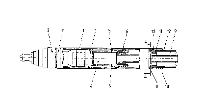
Fig. 1 shows a percussion boring machine having a transmitter
fitted at the rear end of the machine,
fig. 2 shows a cross-section through the housing on the line
II-II in Fig. 1, and~ Fig. 3 shows an axial longitudinal section on the line III-
III in Fig. 2.
DETAILED DESCRIPTION OF A PREFERRED EMBODIMENT OF THE INVENTION
In its design principle and method of operation the
percussion boring machine corresponds to the machine described
in German patent specification 21 57 295. It has a housing 1 with
an impact tip 2 and a striking piston 3. The striking piston 3
has in its rear part a compressed air chamber 4 with radial
control openings 5 and is guided to move longitudinally on a
control pipe 6 in the machine housing 1. It gives up its impact
energy when it meets the front end wall 7 of the machine housing
1. In the rear part of the machine housing there is a stop ring
8 through which the control pipe 6 projects and is connected to
a compressed air hose 9 on the far side of the stop ring.
Immediately behind the stop ring 8 there is a slot 10 in a sleeve
13 connected to the machine housing in the vicinity of which an
annular insert 11 is located. The slot 10 can be closed by means
of a cap or have a non-conductive mass which does not hinder the
transmitter signal cast into it. The insert 11 contains the
transmitter and is seated in the sleeve 13, which serves at the
same time as a connection for a follower pipe 12 which is pulled
by the percussion boring machine into the earth borehole which
the machine has created.
The annular insert 11 consists of an elastic and shock-
absorbent plastics material. It has a pocket 14 for a block 15,
preferably of a non-conductive elastic mass, for example
silicone. In this elastic mass a battery 16, a transmitter 17 and
a clinometer 18, for example a liquid sensor, are embedded side
by side and wired together in the usual manner.
As the machine advances the striking piston 3 moves back and
forth in the machine housing 1 under the influence of the
compressed air supplied to the striking piston chamber 4 through

CA 02223311 1997-12-02
the compressed air hose 9 and the control pipe 6, giving up its
impact energy substantially exclusively to the front en~ wall 7.
Only in the case of a reversal of the direction of movement,
which happens relatively rarely, is the striking piston 3
controlled so as to strike the stop ring 8 with its rear end.
Further details about this can be found in the German
specification 21 57 295. It follows from this that it is only
extremely rarely that the transmitter 17 with its sensitive
electronics and the clinometer 18 are subjected to the effect of
the ram blows of the striking piston 3. It is therefore subjected
to far less mechanical stress than a transmitter mounted in the
usual manner in the striking tip 2. In addition to this, as a
result of the particular way in which they are arranged the
transmitter 17, its battery and the clinometer 18 create
practically no requirement for additional space, for the
percussion boring machine in any case requires an annular
connection for the follower pipe 12 and as a result of the side-
by-side arrangement of battery, 1~, transmitter 17 and clinometer
18 the axial length of the insert 11 is only small.
Altogether, the greatest possible protection of the
sensitive transmitter and of the no less sensitive clinometer and
of the battery is thus produced with practically no need for
additional space. This is so even when - as in the case of very
long boreholes - a great deal of energy is needed so that several
batteries are required, as these can simply be disposed side-by-
side.

Dessin représentatif
Une figure unique qui représente un dessin illustrant l'invention.
États administratifs

2024-08-01 : Dans le cadre de la transition vers les Brevets de nouvelle génération (BNG), la base de données sur les brevets canadiens (BDBC) contient désormais un Historique d'événement plus détaillé, qui reproduit le Journal des événements de notre nouvelle solution interne.

Veuillez noter que les événements débutant par « Inactive : » se réfèrent à des événements qui ne sont plus utilisés dans notre nouvelle solution interne.

Pour une meilleure compréhension de l'état de la demande ou brevet qui figure sur cette page, la rubrique Mise en garde , et les descriptions de Brevet , Historique d'événement , Taxes périodiques et Historique des paiements devraient être consultées.

Historique d'événement

Description Date
Inactive : CIB expirée 2012-01-01
Inactive : CIB de MCD 2006-03-12
Demande non rétablie avant l'échéance 2000-12-04
Le délai pour l'annulation est expiré 2000-12-04
Réputée abandonnée - omission de répondre à un avis sur les taxes pour le maintien en état 1999-12-02
Demande publiée (accessible au public) 1998-06-04
Modification reçue - modification volontaire 1998-04-17
Inactive : Transfert individuel 1998-04-17
Inactive : CIB attribuée 1998-03-13
Symbole de classement modifié 1998-03-13
Inactive : CIB en 1re position 1998-03-13
Inactive : Lettre de courtoisie - Preuve 1998-03-03
Demande reçue - nationale ordinaire 1998-02-26
Inactive : Certificat de dépôt - Sans RE (Anglais) 1998-02-26
Inactive : Demandeur supprimé 1998-02-26

Historique d'abandonnement

Date d'abandonnement Raison Date de rétablissement
1999-12-02

Historique des taxes

Type de taxes Anniversaire Échéance Date payée
Taxe pour le dépôt - générale 1997-12-02
Enregistrement d'un document 1998-04-17
Titulaires au dossier

Les titulaires actuels et antérieures au dossier sont affichés en ordre alphabétique.

Titulaires actuels au dossier
TRACTO-TECHNIK PAUL SCHMIDT SPEZIALMASCHINEN
Titulaires antérieures au dossier
ALFONS HESSE
Les propriétaires antérieurs qui ne figurent pas dans la liste des « Propriétaires au dossier » apparaîtront dans d'autres documents au dossier.
Documents

Pour visionner les fichiers sélectionnés, entrer le code reCAPTCHA :


Pour visualiser une image, cliquer sur un lien dans la colonne description du document. Pour télécharger l'image (les images), cliquer l'une ou plusieurs cases à cocher dans la première colonne et ensuite cliquer sur le bouton "Télécharger sélection en format PDF (archive Zip)" ou le bouton "Télécharger sélection (en un fichier PDF fusionné)".

Liste des documents de brevet publiés et non publiés sur la BDBC .

Si vous avez des difficultés à accéder au contenu, veuillez communiquer avec le Centre de services à la clientèle au 1-866-997-1936, ou envoyer un courriel au Centre de service à la clientèle de l'OPIC.


Description du
Document 
Date
(aaaa-mm-jj) 
Nombre de pages   Taille de l'image (Ko) 
Dessin représentatif 1998-06-01 1 7
Description 1997-12-01 5 249
Abrégé 1997-12-01 1 16
Revendications 1997-12-01 2 46
Dessins 1997-12-01 3 56
Certificat de dépôt (anglais) 1998-02-25 1 165
Courtoisie - Certificat d'enregistrement (document(s) connexe(s)) 1998-07-21 1 140
Rappel de taxe de maintien due 1999-08-03 1 114
Courtoisie - Lettre d'abandon (taxe de maintien en état) 1999-12-29 1 185
Correspondance 1998-03-02 1 31