Sélection de la langue

Search

Sommaire du brevet 2224010 

Énoncé de désistement de responsabilité concernant l'information provenant de tiers

Une partie des informations de ce site Web a été fournie par des sources externes. Le gouvernement du Canada n'assume aucune responsabilité concernant la précision, l'actualité ou la fiabilité des informations fournies par les sources externes. Les utilisateurs qui désirent employer cette information devraient consulter directement la source des informations. Le contenu fourni par les sources externes n'est pas assujetti aux exigences sur les langues officielles, la protection des renseignements personnels et l'accessibilité.

Disponibilité de l'Abrégé et des Revendications

L'apparition de différences dans le texte et l'image des Revendications et de l'Abrégé dépend du moment auquel le document est publié. Les textes des Revendications et de l'Abrégé sont affichés :

  • lorsque la demande peut être examinée par le public;
  • lorsque le brevet est émis (délivrance).
(12) Brevet: (11) CA 2224010
(54) Titre français: DISPOSITIF ASSURANT L'ETANCHEITE ENTRE DES PARTIES MOBILES EN CONTACT MUTUEL
(54) Titre anglais: SEALING DEVICE BETWEEN MOVABLE PARTS IN MUTUAL CONTACT
Statut: Périmé et au-delà du délai pour l’annulation
Données bibliographiques
(51) Classification internationale des brevets (CIB):
  • F16J 15/08 (2006.01)
  • F16K 01/226 (2006.01)
(72) Inventeurs :
  • STARKE, WILFRIED (Allemagne)
(73) Titulaires :
  • MANNESMANN AKTIENGESELLSCHAFT
(71) Demandeurs :
  • MANNESMANN AKTIENGESELLSCHAFT (Allemagne)
(74) Agent: SMART & BIGGAR LP
(74) Co-agent:
(45) Délivré: 2007-05-15
(86) Date de dépôt PCT: 1996-06-06
(87) Mise à la disponibilité du public: 1996-12-27
Requête d'examen: 2003-04-16
Licence disponible: S.O.
Cédé au domaine public: S.O.
(25) Langue des documents déposés: Anglais

Traité de coopération en matière de brevets (PCT): Oui
(86) Numéro de la demande PCT: PCT/DE1996/001043
(87) Numéro de publication internationale PCT: DE1996001043
(85) Entrée nationale: 1997-12-08

(30) Données de priorité de la demande:
Numéro de la demande Pays / territoire Date
195 21 916.3 (Allemagne) 1995-06-09

Abrégés

Abrégé français

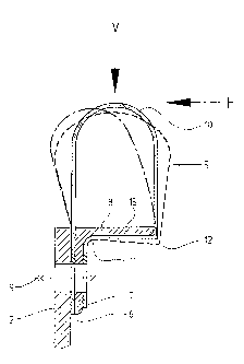
Le dispositif décrit assure l'étanchéité entre deux parties (1, 2) en contact mutuel, se déplaçant l'une par rapport à l'autre, notamment entre deux ailes de clapet ou entre une aile de clapet et une butée d'un accessoire pour conduite de gaz de fumée. Le dispositif comprend un élément élastique d'étanchéité (5) constitué d'une bande d'acier à ressort et pourvu de deux bords plats parallèles adjacents (6, 7) tournés du même côté et susceptibles d'être fixés d'un côté par un dispositif de serrage (9) sur une pièce de contact (1 ou 2), ainsi qu'une zone d'étanchéité (10) en arc. En dehors des bords de serrage, l'élément d'étanchéité (5) comprend une surface d'appui qui repose à plat sur la surface plate de support (15) d'un élément de support (8) qui peut lui aussi être assujetti par le dispositif de serrage (9) à une partie de contact (1 ou 2). L'autre partie de contact (2 ou 1) entre en contact avec l'élément d'étanchéité (5) au sommet de la zone d'étanchéité recourbée en arc (10) et les deux pièces de contact (1, 2) se déplacent l'une par rapport à l'autre à peu près tangentiellement à ce sommet. L'élément de support (8) se situe dans l'espace défini par l'élément courbe d'étanchéité (5).


Abrégé anglais


Device for sealing between two assembly parts (1, 2) movable relative to one
another,
especially between two damper blades or a damper blade and a stop of a flue
gas armature,
containing an elastic sealing element formed by a spring-steel strip (5),
which contains two
flat clamping edges (6, 7) arranged next to one another in a parallel fashion
and pointing
to the same side and securable by means of a clamping device (9) on one side
to one of the
assembly parts (1 or 2), as well as sealing zone (10) curved in an arc-shaped
manner,
whereby the sealing element (5) rests, with a resting surface located outside
of the clamping
edges (6, 7), flatly on the flat supporting surface (15) of a supporting
element (8), and the
supporting element (8) is also securable by means of the clamping device (9)
to one of the
assembly parts (1 or 2), and whereby the other assembly part (2 or 1) comes
into contact
with the sealing element (5) in the top area of the sealing zone (10) curved
in an arc-shaped
manner and the relative movement between the two assembly parts (1, 2) occurs
roughly
tangentially relative to this top area. According to the invention, the
supporting element
(8) is located inside of the space enclosed by the curved sealing element (5).

Revendications

Note : Les revendications sont présentées dans la langue officielle dans laquelle elles ont été soumises.


CLAIMS:
1. A device for providing a seal between two plant
components movable relative to one another, in particular
between two valve leaves or a valve leaf and a limit stop
for a flue gas fitting, comprising a resilient sealing
element which is formed of a spring steel strip and
comprises, together with an arcuately curved sealing zone,
two flat anchoring edges arranged in parallel next to each
other, directed towards the same side and attachable on one
side of the one plant component by means of a clamping
device, the sealing element resting flat on the flat bearing
surface of a supporting member via a supporting face located
externally of the anchoring edges and formed of at least one
bend between at least one of the anchoring edges and the
sealing zone and the supporting member likewise being
attachable to the one plant component by means of the
clamping device and the other plant component coming into
contact with the sealing element in the apex area of the
arcuately curved sealing zone and the relative movement
between the two plant components occurring approximately
tangentially to this apex area, wherein the supporting
member is arranged inside the space enclosed by the curved
sealing element.
2. A device according to claim 1, wherein two bends
are provided externally of the sealing zone in the
longitudinal direction of the sealing element and the inside
of the sealing element rests flat on the underside of the
supporting member in the area between the one bend and the
associated anchoring edge.
3. A device according to claim 2, wherein the two
bends are arranged on the same side of the sealing element
between the sealing zone and the corresponding anchoring

edge at a distance corresponding to the width of the bearing
surface of the supporting element.
4. A device according to claim 3, wherein the
supporting element takes the form of an L-shaped profile,
the inside of the first leg of the L-shaped profile forming
the bearing surface and the second leg of the L-shaped
profile anchoring the two anchoring edges to the plant
component by means of the clamping device.
5. A device according to claim 2, wherein the
supporting element takes the form of a flat retaining strip,
in that the two bends are arranged on opposing sides of the
sealing element relative to the sealing zone, and in that
the retaining strip anchors the two anchoring edges to the
plant component by means of the clamping device, the
supporting element extending as far as one bend.
6. A device according to any one of claims 1 to 5,
wherein the sealing element is secured to the rear of the
bearing surface of the supporting element over part of the
width of the bearing surface of the supporting member by
means of a backing member.
7. A device according to any one of claims 1 to 6,
wherein the sealing element is composed of mutually abutting
sections and each abutment joint area is overlapped by a
plug-in sleeve consisting of a spring steel strip.
11

Description

Note : Les descriptions sont présentées dans la langue officielle dans laquelle elles ont été soumises.


CA 02224010 2006-09-27
29882-7
Sealing Device Between Movable Parts in Mutual Contact
Description
The invention relates to a device for sealing between two assembly parts that
are movable
relative to one another.
From Dr, 38 15 402 Al, a device for sealing the contact zone between a movable
shut-off
eleinent of a pipeline and a stationary seat is known, which uses an elastic
seal in the form
of an elongated spring-steel strip in the sealing area. Outside of the arched
sealing zone,
in the longitudinal direction of the sealing element, the spring-steel strip
has two bends.
The two longitudinal edge areas of the spring-steel strip point to the same
side and are
placed one atop the other, as clamping edges, and can be attached on one side
to the
movable shut-off element or to the stationary seal seat by means of a clamping
device (e.g.,
a screw connection). This seal has proved to be very effective, particularly
when the
relative movement which occurs between the spring-steel strip and the matching
seal seat
during the closing process is roughly vertical relative to the arched sealing
zone. In cases
when the relative movement during closing is more tangential relative to the
arched sealing
zone, situations of extreme stress for the spring-steel seal sometimes
develop, which can
result in the spring-steel strip being lifted up from the supporting surface
and, in
consequence, in breakage of the spring-steel strip.
In order to avoid negative consequences of this type, it is known from WO
95/02136 to
provide a supporting profile in the interior of the sealing element. This
supporting profile,
1

CA 02224010 2006-09-27
29882-7
which serves as a hold-down device, rests on the supporting
surface of the spring-steel strip near the bend farthest
from the clamping point and prevents the strip from lifting
up. The hold-down device can be designed, for example, as a
roughly V-shaped profile, and it is secured between the
clamping edges of the spring-steel strip by means of the
clamping device. Because extraordinarily corrosive
conditions frequently occur in flue gas fittings, the hold-
down device, like the spring-steel strip, must be made of
high-alloy material, making it quite expensive. It is also
disadvantageous that when a large-area flue gas damper
equipped with one of the known sealing elements is opened,
the break-away torque resulting from the hold-down device
can be undesirably high.
The object of the invention is to further develop
a generic device in such a way that it is possible, upon
reaching the closed position, to reliably avoid the
impermissible lifting and deformation of the spring-steel
strip by tangential side-forces, at the lowest possible
material and assembly expense, without impermissibly
detracting from the required elastic deformability of the
sealing element; rather, the seal is to be more flexible,
i.e., softer, in nature, in order to achieve a reduction in
the break-away torque.
In accordance with the present invention, there is
provided a device for providing a seal between two plant
components movable relative to one another, in particular
between two valve leaves or a valve leaf and a limit stop
for a flue gas fitting, comprising a resilient sealing
element which is formed of a spring steel strip and
comprises, together with an arcuately curved sealing zone,
two flat anchoring edges arranged in parallel next to each
other, directed towards the same side and attachable on one
2

CA 02224010 2006-09-27
29882-7
side of the one plant component by means of a clamping
device, the sealing element resting flat on the flat bearing
surface of a supporting member via a supporting face located
externally of the anchoring edges and formed of at least one
bend between at least one of the anchoring edges and the
sealing zone and the supporting member likewise being
attachable to the one plant component by means of the
clamping device and the other plant component coming into
contact with the sealing element in the apex area of the
arcuately curved sealing zone and the relative movement
between the two plant components occurring approximately
tangentially to this apex area, wherein the supporting
member is arranged inside the space enclosed by the curved
sealing element.
The invention is explained in greater detail in
reference to the drawings. The drawings show:
Fig. 1 A cross-section through a sealing device
according to the invention with an L-profile as a supporting
element and indicated deformation lines;
Fig. 2 A cross-section through a sealing device
as in Fig. 1 with an additional washer element;
Fig. 3 A cross-section through a device according
to the invention with a holding strip as a supporting
element;
Fig. 4 A known sealing arrangement.
2a

CA 02224010 1997-12-08
70 520
A sealing arrangement according to the prior art as in WO 95/02136 is shown in
Fig. 4.
The two assembly parts that move relative to one another and must be sealed
off from one
another are identified by reference numbers 1 and 2. These assembly parts may
be, for
example, a shut-off damper 1, which is swung into its sealing position in a
fashion roughly
tangential relative to the stationary assembly part 2 with the spring-steel
strip 5, which is
indicated by the solid upper curved arrow. Of course, the spring-steel strip 5
could also
be attached to the moved assembly part in an alternate manner. This is
indicated by the
lower curved arrow in dashed lines. Naturally, it is also possible to equip
both of the
movable assembly parts with suitable spring-steel strips 5. Furthermore, it is
often the case,
as with multileaf dampers, that two immediately adjacent damper blades are
brought into
the closed position, i.e., that both assembly parts 1, 2 are moved at the same
time. In such
a case, in addition to the normal forces (sealing force), significant
tangential side-forces also
occur.
The spring-steel strip 5 has a sealing zone 10 curved in an arc-shaped
fashion. The two
longitudinal edges of this spring-steel strip 5 point to the same side and lie
atop one another
in parallel fashion as the clamping edges 6, 7. Between the clamping edge 7
and the sealing
zone 10, two bends 11, 12 of 90 each are formed in the spring-steel strip 5,
parallel to its
longitudinal edges. As a result, a supporting surface is formed on the spring-
steel strip 5;
this supporting surface rests flatly on a corresponding supporting surface 15
of a supporting
element 8, which has an L-profile in cross-section, and supports the spring-
steel strip 5 in
the closed position against the sealing force. The vertical leg of this L-
profile presses the
two clamping edges 6, 7 against the assembly part 2 by means of a clamping
device 9 (e.g.,
a screw connection) and thus fixes the spring-steel strip 5 in place on one
side on the
assembly part 2. In order to prevent the spring-steel strip 5 from lifting up
from the
supporting surface 15 in the area of the bend 12 when the assembly part 1
swings into the
closed position, a V-shaped profile 4 is provided as a hold-down device,
[which] presses on
the supporting surface in the interior of the arched spring-steel strip 5 in
the area of the
bend 12. The V-profile 4 is fixed in place between the clamping edges 6, 7 by
means of the
clamping connection 9. Figure 8 shows the spring-steel strip 5 in the non-
deformed state.
3

CA 02224010 1997-12-08
70 520
In contrast to the generic prior art, in which the supporting element 8, seen
in the
direction of the sealing force, is located underneath the sealing element 5,
i.e., outside of
the constructive area enclosed by the sealing element 5, in the embodiment
according to
the invention this supporting element 8 is arranged inside the constructive
area enclosed
by the sealing element 5. This is illustrated in Figures 1 to 3, which will be
described in
greater detail below. The same reference numbers as those used in Fig. 4 will
be used for
parts with the same functions.
The sealing device shown in cross-section in Fig. 1, which is clamped by means
of a screw
connection 9 onto the moving or non-moving assembly part 2 on one side, has an
L-profile
as the supporting element 8. The vertical leg of the L-profile is securely
connected to the
assembly part 2 by the screw connection 9. The sealing element formed by the
spring-steel
strip 5 lies with its arched sealing area 10 over the other (horizontal) leg
of the supporting
element 8. While the spring-steel strip 5 is executed in a completely smooth
manner
between the sealing zone 10 and the left clamping edge 6, it has two bends 11,
12,
preferably of 90 each, in its right-hand portion between the sealing zone 10
and the
clamping edge 7. The distance between these two bends 11, 12 corresponds to
the width
of the supporting surface 15 on the lower side of the horizontal leg of the
supporting
element 8. In the non-stressed state, therefore, this portion (resting
surface) of the spring-
steel strip 5 located outside of the clamping edges 6, 7 rests completely
flatly on the
supporting surface 15. Figure 1 also shows, qualitatively, how the spring-
steel strip 5 is
deformed by a force component V (dashed line) acting vertically on the sealing
zone 10 or
by a force component H (dot-dashed line) oriented tangentially to the sealing
zone 10.
These two force components act when the sealing device is brought into its
closed position.
It can be seen that the spring-steel strip 5 cannot be lifted up by tangential
side-forces H
upon closing. If the tangential side-force H acts in the opposite direction,
as happens when
a shut-off damper is opened, the spring-steel strip 5 yields to the right, so
that the required
break-away torque is significantly reduced. After the shut-off damper has been
moved out
of the sealing seat, the spring-steel strip 5 springs back into its initial
position and rests on
the
4

CA 02224010 1997-12-08
70 520
supporting surface 15. Furthermore, the sealing device according to the
invention possesses
sufficient elasticity to absorb the vertically-acting sealing forces V. In
order to increase
rigidity against these sealing forces in special cases, it may be advantageous
to securely hold
the spring-steel strip 5 with its lower side on the supporting surface 15,
over a partial area
of the supporting surface 15, by means of a suitably shaped washer element 14
that can also
be secured by the screw connection 9. These washer elements 14 may be arranged
continuously or separated from one another and can be designed, for example,
as suitably
curved washer discs.
Figure 3 shows, in cross-section, a sealing device according to the invention
that functions
in principle in the same manner as that in Figure 2. The only difference is
that instead of
an L-profile, a simple flat (planar) holding strip is used as the supporting
element 8.
Mentally, Figure 3 is obtained from Figure 2 by swinging the vertically-drawn
profil leg
of the supporting element 8 by 90 clockwise into the plane of the other leg.
In this way,
bend 11 is eliminated, and a bend 13 is created between the clamping edge 6
and the sealing
zone 10. In terms of deformation, this embodiment behaves exactly like that in
Figure 2
or, when the washer element 14 is omitted, like that in Figure 1.
In cases when the areas to be sealed off have a very large longitudinal
extension, it is
advisable for the sealing device according to the invention to be composed of
partial pieces
of a standard length (e.g., 1 m). The individual partial pieces are placed so
as to abut one
another at their end faces. In order to ensure that in each case both of the
two abutting
ends behave in the same manner, it is advisable to provide one end of a
partial length, on
its inner side or outer side, with a narrow affixed spring-steel strip, so
that the
corresponding end of the next partial piece can be slipped in or on in an
exactly aligned
manner, in the sense of a sleeve connection. It is advantageous to limit the
length of this
additional spring-steel strip in such a manner that it runs outside of the
clamping points
and bends, i.e., essentially only in the area of the sealing zone 10 and the
two attached side
areas. Alternatively, an additional

CA 02224010 1997-12-08
70 520
spring-steel strip of this type could also be placed externally over the
abutment area and
secured accordingly.
6

Dessin représentatif
Une figure unique qui représente un dessin illustrant l'invention.
États administratifs

2024-08-01 : Dans le cadre de la transition vers les Brevets de nouvelle génération (BNG), la base de données sur les brevets canadiens (BDBC) contient désormais un Historique d'événement plus détaillé, qui reproduit le Journal des événements de notre nouvelle solution interne.

Veuillez noter que les événements débutant par « Inactive : » se réfèrent à des événements qui ne sont plus utilisés dans notre nouvelle solution interne.

Pour une meilleure compréhension de l'état de la demande ou brevet qui figure sur cette page, la rubrique Mise en garde , et les descriptions de Brevet , Historique d'événement , Taxes périodiques et Historique des paiements devraient être consultées.

Historique d'événement

Description Date
Le délai pour l'annulation est expiré 2015-06-08
Lettre envoyée 2014-06-06
Accordé par délivrance 2007-05-15
Inactive : Page couverture publiée 2007-05-14
Inactive : Taxe finale reçue 2007-03-05
Préoctroi 2007-03-05
Un avis d'acceptation est envoyé 2007-01-25
Lettre envoyée 2007-01-25
Un avis d'acceptation est envoyé 2007-01-25
Inactive : Approuvée aux fins d'acceptation (AFA) 2007-01-10
Modification reçue - modification volontaire 2006-09-27
Inactive : Dem. de l'examinateur par.30(2) Règles 2006-03-27
Inactive : CIB de MCD 2006-03-12
Lettre envoyée 2003-05-29
Exigences pour une requête d'examen - jugée conforme 2003-04-16
Toutes les exigences pour l'examen - jugée conforme 2003-04-16
Requête d'examen reçue 2003-04-16
Symbole de classement modifié 1998-03-30
Inactive : CIB en 1re position 1998-03-30
Inactive : CIB attribuée 1998-03-30
Symbole de classement modifié 1998-03-30
Lettre envoyée 1998-03-06
Inactive : Notice - Entrée phase nat. - Pas de RE 1998-03-06
Demande reçue - PCT 1998-03-04
Demande publiée (accessible au public) 1996-12-27

Historique d'abandonnement

Il n'y a pas d'historique d'abandonnement

Taxes périodiques

Le dernier paiement a été reçu le 2006-05-23

Avis : Si le paiement en totalité n'a pas été reçu au plus tard à la date indiquée, une taxe supplémentaire peut être imposée, soit une des taxes suivantes :

  • taxe de rétablissement ;
  • taxe pour paiement en souffrance ; ou
  • taxe additionnelle pour le renversement d'une péremption réputée.

Les taxes sur les brevets sont ajustées au 1er janvier de chaque année. Les montants ci-dessus sont les montants actuels s'ils sont reçus au plus tard le 31 décembre de l'année en cours.
Veuillez vous référer à la page web des taxes sur les brevets de l'OPIC pour voir tous les montants actuels des taxes.

Titulaires au dossier

Les titulaires actuels et antérieures au dossier sont affichés en ordre alphabétique.

Titulaires actuels au dossier
MANNESMANN AKTIENGESELLSCHAFT
Titulaires antérieures au dossier
WILFRIED STARKE
Les propriétaires antérieurs qui ne figurent pas dans la liste des « Propriétaires au dossier » apparaîtront dans d'autres documents au dossier.
Documents

Pour visionner les fichiers sélectionnés, entrer le code reCAPTCHA :


Pour visualiser une image, cliquer sur un lien dans la colonne description du document. Pour télécharger l'image (les images), cliquer l'une ou plusieurs cases à cocher dans la première colonne et ensuite cliquer sur le bouton "Télécharger sélection en format PDF (archive Zip)" ou le bouton "Télécharger sélection (en un fichier PDF fusionné)".

Liste des documents de brevet publiés et non publiés sur la BDBC .

Si vous avez des difficultés à accéder au contenu, veuillez communiquer avec le Centre de services à la clientèle au 1-866-997-1936, ou envoyer un courriel au Centre de service à la clientèle de l'OPIC.


Description du
Document 
Date
(aaaa-mm-jj) 
Nombre de pages   Taille de l'image (Ko) 
Dessin représentatif 1998-04-01 1 5
Description 1997-12-07 6 244
Abrégé 1997-12-07 1 29
Revendications 1997-12-07 3 81
Dessins 1997-12-07 4 45
Description 2006-09-26 7 280
Revendications 2006-09-26 2 79
Dessin représentatif 2007-04-25 1 6
Rappel de taxe de maintien due 1998-03-04 1 111
Avis d'entree dans la phase nationale 1998-03-05 1 193
Courtoisie - Certificat d'enregistrement (document(s) connexe(s)) 1998-03-05 1 118
Rappel - requête d'examen 2003-02-09 1 112
Accusé de réception de la requête d'examen 2003-05-28 1 174
Avis du commissaire - Demande jugée acceptable 2007-01-24 1 161
Avis concernant la taxe de maintien 2014-07-17 1 172
PCT 1998-02-23 5 144
PCT 1997-12-07 13 452
Taxes 2000-06-04 1 38
Correspondance 2007-03-04 1 38
Taxes 2007-05-30 1 27
Taxes 2009-06-07 1 28